This chapter describes the different topologies for out-of-band deployment of DANZ Monitoring Fabric.
DANZ Monitoring Fabric Topologies
DANZ Monitoring Fabric (DMF) supports the implementation of out-of-band monitoring using a single switch or with many switches for a scalable, high-availability topology. This topology supports thousands of filter and delivery ports.
This section provides a summary of the recommended deployments.
Single Switch Topology
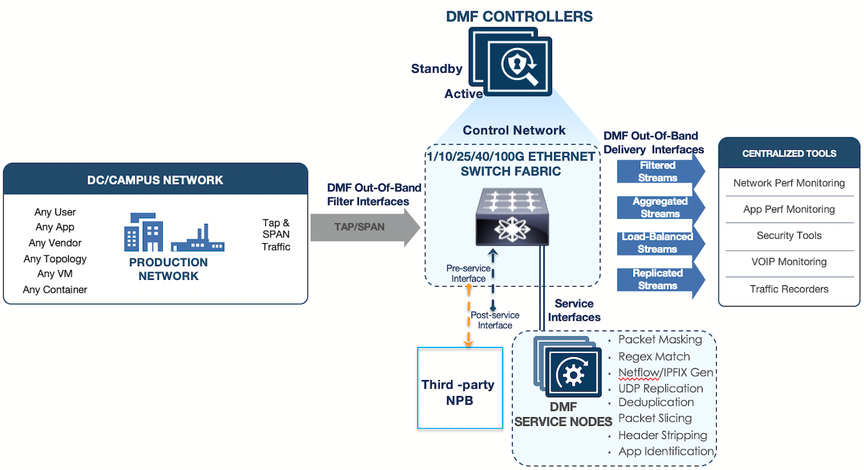
The single switch topology is the most basic design for small-scale environments, where a single switch provides enough filter interfaces, delivery interfaces, and optional service interfaces for connecting to NPBs for various packet manipulation operations, such as time stamping and packet slicing.
Figure 1. DANZ Monitoring Fabric (DMF) Single Switch Topology
This design option is most useful in the following scenarios:
The environment does not need to scale beyond the interfaces provided by a single DMF Out-of-Band (OOB) switch.
A single switch topology improves cable management when filter and delivery ports are physically dispersed throughout the data center.
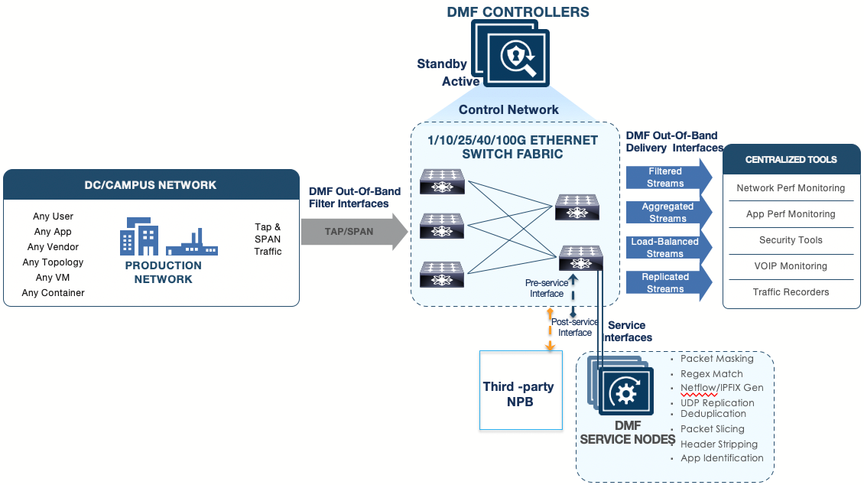
Two-Tier Topology
A two-tier design, shown in the figure below, is most useful in the following scenarios:
Medium-to-high port scalability requirements.
Production network TAPs are dispersed across the data center and require aggregation.
Tools are physically consolidated, and the traffic needs to be aggregated.
When deploying this topology, ensure the following requirements:
Only use core links between monitoring switches in different tiers. Depending on port availability and the bandwidth requirements, the core links can be 10, 25, 40, or 100 GbE.
Avoid connecting links between filter switches to help ensure efficient path computation.
Connect at least two links between tiers for link redundancy. The total number of physical links between the tiers will vary according to the amount of oversubscription in the design.
Service nodes should be connected to the delivery switch to send the aggregated traffic to the service nodes (NPBs).
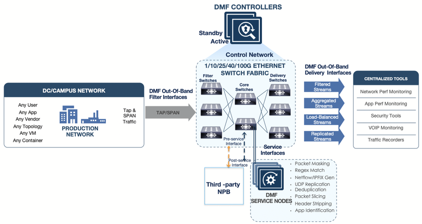
Three-Tier Any-Tap-to-Any-Tool Topology
A three-tier design, as shown in the figure below, is most useful in the following scenarios:
Large-scale deployments where hundreds of TAP ports are installed across the data center.
Traffic from TAPs must be aggregated, and the aggregated traffic forwarded to analysis tools in different locations. This design provides any-TAP-to-any-tool connectivity.
With this topology, ensure the following requirements are satisfied:
40 or 100 GbE links are recommended to the core switches.
Connect each filter switch to at least two core tier switches for redundancy. Depending on the amount of oversubscription in the design and on port availability, more ports can be connected between tiers.
Service nodes should be connected to a core (aggregation) switch so that aggregated traffic can be delivered to the service nodes (NPBs).
Avoid connecting links between filter switches to help ensure efficient path computation.