Installing and Configuring the DMF Controller
This chapter describes the basic procedure for installing the DANZ Monitoring Fabric (DMF) Controller software.
Connecting to the Controller
The DANZ Monitoring Fabric (DMF) Controller can be deployed as a hardware appliance, a one-RU hardware device containing preloaded software, or as a Virtual Machine (VM).
- Attach a monitor and a keyboard directly to the appliance's VGA and USB ports.
- Use a terminal server to connect to the appliance console port and telnet to the terminal server.
- When deploying the Controller as a VM, connect to the VM console.
Connecting to the Controller Appliance Using a Terminal Server
To connect the serial connection on a Controller appliance to a terminal server, complete the following steps:
- Obtain a serial console cable with a DB-9 connector on one end and an RJ-45 connector on the other.
- Connect the DB-9 connector to the hardware appliance DB-9 port (not the VGA port) and the RJ45 to the terminal server.
- Configure the terminal server port baud rate to 115200.
- Set the port baud rate of 115200 on the terminal server.
- On some terminal servers, the saved configuration must be reloaded after changing the baud rate.
- You should now be able to use Telnet or SSH to access the hardware appliance serial console through the terminal server.
Configuring the Active Controller Using the First Boot Script
- IP address for the active and standby Controller
- The subnet mask and the default gateway IP address
- NTP server IP address
- Host name
- (Optional) DNS server IP address
- (Optional) DNS search domain name
Configuring the Standby Controller
Joining Standby Controller to Existing Cluster
Powering on the hardware appliance or the VM with the pre-installed DMF software prompts the user to log in as admin for the first-time configuration.
Moving existing Standby Controller to different IPv4 subnet
Moving an Existing Standby Controller to a Different Controller Cluster
Follow the procedure below to move an existing standby Controller to a different Controller cluster.
Accessing the DANZ Monitoring Fabric Controller
This section describes connecting to the DANZ Monitoring Fabric (DMF) Controller.
To access the active DMF Controller, use the IP address of the active Controller. If configured, use the cluster's Virtual IP (VIP) as described in the Configuring the Cluster Virtual IP section.
Refer to the Using Local Groups and Users to Manage DMF Controller Access section to manage administrative user accounts and passwords.
Using the DANZ Monitoring Fabric CLI
Once the DANZ Monitoring Fabric (DMF) Controllers are up and running, log in to the DMF Controller using the VM local console or SSH.
- login mode: Commands available immediately after logging in, with the broadest possible context.
- enable mode: Commands that are available only after entering the enable command.
- config mode: Commands that significantly affect system configuration and are used after entering the configured command. Access sub-modes from this mode.
Enter sub-modes from config mode to provision specific monitoring fabric objects. For example, the switch command changes the CLI prompt to (config-switch)# to configure the switch identified by the switch DPID or alias.
After logging in, the CLI appears in the login mode where the default prompt is the system name followed by a greater than sign (>), as in the following example.
controller-1>
(#), as shown below.
controller-1> enable
controller-1#
(config)#, as shown below.
controller-1> enable
controller-1# configure
controller-1(config)#
controller-1(config)# switch filter-1
controller-1(config-switch)#
controller-1(config)# end
controller1#
To view a list of the commands available from the current mode or submode, enter the help command. To view detailed online help for the command, enter the help command followed by the command name.
To display the options available for a command or keyword, enter the command or keyword followed by a question mark (?).
Capturing CLI Command Output
controller-1> show running-config | grep <service unmanaged-service TSTS>
post-service pst2
pre-service pst
copy running-config scp://<username@scp_server>//<file>
Using the DANZ Monitoring Fabric GUI
- Firefox
- Chrome
- Microsoft Edge
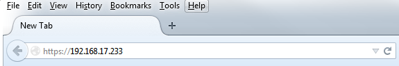
To connect to the DMF GUI, use the IP address assigned to the DMF Controller. The following figure shows a browser connecting to the GUI using HTTPS at the IP address 192.168.17.233.
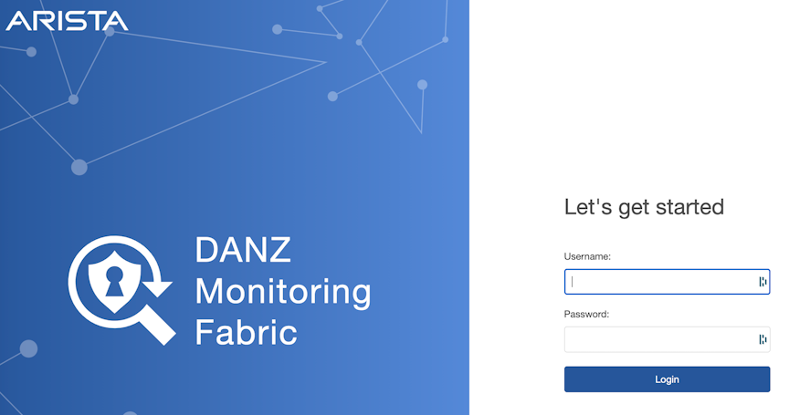
Use the admin username and password configured for DMF during installation or any user account and password configured with administrator privileges. A user in the read-only group will have access to options for monitoring fabric configuration and activity but cannot change the configuration.

- Fabric: manage DMF switches and interfaces.
- Monitoring: manage DMF policies, services, and interfaces.
- Maintenance: configure fabric-wide settings (clock, SNMP, AAA, sFlow®*, Logging, Analytics Configuration).
- Integration: manage the integration of vCenter instances to allow monitoring traffic using DMF.
- Security: manage administrative access.
- A profile page that displays or edits user preferences, the ability to change the password or sign out.
The newly designed dashboard displays information about the Controller, including switches, interfaces, policies, and Smart Nodes.
Managing the DMF Controller Cluster
This section describes configuring settings for a DANZ Monitoring Fabric (DMF) cluster or both active and standby Controllers. Most configuration occurs on the active Controller, which synchronizes the standby Controller.
Verifying Cluster Configuration
- Both active and standby must be in the same IP subnet.
- Firewall configurations are separate for active and standby, so manually keep the configuration consistent between the two nodes.
- NTP service is required to establish a cluster. Starting with DMF 7.0.0, the active Controller provides the NTP service for the cluster and connected switches. The Controller should sync the time from an external NTP server for this service to work.
- When SNMP service is enabled, it must be manually configured to be consistent on both nodes. To verify the cluster state, use the following commands:
- Enter the show controller details command from either the active or standby Controller.
controller-1(config)# show controller details
Cluster Name : dmf-cluster
Cluster UID : 8ef968f80bd72d20d30df3bc4cb6b271a44de970
Cluster Virtual IP : 10.106.8.4
Redundancy Status : redundant
Redundancy Description : Cluster is Redundant
Last Role Change Time : 2020-11-19 18:12:49.699000 UTC
Cluster Uptime : 3 weeks, 1 day
# IP          @  Node Id  Domain Id  State    Status     Uptime
- |---------- |- |------- |--------- |------- |--------- |-------------------- |
1 10.106.8.3     5784     1          standby  connected  11 hours, 6 minutes
2 10.106.8.2  *  25377    1          active   connected  11 hours, 11 minutes
~~~~~~~~~~~~~~~~~~~~~~~~~~~~~~~~~~~~~~~~~~~~~~~~~~~~~~~ Failover History ~~~~~~~~~~~~~~~~~~~~~~~~~~~~~~~~~~~~~~~~~~~~~~~~~~~~~~~
# New Active  Time completed                  Node   Reason                 Description
- |---------- |------------------------------ |----- |--------------------- |------------------------------------------------------- |
1 25377       2020-11-19 18:12:38.299000 UTC  25377  cluster-config-change  Changed connection state: cluster configuration changed
controller-1(config)#
- Enter the show controller command to display the current Controller roles from either the active or standby node, as in the following example.
controller-1(config)# show controller
Cluster Name : dmf-cluster
Cluster Virtual IP : 10.106.8.4
Redundancy Status : redundant
Last Role Change Time : 2020-11-19 18:12:49.699000 UTC
Failover Reason : Changed connection state: cluster configuration changed
Cluster Uptime : 3 weeks, 1 day
# IP          @  State    Uptime
- |---------- |- |------- |-------------------- |
1 10.106.8.3     standby  11 hours, 24 minutes
2 10.106.8.2  *  active   11 hours, 29 minutes
controller-1(config)#
Configuring the Cluster Virtual IP
controller-1> enable
controller-1# config
controller-1(config)# controller
controller-1(config-controller)# virtual-ip 10.106.8.4
controller-1(config-controller)#
Verify the VIP by entering the show controller command.
controller-1(config)# show controller
Cluster Name : dmf-cluster
Cluster Virtual IP : 10.106.8.4
Redundancy Status : redundant
Last Role Change Time : 2020-11-19 18:12:49.699000 UTC
Failover Reason : Changed connection state: cluster configuration changed
Cluster Uptime : 3 weeks, 1 day
# IP          @  State    Uptime
- |---------- |- |------- |-------------------- |
1 10.106.8.3     standby  11 hours, 24 minutes
2 10.106.8.2  *  active   11 hourmvs, 29 minutes
controller-1(config)#
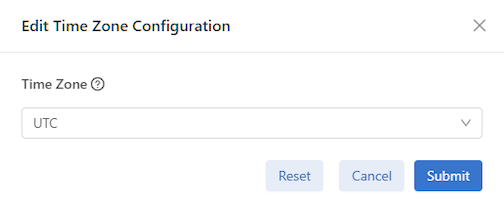
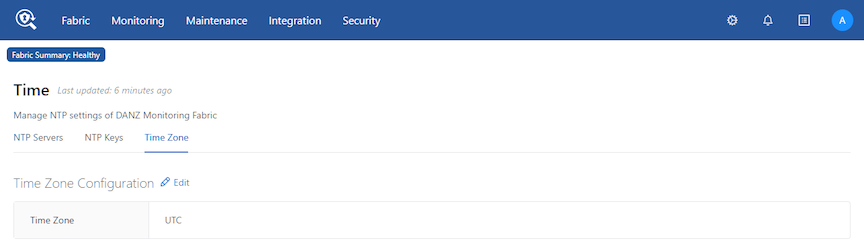
Setting the Time Zone
To view or change the current time zone on the DMF Controller, complete the following steps.
GUI Procedure
from the main menu.
The dashboard displays the last updated time on the system, information about the configured NTP server, and provides an option for refreshing the NTP synchronization with the NTP server running on the DMF Master Controller.
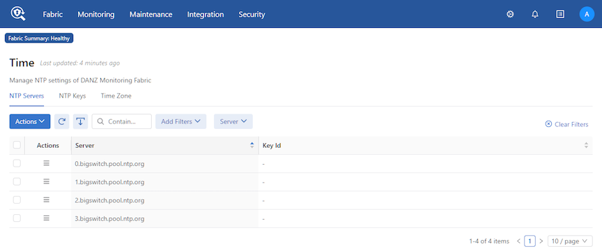
- NTP Servers
- NTP Keys
- Time Zone
CLI Procedure
[no] ntp time-zone <time-zone>
Replace time-zone with the specific string for the desired time zone. To see a list of supported values, press Tab after the clock set command. Certain values, such as America/, are followed by a slash (/). These values must be followed by a keyword for the specific time zone. View the supported time zones by pressing Tab again after selecting the first keyword.
controller-1( (config)# ntp time-zone America/Los_Angeles
Warning: Active REST API sessions will not be informed of updates to time-zone.
Warning: Please logout and login to any other active CLI sessions to
Warning: update the time-zone for those sessions.
controller-1( (config)#
controller-1(config-controller)# no ntp time-zone
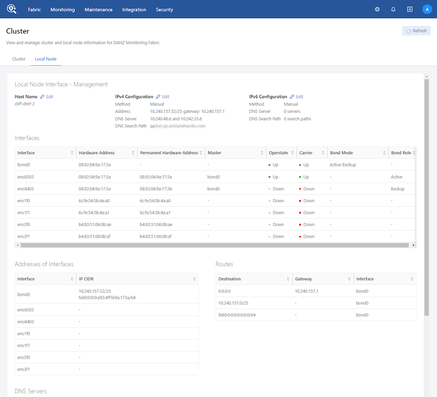
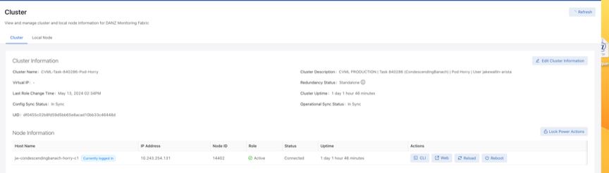
Viewing Controller and Cluster Status
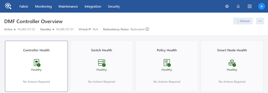
This page also provides configuration options that let you view and change fabric-wide settings.
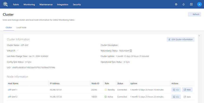
- Cluster
- Cluster Information
- Node Information
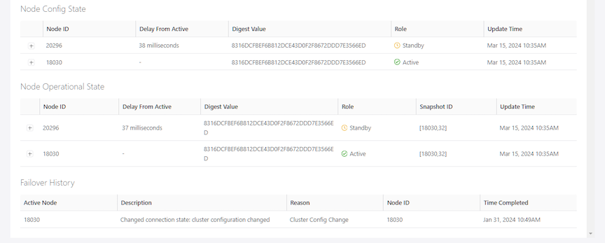
- Node Config State
- Node Operational State
- Failover History
- Local Node
- Local Node Interface - Management
- Interfaces
- Addresses of Interfaces
- DNS Servers
CLI Procedure
controller-1(config)# show controller details
Cluster Name : dmf-cluster
Cluster UID : 8ef968f80bd72d20d30df3bc4cb6b271a44de970
Cluster Virtual IP : 10.106.8.4
Redundancy Status : redundant
Redundancy Description : Cluster is Redundant
Last Role Change Time : 2020-11-19 18:12:49.699000 UTC
Cluster Uptime : 3 weeks, 1 day
# IP          @  Node Id  Domain Id  State    Status     Uptime
- |---------- |- |------- |--------- |------- |--------- |-------------------- |
1 10.106.8.3     5784     1          standby  connected  11 hours, 6 minutes
2 10.106.8.2  *  25377    1          active   connected  11 hours, 11 minutes
~~~~~~~~~~~~~~~~~~~~~~~~~~~~~~~~~~~~~~~~~~~~~~~~~~~~~~~ Failover History ~~~~~~~~~~~~~~~~~~~~~~~~~~~~~~~~~
# New Active  Time completed                  Node   Reason                 Description
- |---------- |------------------------------ |----- |--------------------- |---------------------------- |
1 25377       2020-11-19 18:12:38.299000 UTC  25377   cluster-config-change  Changed connection state:
cluster configuration changed
controller-1(config)#
- access-control: Configure access control of the Controller
- cluster-name: Configure cluster name
- description: Configure cluster description
- virtual-ip: Configure management virtual IP
- hostname: Configure hostname for this host
- interface: Configure controller network interface
- snmp-server: Configure local SNMP attributes
Saving and Restoring Controller Configuration
A properly configured Controller requires no regular maintenance. However, Arista Networks recommends periodically saving a copy of the Controller running-config to a location outside the Controller. Use the copy command from the Controller to an FTP server.
# copy running-config scp://admin:admin@myserver/configs
The format for the remote server username, password, and path name is as follows: scp://<user>:<password>@<host>/<path_to_saved_config>
CLI Procedure
Reloading and Rebooting a Controller Using the DMF UI
To use the Reload or Reboot functions, navigate to the DANZ Monitoring Fabric (DMF) Maintenance -> Cluster page. Reload and Reboot appear under the Actions column in the Node Information table.
To use the Reload and Reboot features, a logged-in DMF user requires read/write sysops permissions on the active cluster node.
For an active/standby cluster configuration, the user can reload or reboot the node.
When the active node is reloaded or rebooted, the standby node becomes the new active node. When the user logs in to the Virtual IP (VIP) address of an active/standby cluster configuration, the user can reload or reboot the active node. The VIP logs in to the new active node without the user changing IP addresses.
The new standby node will not have the Reload or Reboot functionality unless the user directly logs in to that node.
Workflow
The following information describes the expected behavior of the Reload and Reboot functions based on the type of configuration:
| Action | Single Node |
|---|---|
| Reload | Click the submit button -> Display submit button loading -> Redirects to login page. |
| Reboot | Click the submit button -> Display submit button loading -> Redirects to the login page. |
| Action | Two Node Cluster without Virtual IP (VIP) | |
|---|---|---|
| Log into Active | Log into Standby | |
| Reload |
Click the submit button -> Display submit button loading -> Redirect to the login page (it doesn’t redirect because the session is still active). This node now becomes the standby node). |
Click the submit button -> Display submit button loading -> Redirect to the login page (it doesn’t redirect because the session is still active. This node will remain the standby node). |
| Reboot |
Same as above. |
Same as above. |
| Action | Two Node Cluster with Virtual IP (VIP) | ||
|---|---|---|---|
| Log into VIP | Log into Active | Log into Standby | |
| Reload |
Click the submit button -> Display submit button loading -> Redirect to the login page. The active and standby nodes are swapped. The VIP has access to the new active node. |
Same behavior as active node without VIP. | Same behavior as the standby node without VIP. |
| Reboot | Same as above. | Same behavior as active node without VIP. | Same behavior as the standby node without VIP. |
UI Notifications
The standby banner in the UI displays a link to the active node. This link appears when a user is logged in to the standby node.
Limitations
- Executing the power action on a node is only possible if the user logs in to that node. For example, if the user logs in to the active node, they will only be able to execute power actions on the active node; they will have to log in to the standby node to execute power actions on the standby node.
- The CLI supports a third power action: shutdown. The UI does not include shutdown support because of the previous limitation. When executing a shutdown on the currently logged-in node, the user loses connection with the UI and cannot view the updated status of the node.
- The CLI supports the reload and reboot functionalities for both the active and the standby nodes.
Copying Files Between a Workstation and a DMF Controller
- Certificate (//cert)
- Private key (//private-key/<name>)
- Running configuration (//running-config)
- Snapshots (//snapshot)
- Controller image files (//image)
Copying into //snapshot on the controller overwrites the current running-config except the local node configuration
Copying into //running-config merges the destination configuration to the running-config on the controller
scp <filename> admin@<controller-ip>://<keyword>
scp DMF-8.0.0-Controller-Appliance-2020-12-21.iso This email address is being protected from spambots. You need JavaScript enabled to view it.://image
This example copies the DMF 8.0.0 ISO file from the local workstation or server to the image partition of the DMF Controller running at 10.2.1.183.
c:\>pscp -P 22 -scp DMF-8.0.0-Controller-Appliance-2020-12-21.iso This email address is being protected from spambots. You need JavaScript enabled to view it.://image
admin-upgrade, which should be a member of the admin group. Use the PSCP command on a Windows workstation to copy the file to the Controller.
c:\>pscp -P 22 -scp <filename> admin@<controller-ip>://<keyword>
SCP command to get the following files from the Controller and copy them to the local file system of the server or workstation.
- Running configuration (
copy running-config <dest>) - Snapshots (
copy snapshot:// <dest>)
controller-1# copy snapshot:// scp://This email address is being protected from spambots. You need JavaScript enabled to view it.://anet/DMF-720.snp controller-1# copy running-config scp://This email address is being protected from spambots. You need JavaScript enabled to view it.://anet/DMF-720.cfg
Merge and Replace Parameters of Copy Config
When copying a text-based configuration file with the copy <text config> running-config command, it is possible to specify either of two parameters: merge or replace.
Replace:
The replace option applies a text-based configuration as a full override of the existing one. In other words, it erases the old configuration and applies the new one to a blank slate.
For example, if current_policy.txt is the current running-config on the Controller and policy_modified.txt is a configuration file with modified NTP time zone, NTP servers, recorder-node name, and other policy changes, it is possible first to verify the differences and then to replace the current configuration with a modified configuration file by using the following commands:
dmf-controller-1# compare file://current_policy.txt file://policy_modified.txt
3c3
< ! Current Time: 2024-06-03 22:48:14 UTC
---
> ! Current Time: 2024-06-03 22:44:04 UTC
8,12c8,10
< ntp time-zone America/Los_Angeles
< ntp server ntp1.aristanetworks.com
< ntp server ntp2.aristanetworks.com
< ntp server ntp3.aristanetworks.com
< ntp server ntp4.aristanetworks.com
---
> ntp time-zone UTC
> ntp server time.google.com
> ntp server time.windows.com
79c77
< recorder-node device rn1
---
> recorder-node device rn-modified
103c101
<   description testone
---
>   description testone-modified
134,135c132,133
<   delivery-interface leaf-1-eth3
<   filter-interface ixia-5-6
---
>   delivery-interface leaf-1-eth3-modified
>   filter-interface ixia-5-6-modified

dmf-controller-1# copy file://policy_modified.txt running-config replace
Applied Command: 4: ntp time-zone UTC:
Warning: Active REST API sessions will not be informed of updates to time-zone.
Applied Command: 4: ntp time-zone UTC:
Warning: Please logout and login to any other active CLI sessions to
Applied Command: 4: ntp time-zone UTC:
Warning: update the time-zone for those sessions.
Lines applied: 142, No Errors, Warnings: 3; Commit completed

dmf-controller-1# show run ntp

! ntp
ntp server time.google.com
ntp server time.windows.com

dmf-controller-1# show run ntp details

! ntp
ntp time-zone UTC
ntp server time.google.com
ntp server time.windows.com

dmf-controller-1# show run recorder-node

! recorder-node
recorder-node device rn-modified
  mac 52:54:00:59:57:b0

dmf-controller-1# show run policy | grep modified
  description testone-modified
  delivery-interface leaf-1-eth3-modified
  filter-interface ixia-5-6-modified
Merge:
The merge option applies a text-based configuration additively to an existing one. In other words, it adds a new configuration delta to the current configuration. In the case of the previous example, using the merge option would have failed because it would have added a conflicting Recorder Node with a duplicate MAC address, as shown below:
dmf-controller-1# copy file://policy_modified.txt running-config merge
Applied Command: 4: ntp time-zone UTC:
Warning: Active REST API sessions will not be informed of updates to time-zone.
Applied Command: 4: ntp time-zone UTC:
Warning: Please logout and login to any other active CLI sessions to
Applied Command: 4: ntp time-zone UTC:
Warning: update the time-zone for those sessions.
Error: Validation failed: Multiple devices (switch/service) specify 52:54:00:59:57:b0 as mac address
Lines applied: 142, No Errors, Warnings: 0; Commit: failed, changes rolled back

dmf-controller-1# show run recorder-node

! recorder-node
recorder-node device rn1
  mac 52:54:00:59:57:b0
If you wanted to apply just a one-line configuration change (let's say, change only the NTP time zone), the one-line change would work with the merge option but not with the replace option, since replace requires a full valid configuration to be applied, as shown below:
dmf-controller-1# show run ntp details

! ntp
ntp time-zone UTC
ntp server ntp1.aristanetworks.com
ntp server ntp2.aristanetworks.com
ntp server ntp3.aristanetworks.com
ntp server ntp4.aristanetworks.com

dmf-controller-1# show file test.txt
ntp time-zone America/Los_Angeles

dmf-controller-1# copy file://test.txt running-config replace
300.0% |****************************************************************************************************************************************************************************************************************************************************************************************************************************************************************************************************************************************************************************************************************************************************************************************************************************************************Applied Command: 3: ntp time-zone America/Los_Angeles:
300.0% |****************************************************************************************************************************************************************************************************************************************************************************************************************************************************************************************************************************************************************************************************************************************************************************************************************************************************Warning: Active REST API sessions will not be informed of updates to time-zone.
300.0% |****************************************************************************************************************************************************************************************************************************************************************************************************************************************************************************************************************************************************************************************************************************************************************************************************************************************************Applied Command: 3: ntp time-zone America/Los_Angeles:
300.0% |****************************************************************************************************************************************************************************************************************************************************************************************************************************************************************************************************************************************************************************************************************************************************************************************************************************************************Warning: Please logout and login to any other active CLI sessions to
300.0% |****************************************************************************************************************************************************************************************************************************************************************************************************************************************************************************************************************************************************************************************************************************************************************************************************************************************************Applied Command: 3: ntp time-zone America/Los_Angeles:
300.0% |****************************************************************************************************************************************************************************************************************************************************************************************************************************************************************************************************************************************************************************************************************************************************************************************************************************************************Warning: update the time-zone for those sessions.
400.0% |**********************************************************************************************************************************************************************************************************************************************************************************************************************************************************************************************************************************************************************************************************************************************************************************************************************************************************************************************************************************************************************************************************************************************************************************************************************************************************************************Error: Validation failed: deletion of predefined admin group is not allowed.
Lines applied: 1, No Errors, Warnings: 0; Commit: failed, changes rolled back
Instead, using the (default) merge option to incrementally add a line would succeed, as shown below:
dmf-controller-1# show run ntp details

! ntp
ntp time-zone UTC
ntp server ntp1.aristanetworks.com
ntp server ntp2.aristanetworks.com
ntp server ntp3.aristanetworks.com
ntp server ntp4.aristanetworks.com

dmf-controller-1# show file test.txt
ntp time-zone America/Los_Angeles

dmf-controller-1# copy file://test.txt running-config
300.0% |****************************************************************************************************************************************************************************************************************************************************************************************************************************************************************************************************************************************************************************************************************************************************************************************************************************************************Applied Command: 3: ntp time-zone America/Los_Angeles:
300.0% |****************************************************************************************************************************************************************************************************************************************************************************************************************************************************************************************************************************************************************************************************************************************************************************************************************************************************Warning: Active REST API sessions will not be informed of updates to time-zone.
300.0% |****************************************************************************************************************************************************************************************************************************************************************************************************************************************************************************************************************************************************************************************************************************************************************************************************************************************************Applied Command: 3: ntp time-zone America/Los_Angeles:
300.0% |****************************************************************************************************************************************************************************************************************************************************************************************************************************************************************************************************************************************************************************************************************************************************************************************************************************************************Warning: Please logout and login to any other active CLI sessions to
300.0% |****************************************************************************************************************************************************************************************************************************************************************************************************************************************************************************************************************************************************************************************************************************************************************************************************************************************************Applied Command: 3: ntp time-zone America/Los_Angeles:
300.0% |****************************************************************************************************************************************************************************************************************************************************************************************************************************************************************************************************************************************************************************************************************************************************************************************************************************************************Warning: update the time-zone for those sessions.
400.0% |**********************************************************************************************************************************************************************************************************************************************************************************************************************************************************************************************************************************************************************************************************************************************************************************************************************************************************************************************************************************************************************************************************************************************************************************************************************************************************************************Lines applied: 1, No Errors, Warnings: 3; Commit completed

dmf-controller-1# show run ntp

! ntp
ntp time-zone America/Los_Angeles
ntp server ntp1.aristanetworks.com
ntp server ntp2.aristanetworks.com
ntp server ntp3.aristanetworks.com
ntp server ntp4.aristanetworks.com
Snapshot File Management Using REST API
- Take: copy running-config snapshot://my-snapshot
- Fetch: copy http[s]://snapshot-location snapshot://my-snapshot
- Read: show snapshot my-snapshot
- Apply: copy snapshot://my-snapshot running-config
- List: show snapshot
- Delete: delete snapshot my-snapshot
Take:
curl -H -g -k "Cookie: session_cookie=<session-cookie>" https://<Controller IP>:8443/api/v1/rpc/
controller/snapshot/take -d '{"name": "snapshot://testsnap"}'
Fetch:
curl -g -k -H "Cookie: session_cookie=<session-cookie>" https://<Controller IP>:8443/api/v1/rpc/
controller/snapshot/fetch -d '{"source-url": "https://...", "name": "snapshot://testsnap"}'
Read:
curl -g -k -H "Cookie: session_cookie=<session-cookie>" https://<Controller IP>:8443/api/v1/
snapshot/testsnap/data
curl -g -k -H "Cookie: session_cookie=<session-cookie>" https://<Controller IP>:8443/api/v1/
snapshot/testsnap/data --output testfile.snp
Above curl example reads the testsnap snapshot file from Controller IP and writes to a file named testfile.snp.
Apply:
curl -g -k -H "Cookie: session_cookie=<session-cookie>" https://<Controller IP>:8443/api/v1/rpc/
controller/snapshot/apply -d '{"name": "snapshot://testsnap"}'
List:
curl -g -k -H "Cookie: session_cookie=<session-cookie>" https://<Controller IP>:8443/api/v1/data/
controller/snapshot/available
Delete:
curl -g -k -H "Cookie: session_cookie=<session-cookie>" 'https://<Controller IP>:8443/api/v1/data/
controller/snapshot/available[name="testsnap"]'
Convert a Text-based running-config into a Snapshot
A keyword is added to the copy running-config snapshot://sample command to convert text running-config commands into a JSON snapshot.
Use the keyword transaction to perform the conversion. The keyword can also create a snapshot with specific commands included.
While similar, the following workflows describe two applications of the copy
running-config snapshot://sample command and the new transaction keyword.
Workflow - Create a Snapshot
Create a snapshot using the following command:
> copy file://text-commands snapshot://new-snapshot
Use this choice to convert a collection of text commands into a working snapshot. The resulting snapshot has several advantages over the collection of text commands:
- Snapshots have version details as part of the file format, allowing the configuration to be rewritten based on changes in the new versions of the product.
- REST APIs post the configuration in large chunks, applying snapshots more quickly. A single text command typically updates a specific amount of configuration parameters while writing the resulting modification to the persistent storage.
The conversion process will:
- Create a new transaction with all the configuration parameters removed.
- Replay each command and apply the configuration changes to the active transaction.
- Invoke the snapshot REST API, which builds a snapshot from the current transaction.
- Delete the current transaction, preventing any of the applied configuration changes from the replayed command from becoming active.
Workflow - Create a Snapshot containing a Specific Configuration
Manually create a snapshot that contains a specific configuration using the following steps.
- Enter the configuration mode that supports changes to the configuration.
- Create a new transaction using an empty or a current configuration by running one of the following command options.
# begin transaction erase
# begin transaction append
Configuration changes applied while the transaction is active are performed against the transaction but do not update the configuration until the transaction is committed (using the commit transaction command). Several validation checks are postponed until after committing the changes. The commit does not post if validation errors are present.
- Add a new configuration, for example, new switches, new policies, new users, etc.
- Modify the configuration.
- Delete the configuration.
- The local configuration should not be changed, as transactions do not currently manage it. The local system configuration (for example, the hostname) is updated immediately.
The new transaction keyword can be used with the copy command, requesting that the configuration within the transaction be copied or applied to the snapshot and not to the current system configuration. For example, using the following command:
# copy running-config snapshot//:sample transactionDelete the transaction using the following command:
# delete transaction
To check the active transaction on the system, use the following command:
# show transaction
Sample Sessions
The examples below will familiarize the reader with converting a text-based running-config into a snapshot.
Example One
Convert a collection of text commands into a working snapshot using the following command:
> copy file://text-commands snapshot://new-snapshot
Controller1(config)# show file
# Name Size Created
-|--------------------|----|-----------------------|
1 textcommands 3560 2023-08-15 21:37:44 UTC
Controller1(config)# copy file://textcommands snapshot://snap_textcommands
Lines applied: 175, snap_textcommands: Snapshot updated
Controller1(config)# show snapshot snap_textcommands
Example Two
Manually create a snapshot containing a specific configuration to be added to the existing running configuration. The commands begin transaction or begin transaction append add the commands executed on the transaction to the existing running configuration.
Controller1(config)# begin transaction
id : 5gMoJ6uu7mcA3j3Gs5fGyLRT8ZJW7CI9
Controller1(config)#
Controller1config)#
Controller1(config)# policy policy15
Controller1(config-policy)# action forward
Controller1(config-policy)#
Controller1(config-policy)# exit
Controller1(config)# copy running-config snapshot://snap_policy15 transaction
Controller1(config)#
Controller1(config)# delete transaction
Controller1(config)# show snapshot snap_policy15
!
! Saved-Config snap_policy15
! Saved-Config version: 1.0
! Version: 8.4.0
! Appliance: bmf/dmf-8.4.x
! Build-Number 133
!
version 1.0
! ntp
ntp server ntp.aristanetworks.com
! snmp-server
snmp-server enable traps
snmp-server community ro 7 02161159070f0c
! local
local node
hostname Controller1
interface management
!
ipv4
ip 10.93.194.145/22 gateway 10.93.192.1
method manual
!
ipv6
method manual
! deployment-mode
deployment-mode pre-configured
! user
user admin
full-name 'Default admin'
hashed-password method=PBKDF2WithHmacSHA512,salt=qV-1YyqWIZsYc_SK1ajniQ,rounds=25000,ph=true,0vtPyup3h5JThGFLff-1zw-42-BV7tG7Sm99ROT1OmZCZjlzcWLJj9Lc28mxkQI1-assfW2e-OPDhZbu9qCE2Q
! group
group admin
associate user admin
group read-only
! aaa
aaa accounting exec default start-stop local
! controller
controller
cluster-name dmf204
virtual-ip 10.93.194.147
access-control
!
access-list api
10 permit from 10.93.194.145/32
15 permit from 10.93.194.146/32
!
access-list gui
1 permit from ::/0
2 permit from 0.0.0.0/0
!
access-list ntp
1 permit from ::/0
2 permit from 0.0.0.0/0
!
access-list snmp
1 permit from 0.0.0.0/0
!
access-list ssh
1 permit from ::/0
2 permit from 0.0.0.0/0
!
access-list sync
1 permit from ::/0
2 permit from 0.0.0.0/0
!
access-list vce-api
1 permit from ::/0
2 permit from 0.0.0.0/0
! auto-vlan-mode
auto-vlan-mode push-per-filter
! service-node
service-node dmf204-sn
mac e4:43:4b:48:58:ac
! switch
switch gt160
mac c4:ca:2b:47:97:bf
admin hashed-password $6$ppXOyA92$0hibVW63R0t1T3f7NRUFxPEWUb4b64l4dTGEayrrXcw5or/ZDxm/ZNvotQ7AQfVMo7OZ1I.yDLwrnlVXrZkV3.
!
interface Ethernet1
speed 10G
!
interface Ethernet5
speed 25G
switch hs160
mac c4:ca:2b:b7:44:83
admin hashed-password $6$McgvJd94$vRxDNkr2OSz3kiZSYPFCfuIbcaBuIcoC7ywlVeFFd7oAgLn1eVcV6NyEFZnykje4ILUjmJPWdWeu3LaF4sWzd/
!
interface Ethernet4
speed 10G
!
interface Ethernet47
role delivery interface-name veos2-delivery
!
interface Ethernet48
loopback-mode mac
speed 10G
role both-filter-and-delivery interface-name veos1-filter strip-no-vlan
switch smv160
mac 2c:dd:e9:4e:5e:f5
admin hashed-password $6$RyahYdXx$bUXeQCZ1bHNLcJBA9ZmoH/RmErwpDXvJE20UnEXKoLQffodjsyIlnZ1nG54X5Cq5qgb6uTGXs1TMYkqBWurLh1
!
interface Ethernet31/1
rate-limit 100
speed 10G
role delivery interface-name veos6-delivery ip-address 10.0.1.11 nexthop-ip 10.0.1.10 255.255.255.0
! crypto
crypto
!
http
cipher 1 ECDHE-ECDSA-AES128-GCM-SHA256
!
ssh
cipher 1 aes192-ctr
mac 1 hmac-sha1
! policy
policy policy15
action forward
Example Two
Manually create a snapshot that contains a specific configuration.
Controller1(config)# begin transaction erase
id : GAOGEuLS26I67bqJ7J2NcpOtORfflUn_
Controller1(config)#
Controller1(config)# policy policy16
Controller1(config-policy)# action forward
Controller1(config-policy)#
Controller1(config-policy)# exit
Controller1(config)#
Controller1(config)# copy running-config snapshot://snap_policy16 transaction
Controller1config)#
Controller1(config)#
Controller1(config)# delete transaction
Controller1(config)#
Controller1(config)# show snapshot snap_policy16
!
! Saved-Config snap_policy16
! Saved-Config version: 1.0
! Version: 8.4.0
! Appliance: bmf/dmf-8.4.x
! Build-Number 133
!
version 1.0
! local
local node
hostname Controller1
interface management
!
ipv4
ip 10.93.194.145/22 gateway 10.93.192.1
method manual
!
ipv6
method manual
! policy
policy policy16
action forward
Limitations
- The text-command-to-snapshot conversion process requires that the syntax of the text command to be replayed works (i.e., be compatible) with the currently supported syntax where it is getting applied.
- Only a global (i.e., cluster-wide) configuration can be managed with snapshots and transactions. View the local (non-global) configuration with the
show running-config localcommand. - An error is displayed if the
copy running-config snapshot://sample transactioncommand is performed without starting a new transaction.
Managing DMF Sessions
- Configuration
- Edit
- Sessions
- Actions - Delete Security Sessions
- Select from the DMF main menu.
Figure 12. Security Sessions 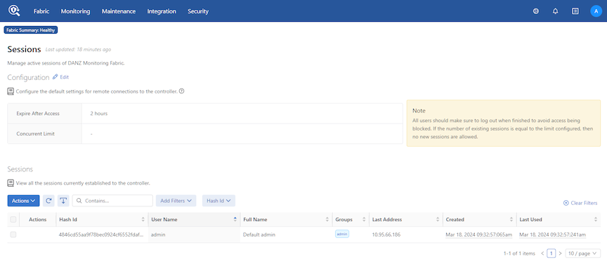 The page displays the sessions currently established. To forcibly end a session, select Delete Security Sessions from the Actions control for the session.Note: All users should log out when finished to avoid blocked access. No new sessions are allowed if the number of existing sessions equals the limit configured.
 - Under Configuration, click Edit to configure the default settings for remote connections to the Controller.
Figure 13. Security Sessions Configurations 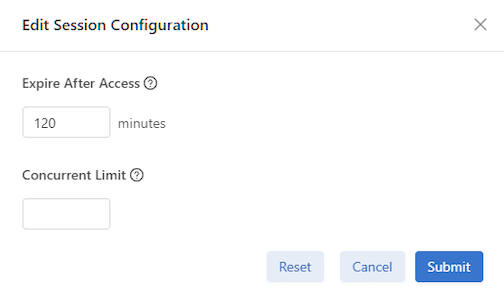
This dialog lets you set an expiration time for sessions and the maximum number of sessions allowed for each user.
Tip: Use the Reset button to clear the settings and return to the default values, if required.
Managing and Viewing Logs
By default, the DANZ Monitoring Fabric (DMF) fabric switches send syslog messages to both the active and standby Controllers. Syslog messages are disk persistent and only removed based on time and rotation policy.
After configuring an external syslog server, the Controllers send the syslog messages to the external server and keep a local copy of the syslog messages on the Controller. When configuring multiple external syslog servers, DMF sends the syslog messages to every server. Physical switch logs can be sent directly to an external syslog server instead of sending the logs to the DMF Controller.
Sending Logs to a Remote Syslog Server
With the external Syslog server configured and the logging switch-remote option enabled, the fabric switches send Syslog messages only to the configured external Syslog servers but not to the Controllers. When the logging switch-remote option is enabled, the Controller does not have a local copy of the switch logs.
The Controllers do not share their syslog with the other Controller in the cluster. In other words, the active Controller does not send its syslog messages to the standby Controller, and the standby Controller does not share its syslog messages with the active Controller. Access the individual Controller logs from either the active or standby node.
Using the GUI to Configure Remote Logging
- Select from the main menu and click Remote Logging.
Figure 14. Maintenance Logging 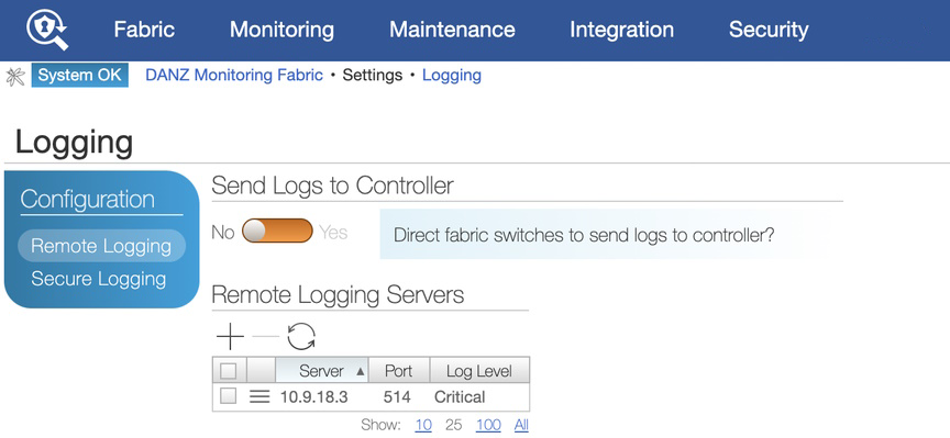
- To enable remote logging, identify a remote syslog server by clicking the Provision control (+) in the Remote Servers table.
Note: Enabling remote logging causes syslog messages to be sent directly from the fabric switches to the specified server, bypassing the Controller. As a result, the Switch Light log files will not be available on the local Controller for analysis using the Analytics option.
Figure 15. Create a Remote Server 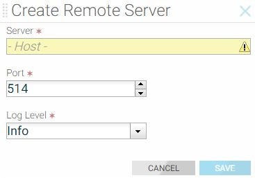
Using the CLI to Configure Remote Logging
To configure the syslog server for a Controller node, enter the logging remote command using the following syntax:
..code-block:: none
logging remote <ip-address>
controller-1(config)# logging remote 192.168.100.1
This example exports the syslog entries from the Controller node to the syslog server at IP address 192.168.100.1.
Viewing Log Files on the Controller
- audit: Show audit file contents
- controller: Show log contents for the Controller floodlight process
- remote: Show remote logs
- switch switch: Show logs for the specified switch
- syslog: Show syslog file contents
- web-access: Show content of the web server access log
- web-error: Show content of the web server error log
controller-1> show logging controller
floodlight: WARN [MdnsResponder:Network Queue Processing Thread] ZTN4093: 1CC38M2._gm_idrac._tcp.
local.
2018-03-26T04:03:17.900-07:00 invalid/unrecognized SRV name 1CC38M2._gm_idrac._tcp.local.
floodlight: WARN [MdnsResponder:Network Queue Processing Thread] ZTN4093: 1CC38M2._gm_idrac._tcp.
local.
2018-03-26T04:03:17.900-07:00 invalid/unrecognized SRV name 1CC38M2._gm_idrac._tcp.local.
floodlight: WARN [MdnsResponder:Network Queue Processing Thread] ZTN4093: 1CC38M2._gm_idrac._tcp.
local.
2018-03-26T04:03:17.900-07:00 invalid/unrecognized SRV name 1CC38M2._gm_idrac._tcp.local.
...
controller-1>
Administrative Activity Logs
- CLI commands entered
- Login and logout events
- Queries to the REST server
- RPC message summaries between components in the Controller
CLI Commands
grep with the show logging command to see the local accounting logs, as in the following example:
controller-1# show logging controller | grep "cmd_args"
Sep 4 21:23:10 BT2 floodlight: INFO [net.bigdb.auth.AuditServer:Dispatcher-3] AUDIT EVENT: bigcli.
command application_id=bigcli cmd_args=enable
Sep 4 21:23:10 BT2 floodlight: INFO [net.bigdb.auth.AuditServer:Dispatcher-4] AUDIT EVENT: bigcli.
command application_id=bigcli cmd_args=configure
Sep 4 21:23:16 BT2 floodlight: INFO [net.bigdb.auth.AuditServer:Dispatcher-3] AUDIT EVENT: bigcli.
command application_id=bigcli cmd_args=bigtap policy policy3
Sep 4 21:23:20 BT2 floodlight: INFO [net.bigdb.auth.AuditServer:Dispatcher-6] AUDIT EVENT: bigcli.
command application_id=bigcli cmd_args=bigchain chain hohoh
Sep 4 21:23:22 BT2 floodlight: INFO [net.bigdb.auth.AuditServer:Dispatcher-3] AUDIT EVENT: bigcli.
command application_id=bigcli cmd_args=ext
Sep 4 21:23:24 BT2 floodlight: INFO [net.bigdb.auth.AuditServer:Dispatcher-3] AUDIT EVENT: bigcli.
command application_id=bigcli cmd_args=configure
Sep 4 21:23:30 BT2 floodlight: INFO [net.bigdb.auth.AuditServer:Dispatcher-5] AUDIT EVENT: bigcli.
command
controller-1(config)# aaa accounting exec default start-stop local
controller-1(config)# aaa accounting exec default start-stop {local [group tacacs+] | [group
radius]}
controller-1# show logging controller | grep AUDIT
If accounting is remote only, consult the administrator for the TACACS+ server for more information.
REST API Logging
Starting with the DANZ Monitoring Fabric 8.4 release, the REST API body can be logged into the audit.log file. Before the 8.4 release, REST API calls from GUI or REST clients were logged in the audit.log file without the request's data (or) body. In this release, the data and body of the REST API call can be logged.
aaa audit-logging log-request-leaf-values record-all-request-values
controller-1# config
controller-1(config)# aaa audit-logging log-request-leaf-values record-all-request-values
controller-1(config)#
no form of the command:
no aaa audit-logging log-request-leaf-values record-all-request-values
2022-11-16T12:18:05.106-08:00 floodlight: INFO LOCLAUD1001: AUDIT EVENT: DB_QUERY auth-
description="session/9d0a66315f7d9e0df8f2478fe7c0b3d77cec25e865e4e135f0f9e28237570b70"
user="admin" remote-address="fd7a:629f:52a4:20d0:1ca8:28ed:6f59:cd47" session-id=
"9d0a66315f7d9e0df8f2478fe7c0b3d77cec25e865e4e135f0f9e28237570b70" operation="REPLACE"
uri="https://[fdfd:5c41:712d:d080:5054:ff:fe57:5dba]/api/v1/data/controller/os/config/
global/snmp" http-method="PUT" request-leaf-values="{"contact":"Arista","location":"HQ",
"trap-enabled":false,"user[name=\"cvml\"]/auth-passphrase":"AUTH-STRING","user[name=\
"cvml\"]/name":"cvml","user[name=\"cvml\"]/priv-passphrase":"PRIV-STRING","user[name=\
"cvml\"]/priv-protocol":"aes"}" code="204"
controller-# show run aaa
! aaa
aaa accounting exec default start-stop local
aaa audit-logging log-request-leaf-values record-all-request-values
controller-1#
Restricting Size of REST API Body
rest-api max-body-size <>
controller-1(config)# rest-api max-body-size
<max-body-size> Integer between 16384 to max integer size
controller-1(config)# rest-api max-body-size
controller-1(config)# rest-api max-body-size 16384
controller-1(config)#
no form of the command:
no rest-api max-body-size <>
Syslog Over TLS
This section describes how Syslog over TLS is implemented in DANZ Monitoring Fabric (DMF) and the configuration required to implement this feature.
Overview
- Impersonation: An unauthorized sender may send messages to an authorized receiver, or an unauthorized receiver may try to deceive a sender.
- Modification: An attacker may modify a syslog message in transit to the receiver.
- Disclosure: An unauthorized entity could examine the contents of a syslog message. TLS, when used as a secure transport, reduces these threats by providing the following functionality.
- Authentication counters impersonation.
- Integrity-checking counters modifications to a message on a hop-by-hop basis.
- Confidentiality works to prevent disclosure of message contents.
Starting from DMF Release 8.4, syslog over TLS is supported only for communication from Controllers to remote syslog servers. Switches and managed appliances such as Recorder Nodes and Service Nodes support plain unencrypted UDP-based syslog messages. To enable syslog over TLS on the Controller,refer to the next section.
Configuration
Creating a Support Bundle
A collection of running configuration and log files is critical to understanding the fabric behavior when the fabric is in a faulty state.
The DANZ Monitoring Fabric (DMF) CLI provides the commands to automate the collecting, archiving, and uploading of critical data. These commands cover all devices of the DMF fabric, such as Controllers, switches, DMF Service Node, and DMF Recorder Node.
controller-1> enable
controller-1# configure
controller-1(config)# service
controller-1(config-service)# support auto-upload
Enabled diagnostic data bundle upload
Use "diagnose upload support" to verify upload server connectivity
controller-1# show run service
! service
service
support auto-upload
controller-1#
controller-1# support
Generating diagnostic data bundle for technical support. This may take several minutes...
Support Bundle ID: SGPVW-BZ3MM
Switchlight collection completed after 14.2s. Collected 1 switch (8.56 MB)
Local cli collection completed after 38.2s. Collected 75 commands (0.32 MB)
Local rest collection completed after 0.1s. Collected 3 endpoints (0.43 MB)
Local bash collection completed after 10.0s. Collected 127 commands (4.74 MB)
Local file collection completed after 15.5s. Collected 39 paths (1753.31 MB)
Cluster collection completed after 138.2s. Collected 1 node (1764.50 MB)
Collection completed. Signing and compressing bundle...
Support bundle created successfully
00:04:03: Completed
Generated Support Bundle Information:
Name : anet-support--DMF-Controller--2020-11-24--18-31-39Z--SGPVW-BZ3MM.tar.gz
Size : 893MB
File System Path : /var/lib/floodlight/support/anet-support--DMF-Controller--2020-11-24--18-31-39Z--
SGPVW-BZ3MM.tar.gz
Url : https://10.2.1.103:8443/api/v1/support/anet-support--DMF-Controller--2020-11-24--
18-31-39Z--SGPVW-BZ3MM.tar.gz
Bundle id : SGPVW-BZ3MM
Auto-uploading support anet-support--DMF-Controller--2020-11-24--18-31-39Z--SGPVW-BZ3MM.tar.gz
Transfer complete, finalizing upload
Please provide the bundle ID SGPVW-BZ3MM to your support representative.
00:00:48: Completed
controller-1#
show support command shows the status of the automatic upload.
controller-1# show support
# Bundle                                                                   Bundle id    Size   Last modified                   Upload status
- |----------------------------------------------------------------------- |----------- |----- |------------------------------ |---------------- |
1 anet-support--DMF-Controller--2020-11-24--18-31-39Z--SGPVW-BZ3MM.tar.gz  SGPVW-BZ3MM  893MB  2020-11-24 18:35:46.400000 UTC  upload-completed
diagnose upload support command to verify the reachability and health of the server used to receive the support bundle. Below is an example output of checks performed when running the command. When a support bundle upload fails, use the command to identify the possible causes.
controller-1# diagnose upload support
Upload server version: diagus-master-43
Upload diagnostics completed successfully
00:00:02: Completed
Check : Resolving upload server hostname
Outcome : ok
Check : Communicating with upload server diagnostics endpoint
Outcome : ok
Check : Upload server healthcheck status
Outcome : ok
Check : Upload server trusts authority key
Outcome : ok
Check : Signature verification test
Outcome : ok
Check : Resolving objectstore-accelerate hostname
Outcome : ok
Check : Resolving objectstore-direct hostname
Outcome : ok
Check : Communicating with objectstore-accelerate
Outcome : ok
Check : Communicating with objectstore-direct
Outcome : ok
controller-1#
controller-1# upload support anet-support--DMF-Controller--2020-11-24--18-31-39Z--SGPVW-BZ3MM.tar.gz
The software provides the following options to reduce the amount of log entries collected in the support bundle:
controller-1# support
 logs-since-days         Generate diagnostic data bundle
 sequential              Use sequential (non-parallel) fallback collection mode, which will be slower but use fewer resources.
 skip-cluster            Skip cluster information from the collection.
 skip-jfr-dump           Skip creating JFR information during collection.
 skip-recorder-nodes     Skip Recorder Nodes information from the collection.
 skip-service-nodes      Skip service nodes information from the collection.
 skip-switches           Skip switches information from the collection.
 switch                  Copy a switch core dump
<Command-end>            <cr>: Return to execute command
 ;                       command separator
 |                       pipe to command
 >                       redirect
controller-1#
NIST 800-63b Password Compliance
This feature activates password compliance for local accounts on DANZ Monitoring Fabric (DMF) devices (Controller, switches, DMF Service Node, Arista Analytics Node, and DMF Recorder Node). The NIST 800-63b feature enforces that any newly chosen password fulfills the following requirements:
- The password needs to be at least 8 characters long.
- The password is not a known compromised password.
Configuration
The NIST-800-63b compliance mode needs to be set separately on the Controller and the Arista Analytics Node to enforce password compliance for the entire DANZ Monitoring Fabric (DMF) cluster.
Controller(config)# aaa authentication password-compliance nist-800-63b
Warning: A password compliance check has been enabled. This enforces compliance
Warning: rules for all newly chosen passwords, but it doesn't retroactively
Warning: apply to existing passwords. Please choose new passwords for
Warning: all local users, managed appliances, switches, and the recovery user.
Controller(config)# no aaa authentication password-compliance
FIPS versions always enforce NIST 800-63b password compliance by default unless explicitly configured not to do so.
Controller(config)# aaa authentication password-compliance no-check
Controller(config)# show running-config aaa
! aaa
aaa authentication password-compliance nist-800-63b
Controller# configure
Controller(config)# user admin
Controller(config-user)# password <nist-compliant-password>
Controller(config)# service-node <service-node-name>
Controller(config-service-node)# admin password <nist-compliant-password>
Controller(config)# recorder-node <recorder-name>
Controller(config-packet-recorder)# admin password <nist-compliant-password>
Controller(config)# switch <switch-name>
Controller(config-switch)# admin password <nist-compliant-password>
Custom Password Compliance
This feature activates password compliance for local accounts on DANZ Monitoring Fabric (DMF) devices (Controller, switches, DMF Service Node, Arista Analytics Node, and DMF Recorder Node).
DMF supports custom password requirements for local users.
aaa authentication password-compliance custom-check
controller-1(config)# aaa authentication password-compliance custom-check
Warning: A password compliance check has been enabled. This enforces compliance
Warning: rules for all newly chosen passwords, but it doesn't retroactively
Warning: apply to existing passwords. Please choose new passwords for
Warning: all local users, managed appliances, switches, and the recovery user.
controller-1(config)#
no form of the command:
no aaa authentication password-compliance custom
controller-1(config)# aaa authentication password-requirement
max-repeated-characters the maximum number of repeated characters allowed
max-sequential-characters the maximum number of sequential characters allowed
minimum-length the minimum required length for passwords
minimum-lowercase-letter the minimum number of lowercase characters required
minimum-numbers the minimum number of numerical characters required
minimum-special-characters the minimum number of special characters required
minimum-uppercase-letter the minimum number of uppercase characters required
reject-known-exposed-passwords check the password against known exposed passwords
controller-1(config)# aaa authentication password-requirement
controller-1(config)# aaa authentication password-requirement minimum-length 10
controller-1(config)# aaa authentication password-requirement minimum-numbers 1
controller-1(config)# aaa authentication password-requirement max-repeated-characters 2
controller-1# conf
controller-1(config)# user customPW
controller-1(config-user)# password admin
Error: the password needs to be at least 10 characters long
controller-1(config-user)#
controller-1# show run aaa authentication
! aaa
aaa authentication password-compliance custom-check
aaa authentication password-requirement max-repeated-characters 2
aaa authentication password-requirement minimum-length 10
aaa authentication password-requirement minimum-numbers 1
controller-1#
no form of the commands:
controller-1(config)# no aaa authentication password-requirement minimum-length 10
controller-1(config)# no aaa authentication password-requirement minimum-numbers 1
controller-1(config)# no aaa authentication password-requirement max-repeated-characters 2
Switch/Managed Appliance Management Interfaces Not Mirroring Controller Management Interface ACLs
Use this feature to configure Access Control Lists (ACLs) on a managed device that do not directly reflect the ACLs configured on the Controller.
Specifically, a user can override the user-configured ACLs on the Controller (generally inherited by the managed devices) so that ACLs allowing specific types of traffic from the Controller only are pushed to managed devices.
The user performs this action on a per-managed-device basis or globally for all managed devices on the CLI. The Controller and analytics node are excluded from receiving this configuration type (when performed globally).
The feature introduces a new CLI mode to address this configuration type on the Controller. That is, the configuration used for pushing to all managed devices exclusively (excluding the Controller) unless overrides exist.
A managed device is a device whose life cycle ZTN manages.
The total set of managed devices is as follows:
-
Managed Appliances
-
Service Node
-
Recorder Node
-
-
Switches
-
SWL
-
EOS
-
Configuration using the CLI
Configure the following on the Controller to enforce Intra-Fabric Only Access (IFOA) for the API service (i.e., port 8443) on all managed devices.
C1> en
C1# conf
C1(config)# managed-devices
C1(config-managed-devices)# access-control
C1(config-managed-devices-access)# service api
C1(config-managed-devices-access-service)# intra-fabric-only-access
Reminder: IP address/method of the management interface cannot be changed,
when a service has intra-fabric only access enforced.
Several services can have IFOA enforced on them. The list of services and their corresponding ports are shown in the table below. An ✘ mark means enforcing IFOA on that port on that managed device type is not supported.
Conversely, a ✔ mark means enforcing IFOA on that port on that managed device type is supported. There may be some information beside the ✔ mark indicating what runs on that port on the managed device.
| Protocol | Service Node | Recorder Node | SWL | EOS |
|---|---|---|---|---|
| SSH (22, TCP) | ✔ | ✔ | ✔ | ✔ |
| WEB (80, TCP) | ✘ | ✘ | ✔ (SLRest, plain-text) | ✔ (cAPI) |
| HTTPS (443, TCP) | ✘ | ✔ (nginx reverse proxies to 1234, for the stenographer) | ✘ (SLRest, encrypted) | ✔ |
| API (8443, TCP) | ✔ (BigDB) | ✔ (BigDB) | ✔ (BigDB) | ✘ |
C1(config)# switch switch-name
C1(config-switch)# access-control
C1(config-switch-access)# inheritance-control override-global
C1(config-switch-access)# service api
C1(config-switch-access-service)# no intra-fabric-only-access
As illustrated below, push a similar configuration for the managed appliances, i.e., the Recorder and Service nodes.
Recorder Node
C1(config)# recorder-node device rn1
C1(config-recorder-node)#
C1(config-recorder-node)# access-control
C1(config-recorder-node-access)# inheritance-control override-global
C1(config-recorder-node-access)# service api
C1(config-recorder-node-access-service)# no intra-fabric-only-access
Service Node
C1(config)# service-node sn1
C1(config-service-node)#
C1(config-service-node)# access-control
C1(config-service-node-access)# inheritance-control override-global
C1(config-service-node-access)# service api
C1(config-service-node-access-service)# no intra-fabric-only-access
It is also possible to push a configuration that does not override the entire configuration under managed devices but instead merges with it on a per-service basis, for example:
C1(config)# switch core1
C1(config-switch)# access-control
C1(config-switch-access)# inheritance-control override-global
C1(config-switch-access)# service api
C1(config-switch-access-service)# no intra-fabric-only-access
This action will merge the global/default config specified under the config-managed-devices CLI submode with the config set for this specific managed device (in this case, the device is a switch, and its name on the Controller is core1).
CLI Show Commands
There are several helpful show commands.
When merging the global/default access-control configuration with the device-specific configuration, understanding the effective configuration (the configuration used in generating the appropriate ACLs) may not be obvious. To see the effective configuration for a specific device, perform the following command:
C1(config)# show effective-config switch core1
! switch
switch core1
access-control
!
service api
intra-fabric-only-access
While displaying the managed device's effective configuration, check the running-config generated by ZTN (the configuration sent to the device), confirming the configuration pushed to the managed device.
C1(config)# show service-node rn1 running-config
.
.
.
interface ma1 acl subnet 10.243.254.20/32 proto tcp port 8443 accept
interface ma1 acl subnet fe80::5054:ff:fef8:b844/128 proto tcp port 8443 accept
interface ma1 acl subnet 0.0.0.0/0 proto tcp port 8443 drop
interface ma1 acl subnet ::/0 proto tcp port 8443 drop
interface ma1 acl subnet ::/0 proto udp port 161 accept
interface ma1 acl subnet 0.0.0.0/0 proto udp port 161 accept
interface ma1 acl subnet 0.0.0.0/0 proto udp port 161 drop
interface ma1 acl subnet ::/0 proto udp port 161 drop
interface ma1 acl subnet 10.243.254.20/32 proto tcp port 22 accept
interface ma1 acl subnet fe80::5054:ff:fef8:b844/128 proto tcp port 22 accept
interface ma1 acl subnet ::/0 proto tcp port 22 accept
interface ma1 acl subnet 0.0.0.0/0 proto tcp port 22 accept
interface ma1 acl subnet 0.0.0.0/0 proto tcp port 22 drop
interface ma1 acl subnet ::/0 proto tcp port 22 drop
interface ma1 acl default accept
.
.
.
Recorder Nodes
show effective-config recorder-node rn1show recorder-node rn1 running-config
show effective-config service-node rn1show service-node rn1 running-config
Limitations
The main limitation of this feature is the inability to change the management interface's IP address (on the CLI) once enforcing IFOA for any of the services on any managed devices so that the Controller does not inadvertently get locked out from the managed devices.
Recovery Procedure
This section describes the recovery procedure when one or both Controllers go down.
Recovery from a Single Controller Failure
Recovery from a Dual Controller Failure
Procedure