Using the CloudEOS and vEOS Router on Arista Appliance (DCA-200-vEOS)
Overview
Hardware
The CloudEOS and vEOS Router appliance has the following hardware configuration:
- 2 sockets with 10 CPU cores each. The server is configured for optimal CloudEOS and vEOS Router performance. For example Hyperthreading has been turned off.
- 64 GB memory.
- Two 2 x 10G SFP+ NIC cards for a total of 4 10G NIC ports for data traffic.
- 2 x 1G ports (eno1 and eno2) for management.
- 2 x 1G ports (eno3 and eno4) NOT used by CloudEOS and vEOS launcher scripts.
- iDRAC
Interfaces
The below figure shows all the interfaces on the appliance.
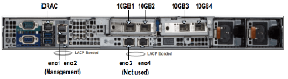
Management Interfaces
As shown in the above figure, the appliance has 4 physical 1G ports --- eno1/2/3/4. eno1 and eno2 are aggregated to a bonded interface device0 in 802.3ad mode. So they need to be connected to one or more network devices supporting Link Aggregation Control Protocol (LACP). Bonded interface device0 is connected to a Linux bridge named devicebr internally. CloudEOS and vEOS launcher script will setup CloudEOS and vEOS Router with connecting their management interfaces to devicebr. eno3 and eno4 are aggregated to bonded interface cluster0 and cluster0 is connected to Linux bridge clusterbr in the same way. However, they are not used for CloudEOS and vEOS Router setup.
Data Traffic Interfaces
As shown in the above figure, the appliance has 4 physical 10G ports --- 10GB1/2/3/4 those are configured in SR-IOV mode. Each port is partitioned into 32 SR-IOV Virtual Functions to provide a total of 128 virtual interfaces for CloudEOS and vEOS instances on the appliance. You may optionally configure a VLAN to be used for each virtual interface. The VLAN configuration allows separation of broadcast domain for traffic in and out of each physical port. The VLAN tag handling is done by SRIOV NIC and it is transparent to the CloudEOS and vEOS Router. Please note that for performance reasons, the CloudEOS and vEOS launcher script creates CloudEOS and vEOS Router with all of its CPU cores and memory from the same NUMA node. Therefore, all required CPU resources for a CloudEOS and vEOS Router need to be available on one socket. If required, resources for launching a new CloudEOS and vEOS Router are split across two sockets, CloudEOS and vEOS launcher will not be able to launch the CloudEOS and vEOS Router. In such scenario, user may need to reconfigure the existing VMs and/or reduce resource requirements of the new VM to fit within a NUMA node.
Appliance Setup
- Setup Management Connections
- Connect iDRAC (IPMI) to a network device.
- Connect eno1 and eno2 to a network device supporting LACP.
- Make sure the DHCP server is setup properly.
- After appliance boot up, iDRAC and devicebr (the management bridge interface) will get it's DHCP assigned IP addresses.
- For DHCP based IP address setup, refer to section 2.5.1 - DHCP Based IP Address Setup in Arista CloudVision Appliance Quick Start Guide.
- For Manual based IP address, refer to section 2.5.2 - Manual IP Address Setup in Arista CloudVision Appliance Quick Start Guide. After configuring IP addresses manually for management interfaces, reboot the appliance instead of just restarting the network-service, because the appliance setup scripts for DCA-200-vEOS takes effect only during the reboot.
- There are multiple ways to connect to the appliance:
- SSH to devicebr DHCP address.
- Web access to iDRAC https://<hostname or IP of iDRAC using Google Chrome or any other web browser.
- Use the terminals connected to VGA and other peripherals if DHCP addresses of management interfaces are not known.
- Login to the appliance using username:root (password:arista). Change appliance username/password appropriately as needed, by referring to Chapter 3 - Accessing CloudVision Appliance in Arista CloudVision Appliance Quick Start Guide.
CloudEOS and vEOS Router Installation
Supported vEOS Router Configurations

Launching/Removing/Query CloudEOS and vEOS Router
In the above figure in “Interfaces” section shows the rear view of the appliance and ethernet ports (10GB1/2/3/4) the CloudEOS and vEOS launcher script references. The ethernet ports in the CloudEOS and vEOS Router are virtual ethernet ports connected to one of the 10GB1/2/3/4 ports. VLANs are configured on each interface when installing CloudEOS and vEOS. The VLAN tagging is done by the SRIOV NICs. Note, that the connected networking devices need to have the same VLANs configured on the trunk port.
The appliance are shipped with a version of CloudEOS and vEOS Router image which is found in /data/tools. If you want to install the latest CloudEOS and vEOS Router image download desired CloudEOS.qcow2 version from Arista.com to the appliance to another directory.
The CloudEOS and vEOS launcher is a python script named dca-200-veos-setup-vm.py which is found in /data/tools directory as shown.
Router# ./dca-200-veos-setup-vm.py --help
usage: dca-200-veos-setup-vm.py [-h] [-n VMNAME] [-m IMAGE] [-d]
[-i [INTERFACE [INTERFACE ...]]] [-s MEMORY]
[-c CORES] [-r [REMOVE [REMOVE ...]]] [-q]

Create/Remove VEOS instances

optional arguments:
-h, --helpshow this help message and exit
-n VMNAME, --name VMNAME
Name of the VEOS VM
-m IMAGE, --image IMAGE
Qcow2 image name to use for launching the VM
-d, --debug Print detailed debug info
-i [INTERFACE [INTERFACE ...]], --interface [INTERFACE [INTERFACE ...]]
Interfaces and optional vlans/mac. The interfaces must
be listed in guest interfaces order. The interfase can
be specified either in PCI address format (using lspci
command) Or 10GB1/2/3/4. For example: '-i
10GB1,vlan=10 10GB2 10GB3,vlan=40' or '-i
3b:10.2,vlan=50 3b:10.3,vlan=10 af:10.2 af:10.3'
-s MEMORY, --memory MEMORY
Memory in Gbytes to assign to VM. Default is 4 Gb
-c CORES, --cores CORES
Number of Cores to assign to VM. Default is 4 cores
-r [REMOVE [REMOVE ...]], --remove [REMOVE [REMOVE ...]]
Remove VMs
-q, --query Query info about configured VMs
Example
Below is an example of commands used to launch a vEOS VMs with core count of 4 (default), 4GB memory (default), and with 4 ethernet interfaces.
Router# ./dca-200-veos-setup-vm.py -n veos-router1 -m /tmp/CloudEOS.qcow2 -i 10GB2,vlan=50 10GB1,vlan=10 10GB3,vlan=100 af:10.0,vlan=200
Extracting info for existing VMs: ['']
Total count is: 20, reserved for hypervisor: 2, Total Available: 18
Used CPU count is 0, Free cores 18
intfList is: ['10GB2,vlan=50', '10GB1,vlan=10', '10GB3,vlan=100', 'af:10.0,vlan=200']
Used CPU count is 0, Free cores 18
Free core set on Node 0 : [2, 4, 6, 8, 10, 12, 14, 16, 18]
CPU core used are:[2, 4, 6, 8]
Using PCI interfaces for new VM veos-router1:
('veos-router1', 'et1') --> 10GB2 PCI address: 3b:10.0 vlan 50 mac None
('veos-router1', 'et2') --> 10GB1 PCI address: 3b:10.1 vlan 10 mac None
('veos-router1', 'et3') --> 10GB3 PCI address: af:10.1 vlan 100 mac None
('veos-router1', 'et4') --> 10GB4 PCI address: af:10.0 vlan 200 mac None
The following observations are from the above example:
- Without specifying number of cores, VM will be created with 4 cores by default. vEOS launcher picks core 2,4,6,8 on NUMA node0 for veos-router1.
- A different image “/tmp/CloudEOS.qcow2” than the default vEOS Router image (/data/tools/CloudEOS.qcow2) is specified
- Interfaces MUST be specified in VM interface order (the physical 10GB port eth1, eth2.. in VM) in either 10GBx or PCI address format. In the above example we used both 10GBx format as well as PCI address format to specify 4 interfaces. The interfaces are configured on different VLANs
- Launcher script will print out the guest interface mapping to host 10GB interfaces.
If an error occurs while creating a new VM using vEOS launcher, then refer to the Troubleshooting section of the chapter for more information.
The dca-200-veos-setup-vm.py script is used to remove the running VMs. The example below shows how to remove two existing VMs.
Router# ./dca-200-veos-setup-vm.py -r veos-router1 veos-router2
Cleaning up VM:veos-router1
Cleaning up VM:veos-router2
Besides launching/removing functionality, dca-200-veos-setup-vm.py script also provides a query command to print the current status of the running VMs. The output includes
- List of running VMs
- Mapping of running VM interfaces to host interfaces
- Mapping of VM CPUs to host CPUs
Below is an example output:
Router# ./dca-200-veos-setup-vm.py -q
Extracting info for existing VMs: ['veos-router1', 'veos-router2']
Total count is: 20, reserved for hypervisor: 2, Total Available: 18
Used CPU count is 8, Free cores 10
VM veos-router1 :
interfaces:
et1 --> 10GB2 PCI address: 3b:10.0 vlan 50 mac 52:54:00:d4:f4:46
et2 --> 10GB1 PCI address: 3b:10.1 vlan 10 mac 52:54:00:d8:a9:50
et3 --> 10GB3 PCI address: af:10.1 vlan 100 mac 52:54:00:0c:0a:15
et4 --> 10GB4 PCI address: af:10.0 vlan 200 mac 52:54:00:20:4a:67
CPU Core Mapping:
0 --> 2
1 --> 4
2 --> 6
3 --> 8
VM veos-router2 :
interfaces:
et1 --> 10GB4 PCI address: af:10.2 vlan 50 mac 52:54:00:bb:ab:f1
et2 --> 10GB3 PCI address: af:10.3 vlan 10 mac 52:54:00:58:f7:2b
CPU Core Mapping:
0 --> 10
1 --> 12
2 --> 14
3 --> 16
Available free cores:3 5 7 9 11 13 15 17 18 19
Accessing CloudEOS and vEOS
For virtual console access there are two options:
- On the appliance virsh console <vm_name>
- Launch browser based VM management tool kimchi to edit/view/console-access of the VMs at https://<management_ip>:8001.
Troubleshooting
PCI Addresses for Virtual Functions
[root@cv ~]# ethtool -i 10GB1 | grep bus
bus-info: 0000:3b:00.1
[root@cv ~]# ethtool -i 10GB2 | grep bus
bus-info: 0000:3b:00.0
[root@cv ~]# ethtool -i 10GB3 | grep bus
bus-info: 0000:af:00.1
[root@cv ~]# ethtool -i 10GB4 | grep bus
bus-info: 0000:af:00.0
[root@cv ~]# lspci | grep Ethernet
04:00.0 Ethernet controller: Broadcom Inc. and subsidiaries NetXtreme BCM5720 Gigabit Ethernet PCIe
04:00.1 Ethernet controller: Broadcom Inc. and subsidiaries NetXtreme BCM5720 Gigabit Ethernet PCIe
3b:00.0 Ethernet controller: Intel Corporation Ethernet 10G 2P X520 Adapter (rev 01)⇐ 10GB2 PF
3b:00.1 Ethernet controller: Intel Corporation Ethernet 10G 2P X520 Adapter (rev 01)⇐ 10GB1 PF
3b:10.0 Ethernet controller: Intel Corporation 82599 Ethernet Controller Virtual Function (rev 01)⇐ 10GB2 VF
3b:10.1 Ethernet controller: Intel Corporation 82599 Ethernet Controller Virtual Function (rev 01)⇐ 10GB1 VF
3b:10.2 Ethernet controller: Intel Corporation 82599 Ethernet Controller Virtual Function (rev 01)
3b:10.3 Ethernet controller: Intel Corporation 82599 Ethernet Controller Virtual Function (rev 01)
...
3b:17.6 Ethernet controller: Intel Corporation 82599 Ethernet Controller Virtual Function (rev 01)
3b:17.7 Ethernet controller: Intel Corporation 82599 Ethernet Controller Virtual Function (rev 01)
5e:00.0 Ethernet controller: Broadcom Inc. and subsidiaries NetXtreme BCM5720 Gigabit Ethernet PCIe
5e:00.1 Ethernet controller: Broadcom Inc. and subsidiaries NetXtreme BCM5720 Gigabit Ethernet PCIe
af:00.0 Ethernet controller: Intel Corporation Ethernet 10G 2P X520 Adapter (rev 01)⇐ 10GB4 PF
af:00.1 Ethernet controller: Intel Corporation Ethernet 10G 2P X520 Adapter (rev 01)⇐ 10GB3 PF
af:10.0 Ethernet controller: Intel Corporation 82599 Ethernet Controller Virtual Function (rev 01)⇐ 10GB4 VF
af:10.1 Ethernet controller: Intel Corporation 82599 Ethernet Controller Virtual Function (rev 01)⇐ 10GB3 VF
af:10.2 Ethernet controller: Intel Corporation 82599 Ethernet Controller Virtual Function (rev 01)
af:10.3 Ethernet controller: Intel Corporation 82599 Ethernet Controller Virtual Function (rev 01)
...
af:17.6 Ethernet controller: Intel Corporation 82599 Ethernet Controller Virtual Function (rev 01)
af:17.7 Ethernet controller: Intel Corporation 82599 Ethernet Controller Virtual Function (rev 01)
[root@cv ~]# virsh nodedev-list | grep 3b_00_0 ⇐ PF PCI
pci_0000_3b_00_0
[root@cv ~]# virsh nodedev-dumpxml pci_0000_3b_00_0
<device>
<name>pci_0000_3b_00_0</name>
<path>/sys/devices/pci0000:3a/0000:3a:00.0/0000:3b:00.0</path>
<parent>pci_0000_3a_00_0</parent>
<driver>
<name>ixgbe</name>
</driver>
<capability type='pci'>
<domain>0</domain>
<bus>59</bus>
<slot>0</slot>
<function>0</function>
<product id='0x154d'>Ethernet 10G 2P X520 Adapter</product>
<vendor id='0x8086'>Intel Corporation</vendor>
<capability type='virt_functions' maxCount='63'>
<address domain='0x0000' bus='0x3b' slot='0x10' function='0x0'/> ⇐ VF PCI
<address domain='0x0000' bus='0x3b' slot='0x10' function='0x2'/>
<address domain='0x0000' bus='0x3b' slot='0x10' function='0x4'/>
<address domain='0x0000' bus='0x3b' slot='0x10' function='0x6'/>
<address domain='0x0000' bus='0x3b' slot='0x11' function='0x0'/>
<address domain='0x0000' bus='0x3b' slot='0x11' function='0x2'/>
<address domain='0x0000' bus='0x3b' slot='0x11' function='0x4'/>
<address domain='0x0000' bus='0x3b' slot='0x11' function='0x6'/>
<address domain='0x0000' bus='0x3b' slot='0x12' function='0x0'/>
<address domain='0x0000' bus='0x3b' slot='0x12' function='0x2'/>
<address domain='0x0000' bus='0x3b' slot='0x12' function='0x4'/>
<address domain='0x0000' bus='0x3b' slot='0x12' function='0x6'/>
<address domain='0x0000' bus='0x3b' slot='0x13' function='0x0'/>
<address domain='0x0000' bus='0x3b' slot='0x13' function='0x2'/>
<address domain='0x0000' bus='0x3b' slot='0x13' function='0x4'/>
<address domain='0x0000' bus='0x3b' slot='0x13' function='0x6'/>
<address domain='0x0000' bus='0x3b' slot='0x14' function='0x0'/>
<address domain='0x0000' bus='0x3b' slot='0x14' function='0x2'/>
<address domain='0x0000' bus='0x3b' slot='0x14' function='0x4'/>
<address domain='0x0000' bus='0x3b' slot='0x14' function='0x6'/>
<address domain='0x0000' bus='0x3b' slot='0x15' function='0x0'/>
<address domain='0x0000' bus='0x3b' slot='0x15' function='0x2'/>
<address domain='0x0000' bus='0x3b' slot='0x15' function='0x4'/>
<address domain='0x0000' bus='0x3b' slot='0x15' function='0x6'/>
<address domain='0x0000' bus='0x3b' slot='0x16' function='0x0'/>
<address domain='0x0000' bus='0x3b' slot='0x16' function='0x2'/>
<address domain='0x0000' bus='0x3b' slot='0x16' function='0x4'/>
<address domain='0x0000' bus='0x3b' slot='0x16' function='0x6'/>
<address domain='0x0000' bus='0x3b' slot='0x17' function='0x0'/>
<address domain='0x0000' bus='0x3b' slot='0x17' function='0x2'/>
<address domain='0x0000' bus='0x3b' slot='0x17' function='0x4'/>
<address domain='0x0000' bus='0x3b' slot='0x17' function='0x6'/>
</capability>
<iommuGroup number='30'>
<address domain='0x0000' bus='0x3b' slot='0x00' function='0x0'/>
</iommuGroup>
<numa node='0'/>
<pci-express>
<link validity='cap' port='0' speed='5' width='8'/>
<link validity='sta' speed='5' width='8'/>
</pci-express>
</capability>
</device>
CloudEOS and vEOS Launcher Debugging Functionalities
CloudEOS and vEOS launcher script provides the below mechanisms helping with debugging:
- CloudEOS and vEOS launcher error messages
- CloudEOS and vEOS launcher query command
[root@cv /data/tools]# ./dca-200-veos-setup-vm.py -n veos-router2 -m ./CloudEOS.qcow2 -i af:10.0,vlan=50 10GB3,vlan=10
Extracting info for existing VMs: ['veos-router1']
Total count is: 20, reserved for hypervisor: 2, Total Available: 18
Used CPU count is 4, Free cores 14
intfList is: ['af:10.0,vlan=50', '10GB3,vlan=10']
Error: Interface af:10.0 is already assigned to VM veos-router1
[root@cv /data/tools]# ./dca-200-veos-setup-vm.py -n veos-router5 -m ./CloudEOS.qcow2 -i 10GB4,vlan=20 10GB1,vlan=30
Extracting info for existing VMs: ['veos-router1', 'veos-router2', 'veos-router3', 'veos-router4']
Total count is: 20, reserved for hypervisor: 2, Total Available: 18
Used CPU count is 16, Free cores 2
intfList is: ['10GB4,vlan=20', '10GB1,vlan=30']
Free core set on Node 0 : [18]
Free core set on Node 1 : [19]
Not enough CPU cores available on any NUMA node to allocate 4 cores.
The above example shows when user tries to create a VM with 4 cores (by default), an error message points out there’s not enough CPU cores available on any NUMA. It also prints out current free cores on each NUMA node (core 18 on node0 and core 19 on node1). User may choose to reduce the number of cores for new instance or reprovision existing VMs to fit new VM in.
Appliance Setup Debugging
- dca-200-veos-test.sh
- dca-200-veos-test-nics.py
/data/imaging/dca-200-veos-test.sh checks things like hyperthreading, interface MTU and etc.
[root@cv /data/imaging]# ./dca-200-veos-test.sh
Device '10GB1' successfully disconnected.
Connection successfully activated (D-Bus active path: /org/freedesktop/NetworkManager/ActiveConnection/19)
Device '10GB2' successfully disconnected.
Connection successfully activated (D-Bus active path: /org/freedesktop/NetworkManager/ActiveConnection/20)
Device '10GB3' successfully disconnected.
Connection successfully activated (D-Bus active path: /org/freedesktop/NetworkManager/ActiveConnection/21)
Device '10GB4' successfully disconnected.
Connection successfully activated (D-Bus active path: /org/freedesktop/NetworkManager/ActiveConnection/22)
Appliance is correctly set for VEOS use
/data/imaging/dca-200-veos-test-nics.py creates 4 VMs and sends traffic among them to test NICs are setup properly for creating new VMs and sending traffic.
[root@cv /data/imaging]# ./dca-200-veos-test-nics.py -a -i /data/tools/CloudEOS.qcow2
Cleaning up VMs:['autoDut1']
Cleaning up VMs:['autoDut2']
Cleaning up VMs:['autoDut3']
Cleaning up VMs:['autoDut4']
Creating instance autoDut1
Creating instance autoDut2
Creating instance autoDut3
Creating instance autoDut4
Starting Traffic test on created VMs
Running Tests onautoDut1
Running Tests onautoDut2
Running Tests onautoDut3
Running Tests onautoDut4
All Tests finished Successfully
Cleaning up VMs:['autoDut1']
Cleaning up VMs:['autoDut2']
Cleaning up VMs:['autoDut3']
Cleaning up VMs:['autoDut4']
If there are error messages shown from the above two test scripts, user can run /data/imaging/dca-200-veos-setup.sh to re-setup the appliance. Note, The /data/imaging/dca-200-veos-setup.sh will reconfigure the interfaces and other parameters on the appliance and reboot the VMs, which may affect the running VMs to working properly and stop.
The appliance shipped should be in good condition, and quality checked stage, where setup and test scripts have already been run. So it is NOT recommended for customer to run /data/imaging/dca-200-veos-setup.sh without contacting Arista support.
Supported Transceivers
The 10G ethernet ports are tested using the following Arista transceivers:
- -10G-SR
- -10G-SRL
- -10G-LR
- -10G-AOC
- -10G-CR
Limitations
- There can be a maximum 32 virtual interfaces (virtual functions) on a physical interface.
- The optimization for NUMA may reduce the VMs that can be hosted on the appliance. You may need to reprovision existing VMs to leverage all the resources in case of resource fragmentation.
- DCA-200-vEOS starts supporting CVA upgrade from 2.1.2 to afterward releases.