Cable the Router
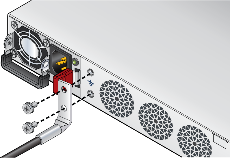
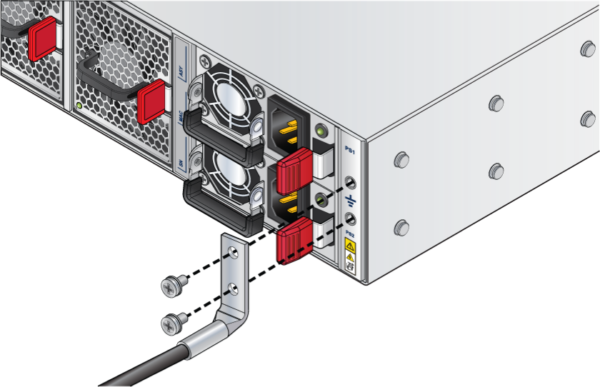
Grounding the Router
This section provides instructions for grounding the router.
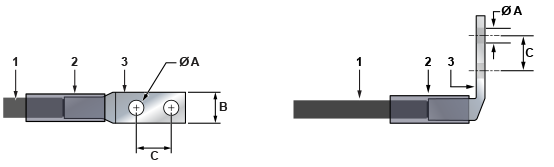
| 1 | Insulated cable | A | 1/4″ |
| 2 | Heat-shrink tubing | B | 1/2″ |
| 3 | Lug | C | 5/8″ |
- Ensure the rack is properly grounded and complies with ETSI EN 300 253.
- Ensure that there is a good electrical connection to the grounding point on the rack (no paint or isolating surface treatment).
- Attach the solder terminal lug to an 18 AWG minimum grounding cable, and connect it to the grounding point on the rear panel of the router.
- Tighten the screw to secure the lug to the grounding point.
- Connect the other end of the cable to the nearby grounded surface.
Connecting Power Cables
Power cords for use outside of the United States must be ordered separately. Ensure that the power cord is compliant with local and national electrical codes.
- Non-redundant configuration: Connect power to either of the two power supplies.
- Redundant power supply configuration: Connect power to both power supplies.
- Power down the router: Remove all power cords and wires from the power supplies.
Installation de cet équipement doit être conformes aux codes électriques locaux et nationaux. Si nécessaire, consulter les organismes de réglementation appropriés et des autorités de contrôle pour assurer la conformité.
Lire toutes les instructions d’installation avant de brancher le système à la source d’alimentation.
Cet équipement doit être mis à la terre. Ne jamais modifier le conducteur de terre.
Cet appareil requiert une protection contre les surintensités.
AC Power Supplies
- PWR-00619-01 (AWE-5310)
- PWR-00618-01 (AWE-5510)
The following image displays an AC power supply, including the power socket on the left side of the module. The AC power supply connects to a circuit that provides the required power, as specified in the Specifications section.
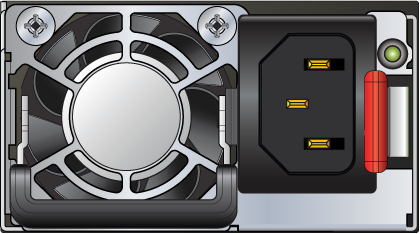
The power supplies require cables that comply with IEC-320 and have a C14 connector. The accessory kit provides two IEC-320 C13 to C14 power cables.
Connecting Serial and Management Cables
- RJ45 to DB9 serial adapter cable
- RJ45 Ethernet cable
Table 1 - RJ45 to DB9 Connections lists the pin connections of the RJ45 to DB9 adapter cable.
|
RJ45 |
DB9 |
RJ45 |
DB9 |
|||||
|---|---|---|---|---|---|---|---|---|
| RTS | 1 | 8 | CTS | GND | 5 | 5 | GND | |
| DTR | 2 | 6 | DSR | RXD | 6 | 3 | TXD | |
| TXD | 3 | 2 | RXD | DSR | 7 | 4 | DTR | |
| GND | 4 | 5 | GND | CTS | 8 | 7 | RTS | |
- Console (serial) port: Connect to a PC with the RJ45 to DB9 serial adapter cable. The router uses the following default settings:
- 9600 baud
- No flow control
- 1 stop bit
- No parity bits
- 8 data bits
- Ethernet management port: Connect to a 10/100/1000 management network with an RJ45 Ethernet cable.
- USB port: The two USB ports (Type-A and Type-C) may be used for software or configuration updates.
CAUTION: Excessive bending can damage interface cables.
Flexion excessive peut endommager les câbles d’interface.