Front Panel
This appendix displays the front panel of all switches covered by this guide.
Port-Speed Groups
Some of the devices shown in this appendix have ports that are grouped together to provide flexibility in configuring Ethernet speeds for the individual members of the group. The default configuration supports the maximum possible Ethernet speed and/or other lower, allowable speeds by the individual members of the group. Care must be taken when inserting optics for lower speed connectivity as further configuration may be required for the port(s) in the group to operate as desired.
For devices that support the port-speed group feature, the groups are called out in the relevant illustrations with the ports in the group identified.
Front Panels
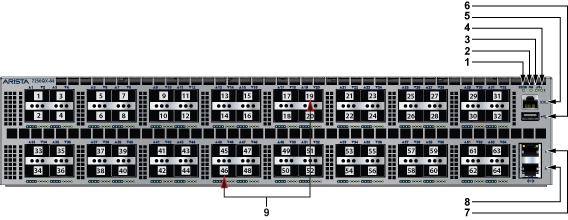
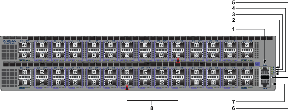
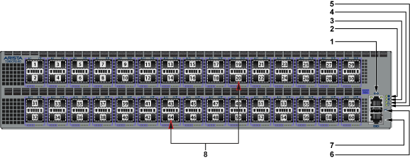
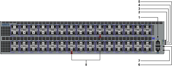
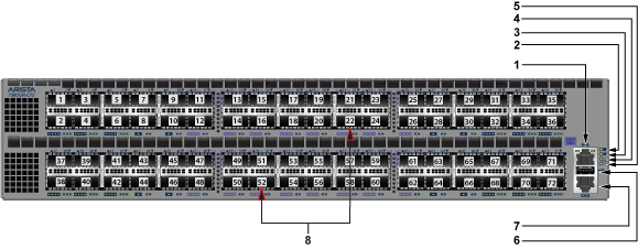
| 1 | System status LED | 4 | Power supply 2 status LED | 7 | Ethernet management port 1 |
| 2 | Fan tray status LED | 5 | Console serial port | 8 | Ethernet management port 2 |
| 3 | Power supply 1 status LED | 6 | USB port | 9 | Port numbers |
| 1 | System status LED | 4 | Power supply 2 status LED | 7 | Ethernet management port 1 |
| 2 | Fan tray status LED | 5 | Console serial port | 8 | Ethernet management port 2 |
| 3 | Power supply 1 status LED | 6 | USB port | 9 | Port numbers |
| 1 | System status LED | 4 | Power supply 2 status LED | 7 | Ethernet management port 1 |
| 2 | Fan tray status LED | 5 | Console serial port | 8 | Ethernet management port 2 |
| 3 | Power supply 1 status LED | 6 | USB port | 9 | Port numbers |
| 1 | System status LED | 4 | Power supply 2 status LED | 7 | Ethernet management port 1 |
| 2 | Fan tray status LED | 5 | Console serial port | 8 | Ethernet management port 2 |
| 3 | Power supply 1 status LED | 6 | USB port | 9 | Port numbers |
| 1 | System status LED | 4 | Power supply 2 status LED | 7 | Ethernet management port 1 |
| 2 | Fan tray status LED | 5 | Console serial port | 8 | Ethernet management port 2 |
| 3 | Power supply 1 status LED | 6 | USB port | Port numbers |
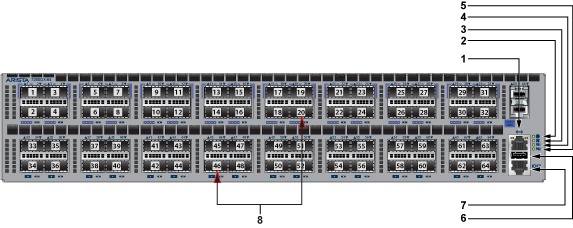
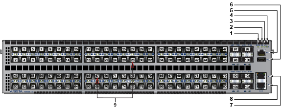
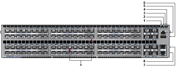
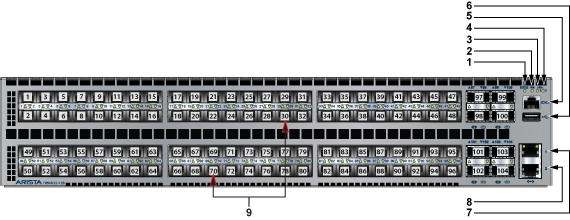
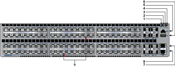
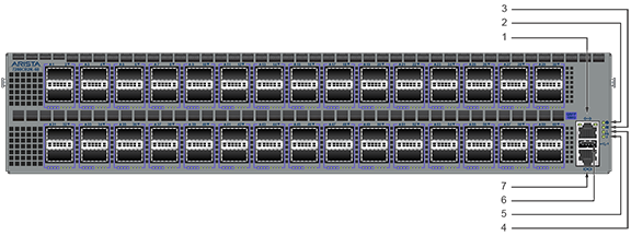
| 1 | Ethernet management port | 4 | Power supply 1 status LED | 7 | Console serial port |
| 2 | System status LED | 5 | Power supply 2 status LED | 8 | Port numbers |
| 3 | Fan tray status LED | 6 | USB port |
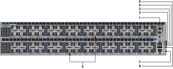
| 1 | Ethernet management port | 4 | Power supply 1 status LED | 7 | Console serial port |
| 2 | System status LED | 5 | Power supply 2 status LED | 8 | Port numbers |
| 3 | Fan tray status LED | 6 | USB port |
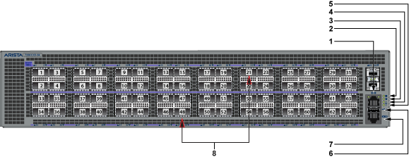
| 1 | Ethernet management port | 4 | Power supply 1 status LED | 7 | Console serial port |
| 2 | System status LED | 5 | Power supply 2 status LED | 8 | Port numbers |
| 3 | Fan tray status LED | 6 | USB port |
| 1 | Ethernet management port | 4 | Power supply 1 status LED | 7 | Console serial port |
| 2 | System status LED | 5 | Power supply 2 status LED | 8 | Port numbers |
| 3 | Fan tray status LED | 6 | USB port |
| 1 | Ethernet management port | 4 | Power supply 1 status LED | 7 | Console serial port |
| 2 | System status LED | 5 | Power supply 2 status LED | 8 | Port numbers |
| 3 | Fan tray status LED | 6 | USB port |
| 1 | Ethernet management port | 4 | Power supply 1 status LED | 7 | Console serial port |
| 2 | System status LED | 5 | Power supply 2 status LED | 8 | Port numbers |
| 3 | Fan tray status LED | 6 | USB port |
| 1 | Ethernet management port | 4 | Power supply 1 status LED | 7 | Console serial port |
| 2 | System status LED | 5 | Power supply 2 status LED | 8 | Port numbers |
| 3 | Fan tray status LED | 6 | USB port |

| 1 | Ethernet management port | 4 | Power supply 1 status LED | 7 | Console serial port |
| 2 | System status LED | 5 | Power supply 2 status LED | 8 | Port numbers |
| 3 | Fan tray status LED | 6 | USB port |
| 1 | Ethernet management port | 4 | Power supply 1 status LED | 7 | Console serial port |
| 2 | System status LED | 5 | Power supply 2 status LED | 8 | Port numbers |
| 3 | Fan tray status LED | 6 | USB port |
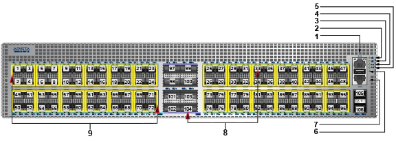
There are twenty four port groups on the DCS-7280CR3-96. Groups are numbered sequentially from Group 1 (ports 1-4). Each group consists of four individual ports as shown (Figure 15).
| 1 | Port groups | 4 | Power supply 1 status LED | 7 | USB port |
| 2 | System status LED | 5 | Power supply 2 status LED | 8 | Ethernet management port |
| 3 | Fan tray status LED6 | 6 | Console serial port | 9 | Port numbers |
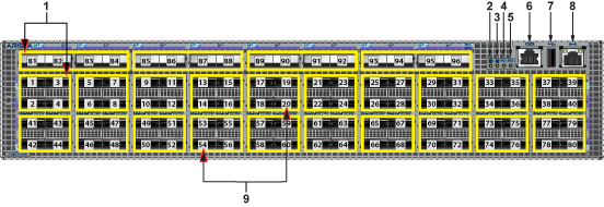
There are twenty four port groups on the DCS-7050SX3-96YC8. Groups are numbered sequentially from Group 1 (ports 1-4). Each group consists of four individual ports as shown (Figure 16).
| 1 | Ethernet management port | 4 | Power supply 1 status LED | 7 | Console serial port |
| 2 | System status LED | 5 | Power supply 2 status LED | 8 | Port numbers |
| 3 | Fan tray status LED | 6 | USB port | 9 | Port groups |