Grounding the Switch
This section discusses the importance of grounding the device to the data center ground.
Normally, the functional grounding of the switch is achieved through the input connection. If you would like to do additional grounding, proceed to the following instructions:
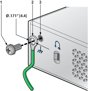
| 1 | Screw M4 (with washer) | 2 | Solder terminal lug | 3 | Grounding point |
Note: Grounding wires and grounding lugs are not supplied with the product. The wire size should meet local and national installation requirements.
CAUTION: The grounding connection must only be removed if all supply connections are disconnected.