7368X Series Maintenance and Field Replacement
Maintenance and Field Replacement
Note Follow ESD protection protocols while handling components of the switch during maintenance operations.
F.1 Switch Card Module
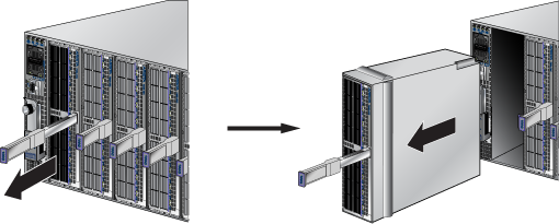
The switch card module is accessible from the rear of the switch as shown in Chapter D. Refer to Figure F-1 for more details on the removal and replacement of the switch card module.
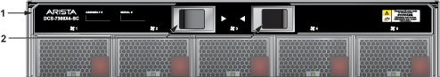
Figure F-1: Switch Card Module Maintenance
|
1
|
Switch Card Release Handle
|
2
|
Switch Card Release Lever
|
The module includes lock-levers that secure it to the chassis. The module and the lock levers are easily damaged by improperly removing, inserting, or handling. Use caution while lifting or moving the module after it is removed from the chassis.
F.1.1 Removing Switch Card Module
Follow the steps listed below to remove the switch card module from the switch chassis.
Step 1 Ground yourself with an ESD wrist strap.
Step 2 Move the release handle down.
Step 3 Pinch the release levers towards the center to unlock the module from the chassis.
Step 4 Carefully, remove the switch card module from the chassis while supporting it through the process.
F.1.2 Inserting Switch Card Module
The module insertion process is the inverse of the removal procedure. Follow the steps listed below to insert the switch card module into a chassis.
Step 1 Align the switch card module with the rails in the chassis for insertion.
Step 2 Slide the module gently into the chassis until you feel a little resistance towards the end. The switch card module will extend just a little bit outside the chassis.
Step 3 Pinch the release levers towards the center and continue to push the module in until it is flush with the chassis and let go of the release levers.
Step 4 Try moving the module out gently, without engaging the release levers. The module will not move if it is seated correctly.
Step 5 Return the release handle to its locked position (up).
Note Descriptions for the removal and replacement of power supplies and fans are for a representative power supply or fan. Locations of status indicator LEDs may differ. Refer to the front and rear panel illustrations of your device to locate the appropriate LED.
F.2 Power Supplies
The power supplies are accessible from the rear of the switch as shown in Chapter D. Refer to Figure F-2 for more details on the removal and replacement of a power supply unit.
The following steps are required when removing power supplies from a switch.
F.2.1 Removing a Power Supply
Step 1 Ground yourself with an ESD wrist strap.
Step 2 Power down the power supply to be removed by disconnecting the AC power cable.
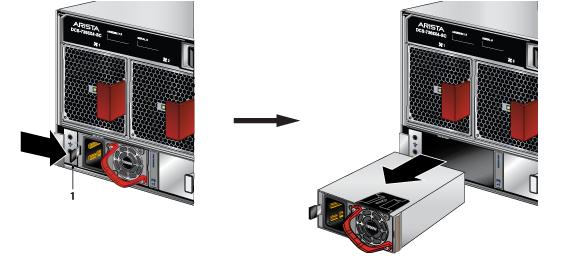
Step 3 Push the power supply release handle and remove the power supply ( Figure F-2).
Figure F-2: Remove power supply
|
1
|
PSU Release Handle
|
|
|
F.2.2 Installing a Power Supply
You must make space for installing the power supply by removing an existing one ( Section F.2.1).
Step 1 Remove the replacement power supply from its packaging.
Step 2 Slide the new power supply into the empty slot.
Step 3 Slide the new power supply into the switch until the power supply is fully seated and the release handle snaps into place.
Step 4 Connect the power cord to the power supply.
Step 5 Verify the LED(s) on the power supply.
Note The Power Supply status LED should be a steady green for normal operation.
Step 6 Verify the new power supply operation by issuing the show environment power command.
switch#show environment power
The output of the command will list the power supplies in operation and should include the one you replaced.
F.3 Fan Modules
The fan modules are accessible from the rear of the switch as shown in Chapter D. Refer to Figure F-3 for more details on the removal and replacement of a fan module.
F.3.1 Removing a Fan Module
The following steps are required when removing or replacing fans from a switch.
Step 1 Ground yourself with an ESD wrist strap.
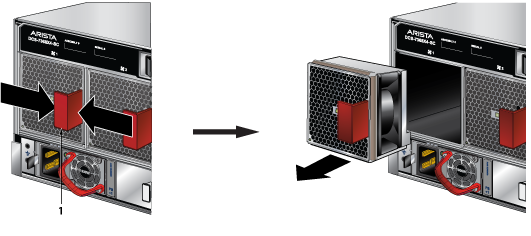
Step 2 Push the fan module release lever and slide the fan module out of the switch ( Figure F-3).
Figure F-3: Removing fan module
|
1
|
Fan Module Release Lever
|
|
|
F.3.2 Installing a Fan Module
You must make space for installing the fan module by removing an existing one ( Section F.3.1).
Step 1 Remove the replacement fan from its packaging.
Step 2 Slide the new fan module into the switch until the module is fully seated and the release lever snaps into place.
The fan installation indicator will be green when the fan is installed and seated correctly.
Step 3 Verify that the fan module is working normally.
Note The fan module status LED should be a steady green for normal operation.
F.4 Supervisor Module
The supervisor module is accessible from the front of the switch as shown in Chapter C. Refer to Figure F-4 for more details on the removal and replacement of a supervisor module.
Note Supervisors are hot-swappable. The switch will reboot when the replacement supervisor powers up.
Figure F-4: Supervisor Module Maintenance
F.4.1 Removing Supervisor Module
Perform the following steps to remove the module.
Step 1 Put on a grounded ESD strap.
Step 2 Lift the supervisor module ejector latch and move the latch down to release the supervisor module.
Step 3 Gently remove the supervisor module by pulling outwards.
F.4.2 Installing Supervisor Module
You must make space for installing the module by removing an existing one ( Removing Supervisor Module). Perform the following steps to install the module.
Step 1 Put on a grounded, anti-static ESD strap.
Step 2 Unpack the supervisor module to be installed.
Step 3 Slide supervisor module into slot.
Step 4 Raise the ejector handle and latch it into place.
Verify that the module is operating normally.
F.5 Linecards
The linecards are accessible from the front of the switch as shown in Chapter C. The linecards are hot-swappable. You must take into account that the linecard you are inserting is compatible with the switch and the linecard that you are replacing. Refer to Figure F-5 for more details on the removal and replacement of a linecard module.
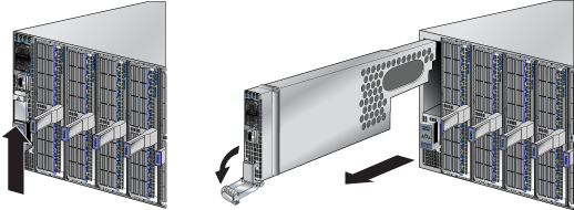
Figure F-5: Linecard Module Maintenance
F.5.1 Removing Linecard
Perform the following steps to remove a linecard.
Step 1 Put on a grounded, anti-static ESD strap.
Step 2 Use the ejector handle or lever in the middle of the linecard to release it from the chassis.
Step 3 Slide the linecard gently out of the slot.
F.5.2 Installing Linecard
You must make space for installing the linecard by removing an existing one ( Removing Linecard) from a linecard slot available on the switch.
Step 1 Put on a grounded, anti-static ESD strap.
Step 2 Unpack the linecard to be installed.
Step 3 Slide the linecard gently into the slot.
Step 4 Use the ejector handle of the linecard to seat the linecard into the chassis.
Step 5 Verify that the linecard is operating normally ( Table A-3).
F.6 Optical Transceivers
For more information about supported optical transceivers and how to remove or install them, refer to Transceiver Guide.