Cabling the Modular Switch
- Cabling the Power Supplies
- Cabling Secondary Ground
- Cabling the AC Power Supply
- Cabling the DC Power Supply
- DC Power Adapter Installation for PWR-2700-DC-R
- Power Supply Specifications
- Power Supply Configurations
- Power Supply Redundancy
- Connecting Supervisor Cables
- Connecting Linecard Modules and Cables
Cabling the Power Supplies
Before you begin, refer to the Arista Networks document Compliance and Safety Guide, available at https://www.arista.com/en/support/product-documentation.
Power down the switch. Remove all power cords from the power inlets.
Mettez le commutateur: Retirez tous les cordons d'alimentation des prises d'alimentation
Installation of this equipment must comply with local and national electrical codes. Consult with the appropriate regulatory agencies and inspection authorities to ensure compliance if necessary.
Installation de cet équipement doit être conformes aux codes électriques locaux et nationaux. Si nécessaire, consulter les organismes de réglementation appropriés et des autorités de contrôle pour assurer la conformité.
Many configurations will require additional power supplies.
Nombreuses configurations exigera des alimentations supplémentaires.
All power supply slots must be filled with either a power supply or blank to ensure proper airflow.
Tous les emplacements d'approvisionnement de puissance doivent être remplis avec une alimentation ou vide pour assurer un débit d'air appropriée.
Read all installation instructions before connecting the system to the power source.
Lire toutes les instructions d'installation avant de brancher le système à la source d'alimentation.
The 7500N chassis requires the connection of at least two operating power supplies in the top row to active circuits.
Each power supply includes a fan that maintains proper power supply temperature and cools the supervisor modules. The appendices display the location of components for all switches described in this guide.
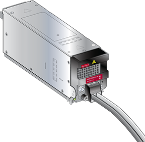
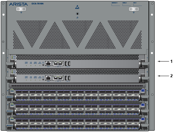
Figure 1 shows the supported power supplies for the 7500N family of switches.
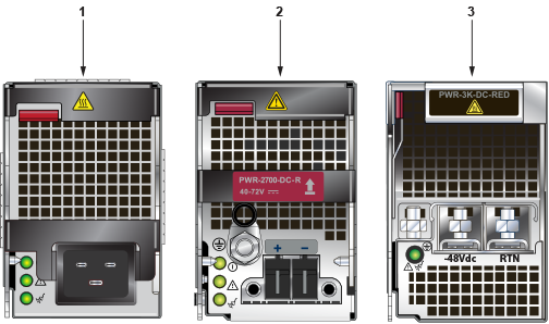
| 1 | PWR-3KT-AC-Red | 2 | PWR-2700-DC-R | 3 | PWR-3K-DC-Red |
Cabling Secondary Ground
The Front Panel displays the secondary grounding pads' location on the switch chassis's front panel. After mounting the switch into the rack, connect at least one of the secondary grounds to the data center ground. After the switch is grounded, ESD wrist straps can be grounded by connecting them to one of the attach points.
Grounding wires and grounding lugs are not supplied. Wire size should meet local and national installation requirements. Commercially available 2 or 4 AWG wire is recommended for installations in the U.S.
À la terre et de mise à la terre fils cosses ne sont pas fournis. Calibre des fils doit satisfaire des exigences de l'installation locale et nationale. Disponible dans le commerce 2 ou 4 AWG fil est recommandé pour les installations aux États-Unis.
This equipment must be grounded. Never defeat the ground conductor. This unit requires over-current protection.
Cet équipement doit être mis à la terre. Ne jamais modifier le conducteur de terre. Cet appareil nécessite de protection contre les surintensités.
Secondary Grounding wires, lugs, and screws (M4 x 0.7) are not supplied.
Secondaire à la terre, câbles, cosses et vis (M4 x 0.7) ne sont pas fournis.
Secondary ground locations on the switches are displayed in the Rear Panel.
Turn off the switch: Remove all power cords from the power inlets.
Cabling the AC Power Supply
The Rear Panel displays the rear panel location of power supplies and fabric modules.
The switch uses power cables with IEC-320 C-19 plugs. The accessory kit provides IEC-320 C-19 to C-20 power cables, each two meters long. To insert a power cable, plug the power cables into the inlet.
Cabling the DC Power Supply
The -48V and Battery-Return leads are a pair and should run adjacent and be approximately the same length.
Le - 48V et câbles de batterie-retour sont une paire courir à côté de l'autre et doivent être à peu près la même longueur.
DC Power Supplies
Wire and Lug Preparation
Before installing, remove power from DC circuits by turning off the power line servicing the circuits. Prepare the stranded wiring before you begin a DC power installation.
- Stranded copper wiring is required.
- Commercially available 2 to 4 AWG wire is recommended for installations in the U.S.
- Wire size should meet local and national installation requirements.
- Grounding wires and grounding lugs are not supplied.
- Strip the wires to the appropriate length for the lugs.
- Wire size should meet local and national installation requirements.
The wires connecting the DC power supply to the power source must meet the following requirements:
- DC Input Wire Size: 2 – 4 AWG (33.6 mm2 to 21.2 mm2).
- Primary Ground Wire Size: 2 – 4 AWG (33.6 mm2 to 21.2 mm2) per power supply.
- The conductors are copper.
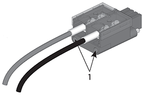
Figure 2. Lugs Wiring Terminations 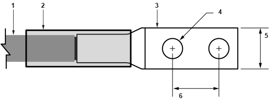
1 Insulated wire 3 -48V + RTN lug 5 1/2” 2 Heat-shrink tubing 4 1/4” 6 5/8” -
Figure 3. Ground Lug Wiring Termination (PWR-2700W-DC-R) 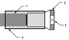
1 Insulated wire 3 5/16” Ø 2 Ground lug (right angle) 4 Heat-shrink tubing
- The conductors are copper.
- Primary Ground Wire Size: 2 – 4 AWG (33.6 mm2 to 21.2 mm2) per power supply.
- Commercially available 2 to 4 AWG wire is recommended for installations in the U.S.
PWR-3K-DC-RED Power Supply
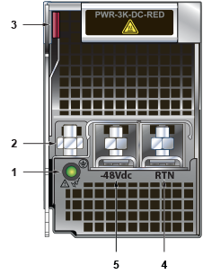
| 1 | Status LED | 3 | Ejector | 5 | -48V terminal |
| 2 | Ground terminal | 4 | RTN terminal |
- Prepare the stranded wiring; see Wire and Lug Preparation.
- Attach the power cable to the supply terminals.
- Tightening Torque: 2.7 N-m (24 in.-lbs.)
DC Power Adapter Installation for PWR-2700-DC-R
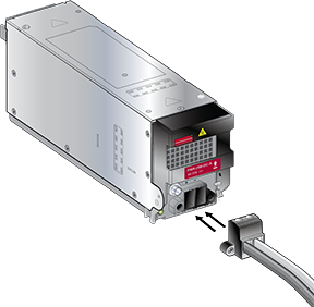
Connecting the Ground to PWR-2700-DC-R Power Supply
The Figure 5 displays the PWR-2700-DC-R power supply without the DC adapter.
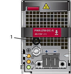
| 1 | Ground |
Connecting the Power Cable Lug to the Terminal Studs
- Remove the clear plastic cover protecting the terminal studs on the adapter by lifting the small center tab while sliding the cover off the adapter.
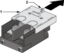
1 Plastic lid 2 Center tab - Remove the flange locking nuts from each of the terminal studs.
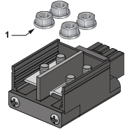
1 Flange locking nuts - Secure each power cable lug to the terminal studs with the flange locking nuts.
- Attach the positive (+) DC source power cable lug to the RTN (return) terminal.
- Attach the negative (–) DC source power cable lug to the –48V (input) terminal.
- Torque the four flange locking nuts to 2.7 N-m (24 in.-lbs.).
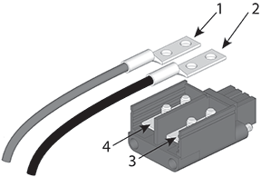
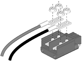
1 Compression lugs 3 -48V 2 Compression lugs 4 RTN
- Slide the cover over the terminal studs until it clicks into place.
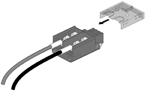
1 Captive screw slots - Insert the adapter into the DC power supply.
Power Supply Specifications
The Table 1 table shows the power supply specifications for each of the PSUs supported.
| Power Supply | Maximum Output Power Rating (DC) | Input Voltage and Frequency | Maximum Input Current | Input Branch Circuit Protection |
|---|---|---|---|---|
| PWR-2700-DC-R | 2600 W | -48 or -60 V (nominal) | 80 A | 100 A |
| PWR-3K-DC-RED | 3000 W | -48 or -60 V (nominal) | 80 A | 100 A |
| PWR-3KT-AC RED | 3000 W | 200 to 240 V (nominal) 50 - 60 Hz (nominal) | 16 A | 20 A |
Power Supply Configurations
The Table 2 table shows the power supply configurations for the modular switches.
| Modular Switch | Recommended Number of PSUs (for redundancy) | Number of PSUs Shipped in Bundle | Minimum Number of PSUs Required (per power domain) | Maximum Number of PSUs Supported | Number of Power Domains |
|---|---|---|---|---|---|
| DCS-7504N | 4 | 4 | 2 | 4 | 1 |
| DCS-7508N | 6 | 6 | 2 | 8 | 1 |
| DCS-7512N | 8 | 8 | 2 | 12 | 1 |
| DCS-7516N | 12 | 12 | 3 | 20 | 2 |
Recommendations for Power Supply Usage
- Use a separate circuit with the required protection for each power supply.
- Use the same PSU model when replacing a failed PSU. Check for a suitable alternative if the model is no longer supported or available.
- Do not mix power supply types unless your switch allows for mixing power supplies.
- You must populate each power domain with the minimum number of PSUs required. Domains are separate banks of grouped supplies, Ten high and ten low for the 160-slot chassis (Domain 1: PS1 – PS10; Domain 2: PS11 – PS20).
- Chassis with multiple power domains should have equal supplies in each domain.
- For supervisor cooling purposes, all systems require the minimum number of PSUs in the top section behind the supervisors, as specified in the Power Supply Configurations.
- For 8-slot and 12-slot chassis (grouped power supplies top and bottom), Arista recommends an equal number of power supplies in the top and bottom groups.
- For the 16-slot chassis with two power domains, the power domain with the lowest number of power supplies prescribes the total power available. Therefore, Arista recommends an equal number of PSUs in each domain.
- Valid redundancy configurations for each domain are described in the Power Supply Redundancy section.
Power Supply Redundancy
Installation of this equipment must comply with local and national electrical codes. Consult with the appropriate regulatory agencies and inspection authorities to ensure compliance if necessary.
Installation de cet équipement doit être conformes aux codes électriques locaux et nationaux. Si nécessaire, consulter les organismes de réglementation appropriés et des autorités de contrôle pour assurer la conformité.
Read all installation instructions before connecting the system to the power source.
Lire toutes les instructions d'installation avant de brancher le système à la source d'alimentation.
Most installations will have redundant, dual, independent power feeds.
- Each supply is wired to one feed, either A or B.
- The recommended installation is to alternate A B feeds. You would wire ABAB from left to right in a four-supply system configuration.
- All power supply slots must be filled with a powered supply (A or B), a blank (X), or a non-powered power supply.
For supervisor cooling purposes, all systems require a minimum number of operating power supplies (see Power Supply Configurations) at all times in the top half of the chassis. For optimal performance, alternate pairs of power supplies (A and B) evenly from top to bottom (8 or more slot chassis).
- AXAX Minimum Configuration supported, 2+0 (non-redundant)
- ABAB 2+2 redundant
- ABAB (Upper), AB (Lower) 3+3 redundancy
- ABAB (Upper), ABAB (Lower) 4+4 redundancy
- ABXXAB (Upper), ABXXAB (Lower) 4+4 redundancy (12-slot chassis)
- ABABAB (Upper), ABABAB (Lower) 6+6 redundancy
- AAAX for 3+0 or 2+1 redundancy, with the X anywhere
- AAAA for 4+0 or 3+1 redundancy
- ABABAB (Upper), ABABAB (Lower) 6+6 redundancy (12-Slot Chassis)
- XABAX/XBABX (Upper), XABAX/XBABX (Lower) 6+6 redundancy (16-slot chassis)
- BABAB/ABABA (Upper), BABAB/ABABA (Lower) 10+10 redundancy (16-slot chassis)
Each power supply includes a fan that maintains proper power supply temperature and cools the supervisor modules. The appendices display the location of the components on all switches described in this guide.
The Front Panel displays the front panel location of the supervisor modules.
The Rear Panel displays the rear panel location of power supplies and fabric modules.
This unit requires over-current protection.
Cet appareil nécessite de protection contre les surintensités.
Unused slots must be occupied or covered with a blank to ensure proper airflow through the chassis.
Les emplacements inutilisés doivent être occupés ou recouvert d'un blanc pour assurer la bonne circulation d'air dans le châssis.
Connecting Supervisor Cables
Supervisor modules contain console, management, and USB ports. Figure 6 and Figure 7 display port locations on the supervisors.
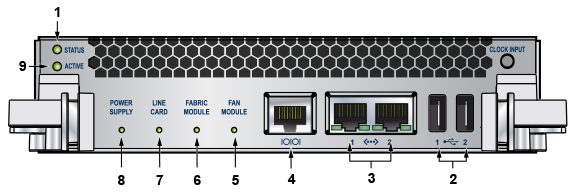
| 1 | Status LED | 5 | Fan module status LED | 9 | Active LED |
| 2 | USB ports | 6 | Fabric module status LED | ||
| 3 | Ethernet management ports | 7 | Linecard status LED | ||
| 4 | Serial console port | 8 | Power supply status LED |
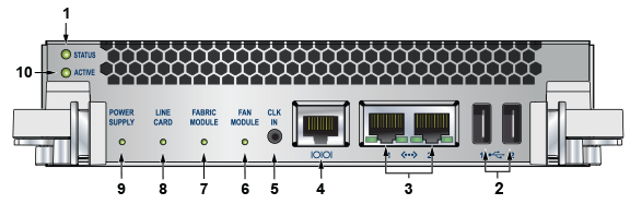
| 1 | Status LED | 5 | Clock input port (optional) | 9 | Power supply status LED |
| 2 | USB ports | 6 | Fan module status LED | 10 | Active LED |
| 3 | Ethernet management ports | 7 | Fabric module status LED | ||
| 4 | Serial console port | 8 | Linecard status LED |
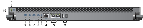
| 1 | Status LED | 5 | Clock input port (optional) | 9 | Power supply status LED |
| 2 | USB ports | 6 | Fan module status LED | 10 | Active LED |
| 3 | Ethernet management ports | 7 | Fabric module status LED | ||
| 4 | Serial console port | 8 | Linecard status LED |
- Console (Serial) Port: Connect to a PC with RJ-45 to DB-9 serial adapter cable. Default switch settings include:
- 9600 baud
- No flow control
- 1 stop bit
- No parity bits
- 8 data bits
The DCS-7516-SUP supervisor cards must be installed in one of the two designated slots in the DCS-7516N switch, as shown in Figure 9.
| 1 | Supervisor slot 1 |
| 2 | Supervisor slot 2 |
| RJ-45 | DB-9 | RJ-45 | DB-9 | |||||
|---|---|---|---|---|---|---|---|---|
| RTS | 1 | 8 | CTS | GND | 5 | 5 | GND | |
| DTR | 2 | 6 | DSR | RXD | 6 | 3 | TXD | |
| TXD | 3 | 2 | RXD | DSR | 8 | 4 | DTR | |
| GND | 4 | 5 | GND | CTS | 8 | 7 | RTS | |
- Ethernet management port: Connect to 10/100/1000 management network with a RJ-45 cable.
- Connect to 10/100/1000 management network with a RJ-45 cable.
- USB Port: This may be used for software or configuration updates.
- Clock Input Port: The port type is MCX connector, 2-5.5V, 50 ohm termination.
Connecting Linecard Modules and Cables
Install required SFP, SFP+, QSFP+, QSFP100, and CFP2 optic modules in linecard module ports (Figure 10).
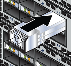
Connect cables as required to linecard module ports or fixed MPO ports. Supervisor and linecard module ejectors on the front of the chassis assist with cable management.
Excessive bending can damage interface cables, especially optical cables.
Flexion excessive peut endommager les câbles d'interface, en particulier les câbles optiques.