Preparation
The following topics are covered in this section:
Site Selection
The following criteria should be considered when selecting a site to install the switch:
- Floor Space: Install the switch in an area that provides adequate clearance for removing front and rear components.
The Figure 1 displays the dimensions and footprint of the switch clearance requirements for the switches.

The Table 1 shows the dimensions for each of the modular switches.
| Switch | Clearance Requirements Dimensions | ||
|---|---|---|---|
| A | B | C | |
| DCS-7804 | 38.4 cm (15.1 in.) | 102.1 cm (40.2 in.) | 58.9 cm (23.2 in.) |
| DCS-7808 | 38.4 cm (15.1 in.) | 102.1 cm (40.2 in.) | 58.9 cm (23.2 in.) |
| DCS-7812 | 38.4 cm (15.1 in.) | 102.1 cm (40.2 in.) | 58.9 cm (23.2 in.) |
| DCS-7816 | 38.4 cm (15.1 in.) | 102.1 cm (40.2 in.) | 58.9 cm (23.2 in.) |
- Temperature and Ventilation: For proper ventilation, install the switch where there is ample airflow to the front and back of the switch. The temperature should not go below 0° or exceed 40°C.
Important: To prevent the switch from overheating, do not operate it in an area where the ambient temperature exceeds 40°C (104°F).
Pour empêcher l'interrupteur de surchauffe, ne pas utiliser il dans une zone où la température ambiante est supérieure à 40°C (104°F).
- Airflow Orientation: The fans direct air from the front panel to the rear panel. Orient the front panel toward the cool aisle.
- Rack Space Requirements: The Table 2 shows the rack space requirements for each of the modular switches.
Table 2. Rack Space Requirements Switch Rack or Cabinet (standard 19" EIA) 2-Post 4-Post Switch Height (RU) DCS-7804 No Yes 10 DCS-7808 No Yes 16 DCS-7812 No Yes 23 DCS-7816 No Yes 32 Note: The accessory kit provides the required mounting hardware for each switch. - Power Requirements: Arista switches require a minimum number of operating power supplies in all chassis, AC or DC, and for each power domain of switches with multiple power domains. Refer to Cabling the Power Supplies for more details regarding your switch.
Important: DC cables should be protected with circuit over-current protection devices and circuit disconnect means. To power off a unit, power must be disconnected from ALL power cables.
DC câbles doivent être protégés avec dispositifs de protection de surintensité circuit et moyens de déconnexion du circuit. Pour éteindre une unité, l'alimentation doit être débranchée de TOUS les câbles d'alimentation.
- Other Requirements: Select a site where liquids or objects cannot fall onto the equipment and foreign objects are not drawn into the ventilation holes. Ensure these guidelines are met:
- Clearance areas to the front and rear panels allow for unrestricted cabling.
- All front and rear panel indicators can be easily read.
- AC power cords can reach from the AC power outlet to the input connectors.
- DC power cables can reach from the DC power distribution unit to the input connectors.
Tools and Parts Required for Installation
The following tools are required to install a modular switch:
- Mechanical device capable of lifting chassis being installed (Table 1).
- Torque reading nut driver (for DC power supplies)
- #2 Phillips head screwdriver
Rack Mount
The Table 3 shows the rack components required for each of the modular switches.
| Switch | Rack or Cabinet (standard 19" EIA) | ||
|---|---|---|---|
| Rack Screws (1) | Rack Nuts (2) | Notes | |
| DCS-7804 | 21(3) | 21(3) | 4-post installation |
| DCS-7808 | 21(3) | 21(3) | 4-post installation |
| DCS-7812 | 27(3) | 27(3) | 4-post installation |
| DCS-7816 | 35(3) | 35(3) | 4-post installation |
1The accessory kit includes screws that fit many common equipment racks.
2Rack nuts are only for racks with unthreaded, rack-post holes.
3These are in addition to the rack-mount kit screws required for the cradle.
Unpacking and Moving the Switch
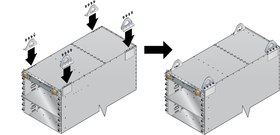
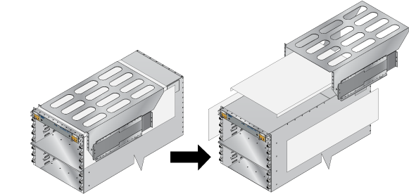
The DCS-7816 accessory kit includes bolts and lifting brackets (Figure 2) that must be attached to the top of the chassis with the bolts supplied for lifting the chassis from the pallet onto the transport lift. You can use any appropriate lifting mechanism/tool to unload the switch. A platform lift is recommended for transportation and installation of the switch. The rack mounting cradle is shipped nested upside down over the top of the chassis for all switches (Figure 3). There is a protective film on the top and sides to keep the cradle from scratching the chassis during transport.
Unpacking and Moving the Switch (Example)
- 1000 lb lifting straps
- Server Lift SL-1000X® Super-Duty Lift
- 1000 lb capacity
- Battery operated and motorized
- Integrated rollers with lockout
- Server Lift SL-1000X® Super-Duty Lift
The DCS-7816 chassis ships on an engineered pallet as shown below.
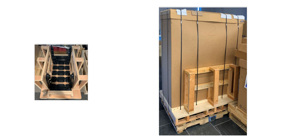
- Cut away the straps and remove the cardboard to expose the chassis with the rack kit basket attached and nested on top of the chassis.
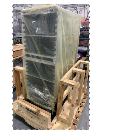
- From the accessory kit shipped with the chassis, remove and attach the lifting brackets to the top of the chassis.
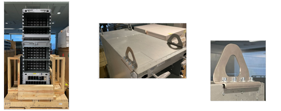
- Attach the 1000 lb lifting straps to the lifting brackets on the chassis, and the loops through the prongs of the lift.

- Place the chassis on the transport lift (Server Lift SL-1000X® Super-Duty Lift) with the lift platen in the neutral position and the chassis aligned for moving into the rack.
Note: Populate the chassis with line-cards and fabric modules only after insertion into the rack.
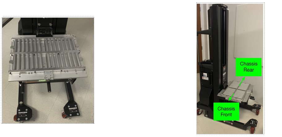
- Align and move the chassis into the rack using the translatable platen.
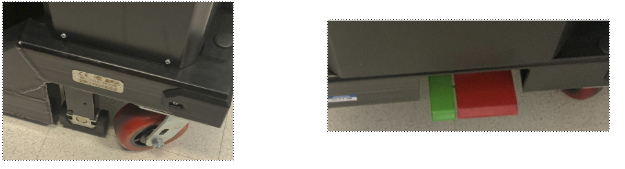
Note: Use the built-in, foot-pedal actuated lock to secure lift while sliding the chassis into rack.
Note: Before moving the chassis into the rack, you must attach the cradle to the rack (DCS-7804, DCS-7808, DCS-7812, and DCS-7816 Rack Mounting).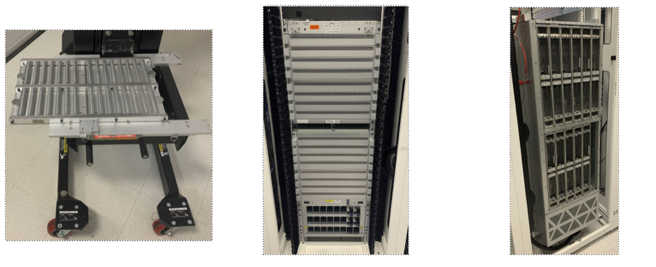
Electrostatic Discharge (ESD) Precautions
Observe these guidelines to avoid ESD damage when installing or servicing the switch.
- Assemble or disassemble equipment only in a static-free work area.
- Use a conductive work surfaces (such as an anti-static mat) to dissipate static charge.
- Wear an ESD wrist strap to dissipate static charge accumulation.
- Minimize handling of assemblies and components.
- Keep replacement parts in their original static-free packaging.
- Remove all plastic, foam, vinyl, paper, and other static-generating materials from the work area.
- Use tools that do not create ESD.