Rear Panel Features and Indicators
This section displays the rear panel of the CloudVision AGNI Appliance.
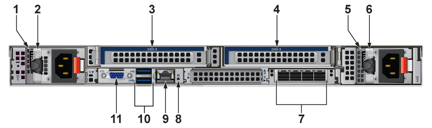
| Number | Indicator, Button, or Connector | Description |
|---|---|---|
| 1 | PSU 1 Release Latch | Release latch/handle used to unlock and hot-swap Power Supply Unit 1 (PSU1). |
| 2 | PSU 1 status LED | LED indicator showing the power state, health, and fault status of PSU1. |
| 3 | PCIe Expansion Slot 1 (Gen 5) | Expansion card riser slot supporting high-speed PCIe Gen 5 add-in cards (e.g., RAID controllers, NICs, accelerator cards). |
| 4 | PCIe Expansion Slot 2 (Gen 5) | Secondary expansion card riser slot supporting high-speed PCIe Gen 5 add-in cards. |
| 5 | PSU 2 Release Latch | Release latch/handle used to unlock and hot-swap Power Supply Unit 2 (PSU2). |
| 6 | PSU 2 status LED | LED indicator showing the power state, health, and fault status of PSU2. |
| 7 | Ethernet Connectors | Unused |
| 8 | System identification button and Indicator | The identification buttons on the front and back panels can be used to locate a particular system within a rack. When one of these buttons is pressed, the system status indicator on the back flashes until one of the buttons is pressed again.
Press to toggle the system ID on and off. If the system stops responding during POST, press and hold the system ID button for over five seconds to enter BIOS progress mode. To reset the iDRAC (if not disabled in the F2 iDRAC setup), press and hold the button for over 15 seconds. |
| 9 | iDRAC port | Dedicated management port for the iDRAC port card.
Enables you to remotely access iDRAC. when the front iDRAC port is connected with the network, the rear iDRAC port is auto disabled. |
| 10 | USB connector | Allows you to connect USB devices to the system. The port is USB 3.0-compliant. |
| 11 | Video connector | Allows you to connect a VGA display to the system. |