Taiwan RoHS Information
This section provides the Taiwan RoHS information for switches this guide covers.
For the Taiwan BSMI RoHS Table, go to https://www.arista.com/assets/data/pdf/AristaBSMIRoHS.pdf.
This section provides the Taiwan RoHS information for switches this guide covers.
For the Taiwan BSMI RoHS Table, go to https://www.arista.com/assets/data/pdf/AristaBSMIRoHS.pdf.
This section lists the Regulatory Model Numbers (RMNs) for the product models for the switches described in this document.
| Regulatory Model Number (RMN) | Product Name(s) |
|---|---|
| AN1733 | CCS-720XP-96ZC
CCS-720XP-96ZC2-M-S |
This section displays the rear panel of all switches this guide covers. Depending on the power supply modules installed, the rear panel on your switch may differ slightly.
%20Modules.png)
| 1 | Fan Module 1 | 4 | Power Supply Module 1 | 7 | Power Supply Module 4 |
| 2 | Fan Module 2 | 5 | Power Supply Module 3 | ||
| 3 | Fan Module 3 | 6 | Power Supply Module 2 |
This section displays the front panel of all switches covered by this guide.
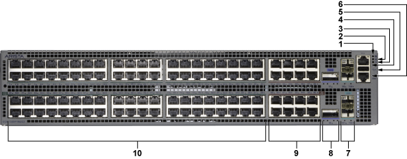
| 1 | System status LED | 5 | USB port | 9 | 5G PoE ports |
| 2 | Fan status LED | 6 | Console serial port | 10 | 2.5G PoE ports |
| 3 | PSU status LED | 7 | 25G ports | ||
| 4 | Ethernet management port | 8 | 100G ports |
| 1 | System status LED | 5 | USB port | 9 | 5G PoE ports |
| 2 | Fan status LED | 6 | Console serial port | 10 | 2.5G PoE ports |
| 3 | PSU status LED | 7 | 25G ports | ||
| 4 | Ethernet management port | 8 | 100G ports |
Each switch provides an accessory kit containing the parts required to install the switch. This section lists the installation parts contained in the switch accessory kit.
This section discusses the following topics:
Two-post rack mount parts are provided in the accessory kit.
List of provided cables.
| Quantity | Description |
|---|---|
| 2 | Power cables: IEC-320/C15-C16, 13 A, 250 V, 2-meter |
| 1 | RJ-45 Patch Panel Cable, 2-meter |
| 1 | RJ-45 to DB9 Adapter Cable, 2-meter |
All provided power cables are for use only with Arista products.

This section discusses the following topics:
The system and port status LED indicators are located on the front of the switches.
This section discusses the following topics:
The front panel LEDs on the chassis's right side display the system, fan, and power supply status. The Front Panel displays the front panels of all switches covered by this guide.
The System Status Indicators image displays the CCS-720XP-96ZC2 front panel LEDs.
| 1 | System status LED | 2 | Fan status LED | 3 | PSU status LED |
| LED Name | LED State | Device Status |
|---|---|---|
| System Status | Blinking Green | System powering up. |
| Green | All power supplies and fans are operating normally. | |
| Blue | The locator function is active. | |
| Red | A power supply or fan is missing or in a failed state. | |
| Fan Status | Green | All fans are operating normally. |
| Red | One or more fans have yet to be inserted or have failed. | |
| Power Supply Status | Off | The power supply is not inserted or powered. |
| Green | The power supply is operating normally. | |
| Red | The power supply has failed. |
Port LEDs near their corresponding ports provide a link and operational status. The Port LED image displays the Port LED location on the CCS-720XP-96ZC2 switch. The Front Panel displays the port LED locations of all switches this guide covers.
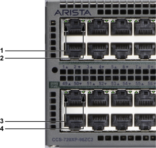
| 1 | Port status LED (upper port) | 3 | Port status LED (upper port) |
| 2 | Port status LED (lower port) | 4 | Port status LED (lower port) |
Port LED States provide status conditions that correspond to port LED states. Port LED behavior for QSFP+ and SFP+ ports is consistent.
| LED State | Status |
|---|---|
| Off | The port link is down. |
| Green | The port link is up. |
| Yellow | The port is software disabled. |
| Flashing Yellow | The port failed diagnostics. |
Fan and power supply modules are accessed from the rear panel. Each fan and power supply module contains an LED that reports the module status. Rear Panel displays the rear panel of all switches covered by this guide.
Fan Status LEDs are on the fan modules, as displayed in Fan Status LED.
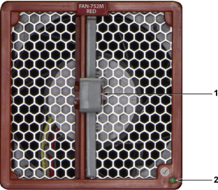
| 1 | Release | 2 | Fan module status LED |
The module installation indicator is green when the fan module is properly installed or red when the module is not fully installed. Fan Status LED States provide status conditions that correspond to fan status LED states.
| LED State | Status |
|---|---|
| Off | The fan module is inserted but not receiving power – it may not be properly seated. |
| Green | The fan is operating normally. |
| Red | The fan has failed. |
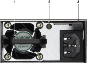
The power supply status LEDs are on the modules, as shown in the AC Power Supply Status LED.
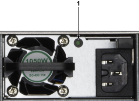
| 1 | PSU module status LED |
The AC Power Supply Status LED States provides conditions corresponding to power supply status LED states.
| Power Supply State | PWR-1021-AC-RED |
|---|---|
| Input power present Normal operation | Green |
| Input power present Power Supply fault | ON/OFF: ON when PSU output is ON, OFF when PSU Output is OFF |
| Input power present Power Supply FAN fault | FLASH 800 ms ON / 800 ms OFF |
| No Input power Supply installed in chassis | OFF |
| Input power present Supply not installed in chassis | Green |
Arista switches ship from the factory in Zero Touch Provisioning (ZTP) mode.
ZTP configures the switch without user intervention by downloading a startup configuration file or a boot script from a location specified by a DHCP server. To manually configure a switch, ZTP is bypassed. The initial configuration provides one username (admin) that is accessible only through the console port because it has no password.
When bypassing ZTP, initial switch access requires logging in as admin, with no password, through the console port. Then, you can configure an admin password and other password-protected usernames.
This manual configuration procedure cancels ZTP mode, logs into the switch, assigns a password to the admin, assigns an IP address to the management port, and defines a default route to a network gateway.
This section discusses the following topics:
After mounting the switch into the rack, connect the switch to the data center ground.
Grounding wires and grounding lugs (M4 x 0.7) are not supplied. Wire size should meet local and national installation requirements. Commercially available 6 AWG wire is recommended for installations in the U.S.
À la terre et de mise à la terre fils cosses (M4 x 0.7) ne sont pas fournis. Calibre des fils doit satisfaire des exigences de l’installation locale et nationale. Disponible dans le commerce 6 fils AWG est recommandé pour les installations aux États-Unis.
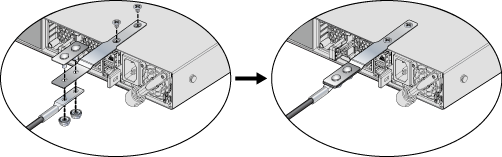
For models that do not have grounding pads, use an adapter as shown for the DCS-7050SX3-96YC8 (Figure 1 - Earth Grounding Adapter for Models such as DCS-7050SX3-96YC8). Assemble an adapter to attach to the chassis (Grounding Adapter Assembly). Once the grounding lug is attached to the adapter, attach it to the chassis.
The following are directions for connecting the power cables.
Installation of this equipment must comply with local and national electrical codes. Consult with the appropriate regulatory agencies and inspection authorities to assure compliance if necessary.
Read all installation instructions before connecting the system to the power source.
This equipment must be grounded. Never defeat the ground conductor.
This unit requires overcurrent protection.
Installation de cet équipement doit être conformes aux codes électriques locaux et nationaux. Si nécessaire, consulter les organismes de réglementation appropriés et des autorités de contrôle pour assurer la conformité.
Lire toutes les instructions d'installation avant de brancher le système à la source d'alimentation.
Cet équipement doit être mis à la terre. Ne jamais modifier le conducteur de terre.
Cet appareil requiert une protection contre les surintensités.
The following AC power supply is supported. Up to four power supplies can power the switch.
PWR-1021-AC-RED
Power requirements vary by switch. Refer to Table 4 - Switch Specifications (Power Draw) for information regarding your specific system. Connect each AC power supply to a circuit that provides the required power.
The Rear Panel displays the location of the power supplies on the switch's rear panel.
Remove all power cords and wires from the power supplies to turn off the switch.
Input power and power supply redundancy depend on the actual system power draw.
Connect each power supply to its input overcurrent protection for maximum Input Power redundancy.
For power supply redundancy, at least one more power supply should be installed than is required to power the system. The Switch Specifications (Power Draw) display the AC power supply.
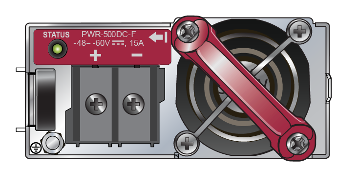
|
1 |
PSU handle |
2 | PSU status LED | 3 | Release |
The accessory kit provides IEC-320 C15 to C16 power cables.
The following DC power supplies are supported.
PWR-521-DC-RED
A disconnect device must be provided as part of the installation.
Ensure power is removed from DC circuits before performing any installation actions. Locate the disconnect device, circuit breakers or fuses on DC power lines servicing the circuits. Turn off the power line circuits or remove the fuses.
Wire size must comply with local and national requirements and electrical codes. Use only copper wire.
Apply ground connection to the switch first during installation and remove last when removing power.
Un dispositif de sectionnement doit être fourni dans le cadre de l'installation.
Pouvoir assurer qu'il est retiré de circuits DC avant d'effectuer des actions d'installation . Localiser les disjoncteurs ou des fusibles sur les lignes de courant continu desservant les circuits. Coupez les circuits de lignes d'alimentation ou retirer les fusibles.
Le calibre du fil doit être conforme aux exigences locales et nationales et les codes électriques. Utiliser du fil de cuivre.
Appliquer connexion à la terre à l'interrupteur premier lors de l'installation et de supprimer la dernière alimentation lors du débranchement.
Before performing any installation actions, ensure power is removed from DC circuits by turning off the power line servicing the circuits. Prepare the stranded wiring before you begin a DC power installation.
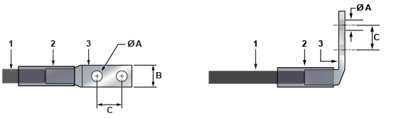
| 1 | Insulated wire | 3 | Lug (all three terminals) | B | 1/2" |
| 2 | Heat-shrink tubing | A | 1/4" | C | 5/8" |
To connect a DC power supply to power source:
The accessory kit includes the following cables:
The following RJ-45 to DB-9 Connections table lists the pin connections of the RJ-45 to DB-9 adapter cable.
| RJ-45 | DB-9 | RJ-45 | DB-9 | ||||
|---|---|---|---|---|---|---|---|
| RTS | 1 | 8 | CTS | GND | 5 | 5 | GND |
| DTR | 2 | 6 | DSR | RXD | 6 | 3 | TXD |
| TXD | 3 | 2 | RXD | DSR | 7 | 4 | DTR |
| GND | 4 | 5 | GND | CTS | 8 | 7 | RTS |
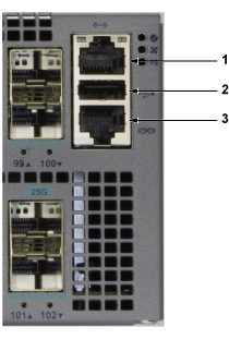
|
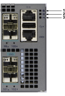
1 |
Ethernet management port |
2 | USB port | 3 | Console serial port |
Connect the front panel ports as follows:
Console (Serial) Port: Connect to a PC with the RJ-45 to DB-9 serial adapter cable. The switch uses the following default settings:
Excessive bending can damage interface cables, especially optical cables.
Flexion excessive peut endommager les câbles d'interface, notamment des câbles optiques.
This section discusses the following topics:
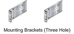
To mount the switch onto a two-post rack, assemble the mounting brackets to the chassis, then attach the brackets to the rack posts. Two-post accessory kits include two three-hole mounting brackets.
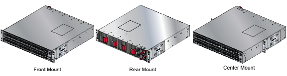
Each chassis side has attachment pins that align with bracket holes; the number of pins (six or seven) varies by switch model. Pin orientation is symmetric and equidistant, with supporting bracket placement where the flange is either flush with the front and rear panels or not flush with the panels. Each bracket hole includes a key opening for placing the bracket flush with the chassis and then locking it into place.
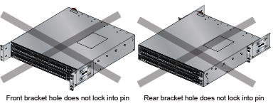
Attachment pins must engage all three upper bracket holes.
Goupilles de fixation doivent s’engager tous les trois trous de la bride supérieure.
Figure 1 - Bracket Mount Examples for Two-Post Rack Mount displays proper bracket mount configuration examples. Figure 2 - Improper Bracket Mount Examples for Two-Post Rack Mount displays improper bracket mount configuration examples.
This procedure attaches mounting brackets to the switch chassis (Figure 3 - Attaching the Mounting Brackets to the Switch Chassis).
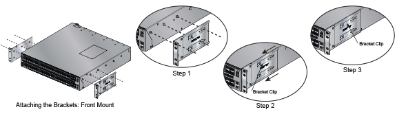
To remove the mounting bracket from the chassis, lift the front edge of the mounting bracket clip with a flathead screwdriver and slide the bracket away from the front flange (opposite from the installation direction).
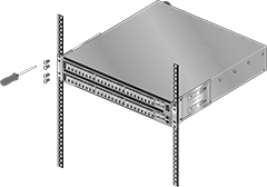
This procedure attaches the switch to the rack.
This section discusses the following topics:
Consider the following criteria when selecting a site to install the switch:
Temperature and Ventilation:For proper ventilation, install the switch with ample airflow to the front and back of the switch. The ambient temperature should not go below 0° or exceed 40°C
To prevent the switch from overheating, do not operate it in an area where the ambient temperature exceeds 40°C (104°F).
Pour empêcher l'interrupteur de surchauffe, ne pas utiliser il dans une zone où la température ambiante est supérieure à 40°C (104°F).
When mounting the switch in a partially filled rack, load the rack from bottom to top, with the heaviest equipment at the bottom. Load the switch at the bottom if it is the only item in the rack.
Two circuits provide redundancy protection. Connecting Power Cables describes power cable requirements.
The power input plug-socket combination must be accessible at all times; it provides the primary method of disconnecting power from the system.
La combinaison de la puissance-prise d'entrée doit être accessible en tout temps ; Il fournit le principal moyen de coupure d'alimentation du système.
Remove all power connections to de-energize the unit.
Toutes les connexions d'alimentation doivent être enlevées pour hors tension l'appareil.
This unit is intended for installation in restricted access areas.
Cet appareil est prévu pour une installation dans les zones d'accès restreintes.
The following tools and equipment are required to install the switch:
The accessory kit does not include screws for attaching the switch to the equipment rack. When installing the switch into an equipment rack with unthreaded post holes, nuts are also required to secure the switch to the rack posts.
Observe these guidelines to avoid ESD damage when installing or servicing the switch.