Configure Edges with New Orchestrator UI
You can configure the Edges using the Orchestrator UI. To configure a specific Edge:
- In the Enterprise portal, click .
- The Edges page displays the existing Edges.
- Click the link to an Edge or click the View link in the Device column of the Edge.
- The configuration options for the selected Edge are displayed in the Device tab.
Figure 1. Configuring Edges 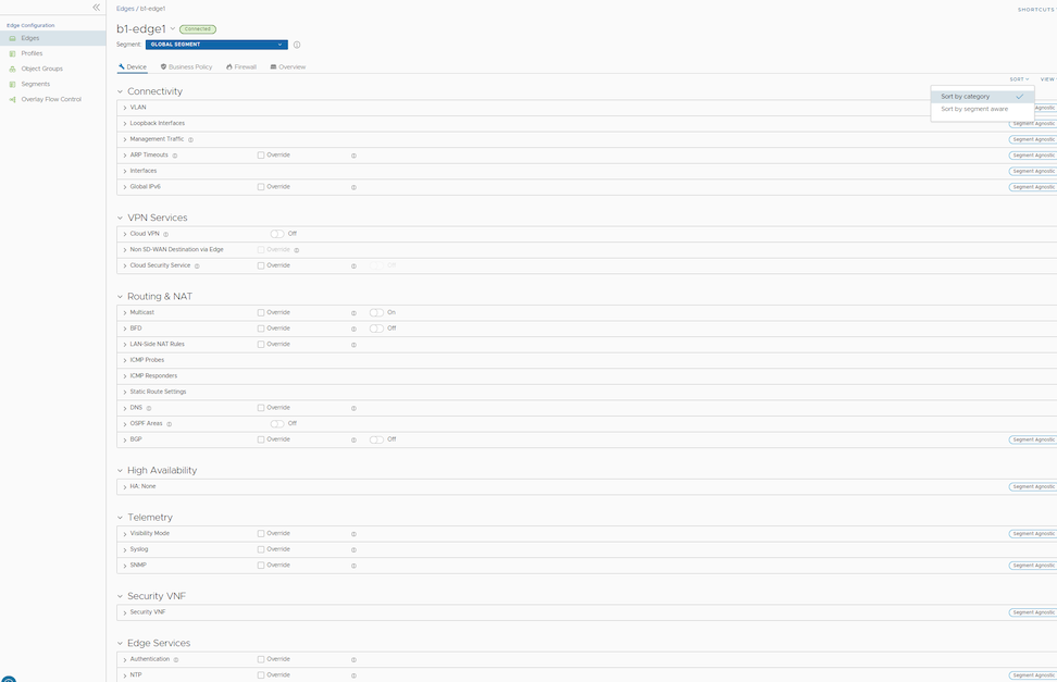
- Click View to expand or collapse the view of available settings.
- You can also view the configuration settings sorted by category or segmentation. By default, the settings are sorted by category. If you choose to sort by segmentation, the settings are grouped as segment aware and segment agnostic.
- For some of the settings, the configuration is inherited from the associated Profile. To edit inherited configuration for the Edge, select the Override checkbox.
The following settings are available when you choose to sort by category:
Table 1. Connectivity Settings Settings Description VLAN Configure the VLANs with both IPv4 and IPv6 addresses for Edges. Click the IPv4 or IPv6 tabs to configure the corresponding IP addresses for the VLANs. For more information, see Configure VLAN for Edges. Note: When you create a new VLAN or edit a VLAN configuration using the new Orchestrator UI, the VLAN appears as read-only in the classic Orchestrator UI. After creating or editing a VLAN with new Orchestrator UI, you can modify the settings of the corresponding VLAN only in the new Orchestrator UI.Loopback Interfaces Configure a logical interface that allows you to assign an IP address, which is used to identify an Edge. For more information, see Loopback Interfaces Configuration. Management Traffic Configure the management traffic by selecting a source IP for the Edge to transmit the traffic to Orchestrator. For more information, see Configure Management Traffic for Edges. ARP Timeouts By default, the Edge inherits the ARP settings from the associated Profile. Select the Override and Override default ARP Timeouts checkboxes to modify the values. For more information, see Configure Address Resolution Protocol Timeouts for Edges. Interfaces Configure the following settings for the Edge Interfaces: - Interface Settings – Configure the settings for a Switch Port (LAN) or a Routed (WAN) Interface of the selected Edge. See Configure Interface Settings for Edges.
- WAN Overlay Settings – Enables to add or modify a User-Defined WAN Overlay and modify or delete an existing auto-detected WAN Overlay. See Configure Edge WAN Overlay Settings with New Orchestrator UI.
Global IPv6 Enable IPv6 configurations globally. See Global IPv6 Settings for Edges. Wi-Fi Radio Activate or deactivate Wi-Fi Radio and configure the band of radio frequencies. For more information, see Configure Wi-Fi Radio Overrides. Note: The Wi-Fi Radio option is available only for the following Edge models: 500, 5X0, Edge 510, Edge 510-LTE, Edge 6X0, and Edge 610-LTE.Table 2. VPN Services Settings Description Cloud VPN Enable Cloud VPN to initiate and respond to VPN connection requests. In the Cloud VPN, you can establish tunnels as follows: - Branch to Hub VPN
- Branch to Branch VPN
- Edge to Non SD-WAN via Gateway
Select the checkboxes as required and configure the parameters to establish the tunnels. See Configure Cloud VPN and Tunnel Parameters at Edge level.
Non SD-WAN Destination via Edge Enable to establish tunnel between a branch and Non SD-WAN destination via Edge. See Configure Tunnel Between Branch and Non SD-WAN Destinations via Edge. Click Add to add Non SD-WAN Destinations. Click New NSD via Edge to create new Non SD-WAN Destination via Edge. See Configure a Non SD-WAN Destinations via Edge.
Cloud Security Service Enable to establish a secured tunnel from an Edge to cloud security service sites. This enables the secured traffic being redirected to third-party cloud security sites. See Cloud Security Services. Table 3. Routing & NAT Settings Description Multicast Enable and configure Multicast to send data to only interested set of receivers. See Configure Multicast Settings for Edges. BFD By default, the Edge inherits the BFD configuration settings from the associated Profile. If required, you can select the Override checkbox to modify the settings. For more information, see Configure BFD for Edges. LAN-Side NAT Rules Allows you to NAT IP addresses in an unadvertised subnet to IP addresses in an advertised subnet. See LAN-side NAT Rules at Edge Level. ICMP Probes Configure ICMP probes that check for the network continuity by pinging specified IP address at frequent intervals. See Configure ICMP Probes/Responders. ICMP Responders Configure ICMP Responders that respond to ICMP probes from a specified IP address. See Configure ICMP Probes/Responders. Static Route Settings Configure Static Route Settings for special cases in which static routes are needed for existing network attached devices, such as printers. See Configure Static Route Settings. DNS Use the DNS Settings to configure conditional DNS forwarding through a private DNS service and to specify a public DNS service to be used for querying purpose. See Configure DNS for Edges. OSPF Areas The OSPF settings configured in the associated Profile are displayed. You can configure OSPF areas only for a Profile and only for a Global Segment. For Edges, you can configure additional OSPF settings for routed Interfaces. For more information, see Activate OSPF for Edges. BGP Configure BGP settings for Underlay Neighbors and Non SD-WAN Neighbors. See Configure BGP from Edge to Underlay Neighbors for Edges. Table 4. High Availability Settings Description High Availability Enable High Availability for the selected Edge. Choose one of the following options: - None – This is the default option where High Availability is not enabled.
- Active Standby Pair – Select this option to enable HA on the selected Edge. For more information, see Configure High Availability Settings for Edges.
- Cluster – If you choose this option, select an existing Edge cluster from the drop-down list to enable High Availability on the Edge cluster. To configure Edge clusters, see Configure Edge Clustering.
- VRRP with 3rd party router – Select this option to configure Virtual Router Redundancy Protocol (VRRP) on the selected Edge to enable next-hop redundancy in the SD-WAN Orchestrator network by peering with third-party CE router. To configure VRRP, see Configure VRRP Settings.
Table 5. Telemetry Settings Description Visibility Mode Choose the visibility mode to track the network using either MAC address or IP address. See Configure Visibility Mode for Edges. SNMP Enable the required SNMP version for monitoring the network. Ensure that you download and install all the required SNMP MIBs before enabling SNMP. See Configure SNMP Settings for Edges. Syslog Configure Syslog collector to receive Orchestrator bound events and firewall logs from the Edges configured in an Enterprise. See Configure Syslog Settings for Edges. Table 6. Security VNF Settings Description Security VNF Configure security VNF to run the functions of a network service in a software-only form. For more information, see Security Virtual Network Functions. Table 7. Edge Services Settings Description Authentication Allows to select a RADIUS server to be used for authenticating a user. For more information, see Configure Authentication Settings for Edges. Click New RADIUS Service to create a new RADIUS server. For more information, see Configure Authentication Service.
NTP Enable to synchronize the system clocks of Edges and other network devices. See Configure NTP Settings for Edges. - After modifying the required settings, click Save Changes.
- Click the Shortcuts option to perform the following activities:
- Monitor – Navigates to the Monitoring tab of the selected Edge. See Monitor Edges.
- View Events – Displays the Events related to the selected Edge.
- Remote Diagnostics – Enables to run the Remote Diagnostics tests for the selected Edge. See Run Remote Diagnostics.
- Generate Diagnostic Bundle – Allows to generate Diagnostic Bundle for the selected Edge. See Diagnostic Bundles for Edges with New Orchestrator UI.
- Remote Actions – Allows to perform the Remote actions for the selected Edge. See Perform Remote Actions with new Orchestrator UI.
- View Profile – Navigates to the Profile page, that is associated with the selected Edge.
- View Gateways – Displays the Gateways connected to the selected Edge.
Configure VLAN for Edges
At the Edge level, you can add a new VLAN or update the existing VLAN settings inherited from the associated Profile. While configuring a new VLAN at the Edge level, Orchestrator allows you to configure additional Edge-specific VLAN settings such as Fixed IP addresses, LAN interfaces, and Service Set Identifier (SSID) of Wi-Fi interfaces.
- In the SD-WAN service of the Enterprise portal, select .
- Select the link to an Edge or select the View link in the Device column of the Edge.
- On the Device tab, under Connectivity, expand the VLAN section.
Figure 2. Adding a VLAN 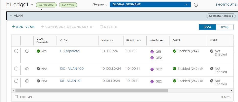
You can add or edit VLANs, or add secondary IP addresses. You can also delete the selected VLAN.
- Select IPv4 or IPv6 button to display the respective list of VLANs.
- To add a VLAN, select + Add VLAN.
Figure 3. Adding VLAN Parameters 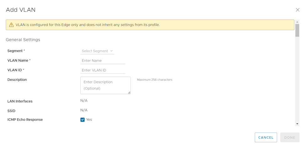
- Configure the Add VLAN settings from the table below.
Table 8. Add VLAN Settings Option Descriptions Option Description Segment Select a segment from the drop-down menu. This assigns the VLAN to the selected segment. VLAN Name Enter a unique name for the VLAN. VLAN Id Enter the VLAN ID. Assign Overlapping Subnets LAN IP Addressing can be managed from the assigned Profile of the Edge. When this check box is selected, the values for Edge LAN IP Address, Cidr Prefix, and DHCP are inherited from the associated Profile and are read-only. The Network address is automatically set based on the subnet mask and CIDR value. Note: Overlapping subnets for the VLAN are supported only for SD-WAN to SD-WAN traffic and SD-WAN to Internet traffic.Edge LAN IP Address Enter the LAN IP address of the Edge. Cidr Prefix Enter the CIDR prefix for the LAN IP address. Network Enter the IP address of the Network. Advertise Select the check box to advertise the VLAN to other branches in the network. ICMP Echo Response Select the check box to enable the VLAN to respond to ICMP echo messages. VNF Insertion Select the check box to insert a VNF to the VLAN, which redirects traffic from the VLAN to the VNF. To enable VNF Insertion, ensure that the selected segment is mapped with a service VLAN. Multicast This option is enabled only when you have configured multicast settings for the Edge. You can configure the following multicast settings for the VLAN. - IGMP
- PIM
Select toggle advanced multicast settings to set the timers:- PIM Hello Timer
- IGMP Host Query Interval
- IGMP Max Query Response Value
Fixed IPs Enter the IP addresses tied to specific MAC Addresses for the VLAN. LAN Interfaces Configure VLAN LAN Interfaces. SSID Configure VLAN Wi-Fi SSIDs. DHCP Type Choose one of the following DHCP settings: Enabled – Enables DHCP with the Edge as the DHCP server. Configure the following details:- DHCP Start – Enter a valid IP address available within the subnet.
- Num. Addresses – Enter the number of IP addresses available on a subnet in the DHCP Server.
- Lease Time – Select the period of time from the drop-down list. This is the duration the VLAN is allowed to use an IP address dynamically assigned by the DHCP Server.
- Options – Add pre-defined or custom DHCP options from the drop-down list. The DHCP option is a network service passed to the clients from the DHCP server. For a custom option, enter the code, data type, and value.
Relay – Enables DHCP with the DHCP Relay Agent installed at a remote location. If you choose this option, configure the following:- Source from Secondary IP(s) – When you select this check box, the DHCP discover/Request packets from the client will be relayed to the DHCP Relay servers sourced from the primary IP address and all the secondary IP addresses configured for the VLAN. The reply from the DHCP Relay servers will be sent back to the client after rewriting the source and destination. The DHCP server will receive the request from both the primary and secondary IP addresses and the DHCP client can get multiple offers from primary subnet and secondary subnets.
When this option is not selected, the DHCP discover/Request packets from the client will be relayed to the DHCP Relay servers sourced only from the primary IP address.
- Relay Agent IP(s) – Specify the IP address of Relay Agent. Select the Plus( + ) icon to add additional IP addresses.
Not Enabled – Deactivates DHCP.
OSPF This option is available only when you have configured OSPF at the Profile level for the selected Segment. Select the check box and choose an OSPF area from the drop-down list. Note: The OSPFv2 configuration supports only IPv4. The OSPFv3 configuration supports only IPv6, which is only available in the 5.2 release.For additional information on OSPF settings and OSPFv3, see Activate OSPF for Edges.
- After configuring the required parameters, select the Add VLAN button.
Edit VLANs
- To edit the existing VLAN settings inherited from the Profile, select the Edit link corresponding to the VLAN.
- Select the Override check boxes to override the VLAN settings inherited from the Profile.
Figure 4. Editing VLAN Parameters 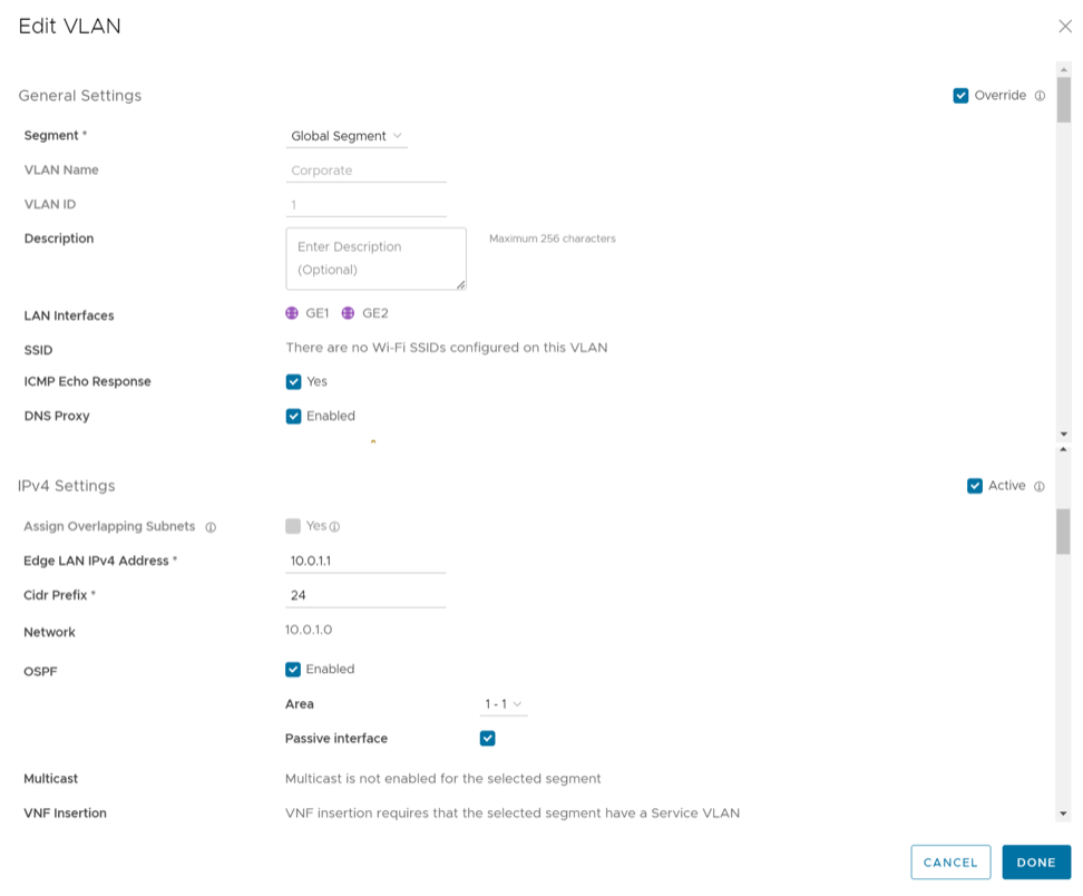 Note: You cannot override the Profile VLAN name and ID.
 - After modifying the required parameters, select Done VLAN.
For Configuring VLANs at the Profile level, see Configure VLAN for Profiles.
Secondary IP Addresses
The VLAN is configured with a primary IP address. You can add secondary IP addresses to the VLAN, to increase the number of host addresses for a network segment. To add secondary IP addresses to the VLAN, select Add Secondary IP.
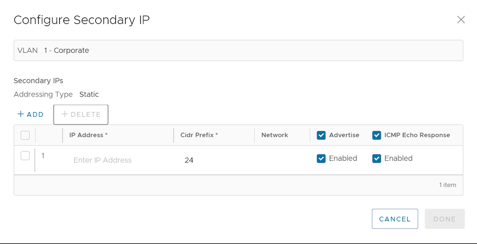
A row to configure a secondary IP displays, as shown in the image above. Configure the Secondary IP VLAN settings from the table below.
| Option | Description |
|---|---|
| Addressing Type | By default, the addressing type is Static and you cannot modify the type. |
| IP Address | Enter the secondary IP address for the selected VLAN. |
| Cidr Prefix | Enter the CIDR prefix for the IP address. |
| Network | Displays the IP address of the Network, which is auto-generated from the secondary IP address and CIDR prefix. |
| Advertise | Select the check box to advertise the secondary IP address network of the VLAN to other branches in the network. |
| ICMP Echo Response | Select the check box to enable the VLAN with the secondary IP address to respond to ICMP echo messages. |
Select Done when complete. On the Device settings screen, select Save Changes to save the settings.
Loopback Interfaces Configuration
A loopback interface is a logical interface that allows you to assign an IP address to identify a VeloCloud Edge.
You can configure loopback interfaces only for Edges running on version 4.3 and above. The Configure Loopback Interfaces area is not available for Edges on version 4.2 or lower. For such Edges, you must configure Management IP address. For details, refer to Configure Management IP Address for Profiles.
Loopback Interfaces—Benefits
- As loopback interfaces are logical interfaces that are always up and reachable, you can use these interfaces for diagnostic purposes as long as there is layer 3 reachability to at least one physical interface.
- Loopback interfaces can be used as source interface for BGP. This ensures that when the BGP interface state flaps, the BGP membership does not flap if there is at least one layer 3 connection available.
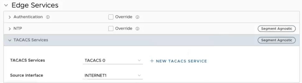
- Loopback interface IP address can be used as the source IP address for the various services such as Orchestrator Management Traffic, Authentication, DNS, NetFlow, Syslog, TACACS, BGP, and NTP. As loopback interfaces are always up and reachable, these services can receive the reply packets, if at least one physical interface configured for the Edge has layer 3 reachability.
Loopback Interfaces—Limitations
- Only IPv4 addresses can be assigned for loopback interfaces.
- Loopback interfaces can be configured only for Edges. They cannot be configured for Profiles.
- Loopback interfaces must be configured only after the Edge activation is successful.
- For any Edge that is not activated, the version of the customer operator profile is validated based on which either the Management IP Address section or the Loopback Interfaces section is visible. For example, if the version of the customer operator profile is 4.3 or above, the Loopback Interfaces section is visible at the Edge-level. Whereas, if the version of the customer operator profile is 4.2 or lower and the Edge is not activated, the Management IP Address section is visible at the Edge-level and Profile-level.
- Loopback interface IDs must be unique across all segments within an Edge and must start from 1, as Zero (0) is not supported.
- If you choose to configure loopback interfaces and Orchestrator management traffic through API, the default configuration keys for these two properties are not available. You must modify the update Configuration Module API to configure the loopback interface and management traffic source interface selection.
- You can access loopback interfaces only through SSH. Loopback interface access through local Web UI is not supported.
- Consider the following when you upgrade or downgrade your Edges:
- If the Management IP address that is configured either at the Profile-level or at the Edge-level is not the default IP address (
192.168.1.1) and when the Edge is upgraded to version 4.3 or above, the loopback interface is automatically created at the Edge-level with the configured Management IP address as the IP address of the loopback interface. - Consider that you have upgraded your Orchestrator to version 4.3 or above, whereas the Edge still runs on version 4.2 or lower. If you update the Management IP address configuration either at the Profile-level or at the Edge-level, and then upgrade your Edge to version 4.3 or above, all changes that you made to the Management IP address configuration will be lost.
- When the Edge is downgraded to a version lower than 4.3, the Management IP address that was configured before the upgrade will be retained at the Profile-level and at the Edge-level.
- Any changes made to the loopback interface configuration will be lost after the Edge downgrade.
- For example, consider that you had the Management IP address as
1.1.1.1. When you upgrade your Edge to version 4.3 or above, the same IP address,1.1.1.1will be the IP address of the loopback interface at the Edge-level. Then, you change the loopback interface IP address to2.2.2.2. When you downgrade your Edge to a version lower than 4.3, you will notice that the Management IP address at the Edge-level will still be1.1.1.1and the Management IP address at the Profile-level will be empty.
- If the Management IP address that is configured either at the Profile-level or at the Edge-level is not the default IP address (
Configure a Loopback Interface for an Edge
For information about the rules and notes that you must consider before you configure a loopback interface, see Loopback Interfaces—Limitations.
- In the SD-WAN service of the Enterprise portal, go to .
- Select the link to an Edge for which you want to configure the loopback interface or select the View link in the Device column of the Edge. The configuration options for the selected Edge are displayed in the Device tab.
- Scroll down to the Connectivity category and select Loopback Interfaces.
Figure 6. Loopback Interfaces 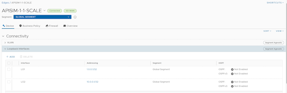
- Select + Add and in the Add Loopback pop-up window, configure the required loopback settings as described in the following table.
Figure 7. Adding a Loopback Interface 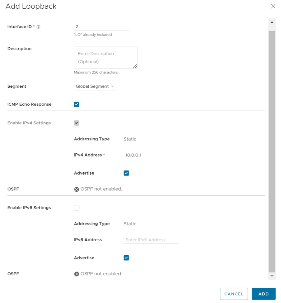
Table 10. Loopback Parameters Field Description Interface ID Enter a unique ID for the loopback interface. The ID must be unique across all segments within an Edge and must start from 1, as Zero (0) is not supported. Segment Select a segment from the drop-down list. The loopback interface belongs to the selected segment. ICMP Echo Response Select the check box to enable the loopback interface to respond to ICMP echo messages. IPv4 Settings Addressing Type By default, the addressing type is Static and you cannot modify the type. IP Address Enter the IPv4 address for the loopback interface. CIDR Prefix The CIDR prefix for the loopback interface IPv4 address. The default value is /32. You cannot modify the default value.Advertise Select the check box to advertise the loopback interface to other branches in the network. OSPF Select the check box and choose an OSPF area from the drop-down list. The loopback interface IP address is advertised in the selected OSPF area. Note: The OSPFv2 configuration supports only IPv4. The OSPFv3 configuration supports only IPv6, which is only available in the 5.2 release.Note: This option is enabled only when you have configured OSPF for the segment that you have selected for the loopback interface.For additional information on OSPF settings and OSPFv3, see Activate OSPF for Edges.
IPv6 Settings Addressing Type By default, the addressing type is Static and you cannot modify the type. IP Address Enter the IPv6 address for the loopback interface. CIDR Prefix The CIDR prefix for the loopback interface IP address. The default value is /128. You cannot modify the default value.Note: You can select the Active check boxes for the IPv4 and IPv6 settings, to enable the corresponding addressing type for the Interface. By default, the option is enabled for IPv4 settings. - Select Add.
- Select Save Changes.
At any point in time, you can choose to edit the loopback interface settings by selecting the Address link, except CIDR Prefix and Interface ID.
If you delete a loopback interface, the Source Interface field for all the services for which you have selected the loopback interface, is reset to Auto.
- If the loopback interface ID is not found in the Edge.
- If you use older versions of APIs to configure the Edge, sometimes the Edge may not receive the key for source IP address for the services.
- Any non-WAN interface that is advertised is prioritized.
- Among the non-WAN interfaces that are advertised, the source interface selection is based on the following order of priority—Loopback interfaces, VLAN interfaces, or any routed interfaces.
- If there are more than one interfaces of the same type configured and advertised, the interface with the lowest interface ID is selected.
For example, if you have two loopback interfaces (LO3 and LO4), one VLAN interface (VLAN2), and two routed interfaces (GE1 and GE2) configured and advertised, and if the Source Interface field for any service is set to Auto, the Edge selects LO3 as the source interface.
| Services/Settings | For details, refer to ... |
|---|---|
| Orchestrator Management Traffic | Configure Management Traffic for Edges |
| Authentication Settings | Configure Authentication Settings for Profiles |
| DNS Settings | Configure DNS for Profiles |
| Netflow Settings | Configure Netflow Settings for Edges |
| Syslog Settings | Configure Syslog Settings for Edges |
| BGP Settings | Configure BGP from Edge to Underlay Neighbors for Profiles |
| NTP Settings | Configure NTP Settings for Edges |
Configure Management Traffic for Edges
You can configure the Management Traffic for the Edge to transmit the traffic to VeloCloud Edge Cloud Orchestrator.
- In the SD-WAN service of the Enterprise portal, go to .
- Select the link to an Edge for which you want to configure the Orchestrator Management Traffic or select the View link in the Device column of the Edge. The configuration options for the selected Edge are displayed in the Device tab.
- Scroll down to the Connectivity category and select and expand the Management Traffic area.
Figure 8. Management Traffic 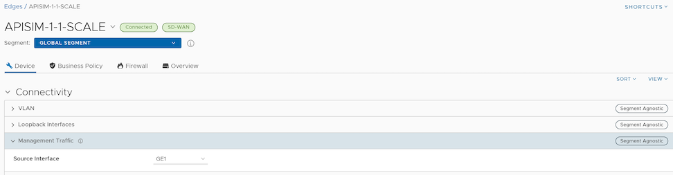
- From the Source Interface drop-down menu, select an Edge interface that is configured for the segment. This interface will be the source IP for the Edge to transmit the traffic to VeloCloud Edge Cloud Orchestrator. By default, Auto is selected.
When the Edge transmits the traffic, the packet header has the IP address of the selected source interface, whereas the packets can be sent through any interface based on the destination route.
Configure Address Resolution Protocol Timeouts for Edges
At the Edge level, you can override the Address Resolution Protocol (ARP) Timeout settings inherited from a Profile by selecting the Override check box.
- In the SD-WAN service of the Enterprise portal, go to . The Edges page displays the existing Edges.
- Select the link to an Edge you want to override L2 settings or select the View link in the Device column of the Edge. The Device tab displays the configuration options for the selected Edge.
- Under the Connectivity category, select ARP Timeouts and select the Override check box.
Figure 9. Configuring ARP Timeouts 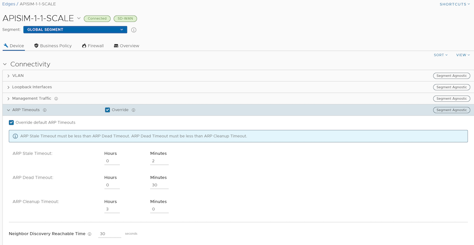
- Select the Override default ARP Timeouts check box and then override the various ARP timeouts inherited from the Profile as follows:
Table 12. ARP Timeouts Field Descriptions Field Description ARP Stale Timeout The allowable value ranges from 1 minute to 23 hours and 58 minutes. ARP Dead Timeout The allowable value ranges from 2 minutes to 23 hours and 59 minutes. ARP Cleanup Timeout The allowable value ranges from 3 minutes to 24 hours. Note: The ARP timeout values can only be in increasing order of minutes. For detailed descriptions for Stale, Dead, and Cleanup timeouts, see Configure Address Resolution Protocol Timeouts for Profiles.Note: To set the default ARP timeout values at the Edge level, clear the Override default ARP Timeouts checkbox. - Select Save Changes.
Configure Interface Settings for Edges
An Edge has different types of interfaces. By default, the interface configuration settings of an Edge are inherited from the associated Profile. You can modify and configure more settings for each Edge.
The interface settings options vary based on the Edge model. For additional information on different Edge models and deployments, see Configure Interface Settings.
To configure interface settings for a specific Edge, perform the following steps:
- In the SD-WAN service of the Enterprise portal, select . The Edges page displays the existing Edges.
- Select the link to an Edge or select the View link in the Device column of the Edge. The configuration options for the selected Edge are displayed in the Device tab.
- In the Connectivity category, expand Interfaces.
- The different types of interfaces available for the selected Edge are displayed. Select the link to an interface to edit the settings. The Interface settings screen as shown below appears.
Figure 10. Configuring Interface Settings 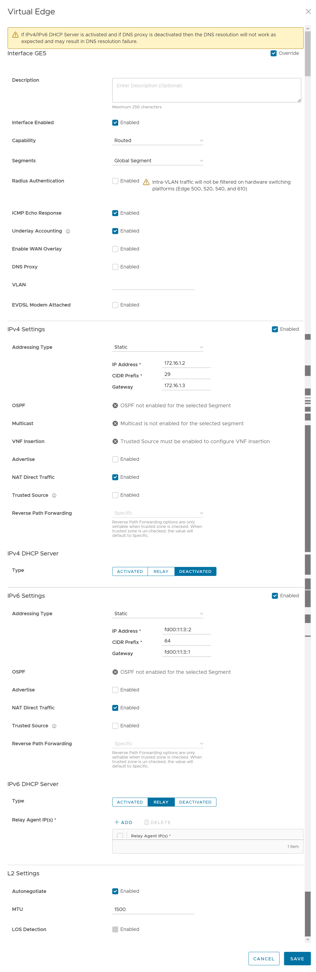 You can edit the settings for the following types of interfaces, based on the Edge model:
- Switch Port
- Routed Interface
- WLAN Interface
You can also add Subinterface, Secondary IP address, and Wi-Fi SSID based on the Edge model.
- You can configure the following settings for a Routed interface of an Edge.
Table 13. Routed Interface of an Edge Option Descriptions Option Description Description Enter a description. This field is optional. Interface Enabled This option is activated by default. If required, you can deactivate the interface. When deactivated, the interface is not available for any communication. Capability For a Switch Port, the option Switched is selected by default. You can choose to convert the port to a routed interface by selecting the option Routed from the drop-down menu. Segments By default, the configuration settings are applicable to all the segments. Radius Authentication Deactivate the Enable WAN Overlay check box to configure Radius Authentication. Select the Radius Authentication check box and add the MAC addresses of pre-authenticated devices. ICMP Echo Response This check box is selected by default. This helps the interface to respond to ICMP echo messages. You can deactivate this option for security purposes. Underlay Accounting This check box is selected by default. If a private WAN overlay is defined on the interface, all underlay traffic traversing the interface are counted against the measured rate of the WAN link to prevent over-subscription. Deactivate this option to avoid this behavior. Note:- Underlay Accounting is supported for both, IPv4 and IPv6 addresses.
- Enabling underlay configuration for LAN is not recommended.
Enable WAN Overlay Select the check box to activate WAN overlay for the interface. DNS Proxy The DNS Proxy feature provides additional support for Local DNS entries on the Edge, to point certain device traffic to specific domains. You can activate or deactivate this option, irrespective of IPv4 or IPv6 DHCP Server setting. Note: This check box is available only for a Routed Interface and a Routed Subinterface.VLAN For an Access port, select an existing VLAN from the drop-down menu. For a Trunk port, you can select multiple VLANs and select an untagged VLAN. EVDSL Modem Attached Select this check box to activate an EVDSL Modem which is connected to one of the Ethernet ports on the Edge. IPv4 Settings Select the Enable check box and configure the IPv4 settings. For additional information, see IPv4 Settings section below. IPv6 Settings Select the Enable check box and configure the IPv6 settings. For additional information, see IPv6 Settings section below. L2 Settings Autonegotiate This option is selected by default. When selected, Auto negotiation allows the port to communicate with the device on the other end of the link to determine the optimal duplex mode and speed for the connection. Speed This option is available only when Autonegotiate is not selected. Select the speed that the port has to communicate with other links. By default, 100 Mbps is selected. Duplex This option is available only when Autonegotiate is not selected. Select the mode of the connection as Full duplex or Half duplex. By default, Full duplex is selected. MTU The default MTU size for frames received and sent on all routed interfaces is 1500bytes. You can change the MTU size for an interface.LOS Detection This option is available only for a routed interface of an Edge. Select the check box to activate Loss of Signal (LoS) detection by using ARP monitoring. For additional information, see HA LoS Detection on Routed Interfaces. Note: You can select the check box only when you have activated High Availability on the Edge.
IPv4 Settings
Select the Enabled check box to configure the following IPv4 Settings:
| Option | Description |
|---|---|
| Addressing Type | Select an addressing type:
Note: 31-bit prefixes are supported for IPv4 as per RFC 3021.
|
| OSPF | This option is available only when you have configured OSPF at the Profile level for the selected Segment. Select the check box and choose an OSPF area from the drop-down menu.
Select Advanced settings to configure the advanced interface settings for the selected OSPF area. Note: When configuring advanced OSPF area settings for a routed interface, the BFD configuration is supported only for global segments.
The OSPFv2 configuration supports only IPv4. The OSPFv3 configuration supports only IPv6.
For additional information on OSPF settings and OSPFv3, see Activate OSPF for Profiles.Note: OSFPv3 is only available in the 5.2 release.
|
| Multicast | This option is available only when you have configured multicast settings for the selected Segment. You can configure the following multicast settings for the selected interface.
Select toggle advanced multicast settings to configure the following timers:
Note: Currently, Multicast Listener Discovery (MLD) is deactivated. Hence, Edge does not send the multicast listener report when IPv6 address is assigned to interface. If there is a snooping switch in the network then not sending MLD report may result in Edge not receiving multicast packets which are used in Duplicate Address Detection (DAD). This results in DAD success even with duplicate address.
|
| VNF Insertion | You must deactivate WAN Overlay and select the Trusted Source check box to activate VNF Insertion. When you insert the VNF into Layer 3 interfaces or subinterfaces, the system redirects traffic from the Layer 3 interfaces or subinterfaces to the VNF. |
| Advertise | Select the check box to advertise the interface to other branches in the network. |
| NAT Direct Traffic | Select the check box to apply NAT for IPv4 to network traffic sent from the interface.
CAUTION: It is possible that an older version of the SASE Orchestrator inadvertently configured NAT Direct on a main interface with either a VLAN or subinterface configured. If that interface is sending direct traffic one or hops away, the customer would not observe any issues because the NAT Direct setting was not being applied. However, when an Edge is upgraded to 5.2.0 or later, the Edge build includes a fix for the issue (Ticket #92142) with NAT Direct Traffic not being properly applied, and there is a resulting change in routing behavior since this specific use case was not implemented in prior releases.
In other words, because a 5.2.0 or later Edge now implements NAT Direct in the expected manner for all use cases, traffic that previously worked (because NAT Direct was not being applied per the defect) may now fail because the customer never realized that NAT Direct was checked for an interface with a VLAN or subinterface configured. As a result, a customer upgrading their Edge to Release 5.2.0 or later should first check their Profiles and Edge interface settings to ensure NAT Direct is configured only where they explicitly require it and to deactivate this setting where it is not, especially if that interface has a VLAN or subinterface configured. |
| Trusted Source | Select the check box to set the interface as a trusted source. |
| Reverse Path Forwarding | You can choose an option for Reverse Path Forwarding (RPF) only when you have selected the Trusted Source check box. This option allows traffic on the interface only if return traffic can be forwarded on the same interface. This helps to prevent traffic from unknown sources like malicious traffic on an Enterprise network. If the incoming source is unknown, then the packet is dropped at ingress without creating flows. Select one of the following options from the drop-down menu:
|
- Activated: Activates DHCP with the Edge as the DHCP server. If you choose this option, configure the following details:
- DHCP Start: Enter a valid IP address available within the subnet.
- Num. Addresses: Enter the number of IP addresses available on a subnet in the DHCP Server.
- Lease Time: Select the period of time from the drop-down menu. This is the duration the VLAN is allowed to use an IP address dynamically assigned by the DHCP server.
- Options: Select Add to add pre-defined or custom DHCP options from the drop-down menu. The DHCP option is a network service passed to the clients from the DHCP server. Choose a custom option and enter the code, data type, and value.
- Relay – Allows exchange of DHCPv4 messages between client and server. If you choose this option, configure the following:
- Relay Agent IP(s): Specify the IP address of Relay Agent. Select Add to add more IP addresses.
- Deactivated – Deactivates the DHCP server.
IPv6 Settings
| Option | Description |
|---|---|
| Addressing Type | Select an addressing type:
|
| OSPF | This option is available only when you have configured OSPF at the Profile level for the selected Segment. Select the check box and choose an OSPF area from the drop-down menu. Select Advanced Settings to configure advanced interface settings for the selected OSPF area.
Note: When configuring advanced OSPF area settings for a routed interface, the BFD configuration is supported only for global segments.
The OSPFv2 configuration supports only IPv4. The OSPFv3 configuration supports only IPv6, which is only available in the 5.2 release.
For more information on OSPF settings and OSPFv3, see Activate OSPF for Profiles.Note: OSFPv3 is only available in the 5.2 release.
|
| Advertise | Select the check box to advertise the interface to other branches in the network. |
| NAT Direct Traffic | Select the check box to apply NAT for IPv6 to network traffic sent from the interface.
CAUTION: It is possible that an older version of the SASE Orchestrator inadvertently configured NAT Direct on a main interface with either a VLAN or subinterface configured. If that interface is sending direct traffic one or hops away, the customer would not observe any issues because the NAT Direct setting was not being applied. However, when an Edge is upgraded to 5.2.0 or later, the Edge build includes a fix for the issue (Ticket #92142) with NAT Direct Traffic not being properly applied, and there is a resulting change in routing behavior since this specific use case was not implemented in prior releases.
In other words, because a 5.2.0 or later Edge now implements NAT Direct in the expected manner for all use cases, traffic that previously worked (because NAT Direct was not being applied per the defect) may now fail because the customer never realized that NAT Direct was checked for an interface with a VLAN or subinterface configured. As a result, a customer upgrading their Edge to Release 5.2.0 or later should first check their Profiles and Edge interface settings to ensure NAT Direct is configured only where they explicitly require it and to deactivate this setting where it is not, especially if that interface has a VLAN or subinterface configured. |
| Trusted Source | Select the check box to set the Interface as a trusted source. |
| Reverse Path Forwarding | You can choose an option for Reverse Path Forwarding (RPF) only when you have selected the Trusted Source check box. This option allows traffic on the interface only if return traffic can be forwarded on the same interface. This helps to prevent traffic from unknown sources like malicious traffic on an Enterprise network. If the incoming source is unknown, then the packet is dropped at ingress without creating flows. Select one of the following options from the drop-down menu:
|
- Activated: Activates DHCPv6 with the Edge as the DHCPv6 server. If you choose this option, configure the following details:
- DHCP Start: Enter a valid IPv6 address available within the subnet.
- Num. Addresses: Enter the number of IP addresses available on a subnet in the DHCPv6 Server.
- Lease Time: Select the period of time from the drop-down list. This is the duration the VLAN is allowed to use an IPv6 address dynamically assigned by the DHCPv6 Server.
- DHCPv6 Prefix Delegation: Select Add to assign prefixes chosen from a global pool to DHCP clients. Enter the prefix pool name along with the prefix start and end details.
- Options – Select Add to add pre-defined or custom DHCP options from the drop-down menu. The DHCP option is a network service passed to the clients from the DHCP server. Choose a custom option and enter the code, data type, and value.
- Relay – Allows exchange of DHCPv6 messages between client and server. If you choose this option, configure the following:
- Relay Agent IP(s): Specify the IP address of Relay Agent. Select Add to add more IP addresses.
Starting from the 5.2.0 release, VeloCloud Edge supports the DHCPv6 Relay feature. This allows the DHCPv6 clients to communicate with a remote DHCPv6 server. It is mostly similar to the DHCPv4 Relay feature, except that DHCPv6 uses separate message types to allow the Relay agents to insert their own options or to identify the outgoing interface for the reply packet. To activate this feature on an Edge, you must activate IPv6 on the LAN interface of that Edge.
Note:- You must provide the Server IP address as the Relay Agent IP address on the customer-facing interface.
- If this interface belongs to a non-global segment, the Server must be reached through the same non-global segment.
- Relay Agent IP(s): Specify the IP address of Relay Agent. Select Add to add more IP addresses.
- Deactivated: Deactivates the DHCP server.
Router Advertisement Host Settings: The Router Advertisement (RA) parameters are available only when you activate IPv6 Settings, and then choose the Addressing Type as DHCP Stateless or DHCP Stateful.
| Option | Description |
|---|---|
| MTU | Accepts the MTU value received through Route Advertisement. If you turn off this option, the MTU configuration of the interface is considered. |
| Default Routes | Installs default routes when Route Advertisement is received on the interface. If you turn off this option, then there are no default routes available for the interface. |
| Specific Routes | Installs specific routes when Route Advertisement receives route information on the interface. If you turn off this option, the interface does not install the route information. |
| ND6 Timers | Accepts ND6 timers received through Route Advertisement. If you turn off this option, default ND6 timers are considered. The default value for NDP retransmit timer is 1 second and NDP reachable timeout is 30 seconds. |
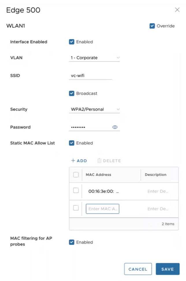
Wi-Fi Access Control based on MAC Address
Wi-Fi Access Control can be used as an additional layer of security for wireless networks. When activated, only known and approved MAC addresses are permitted to associate with the base station.
- In the SD-WAN service of the Enterprise portal, select and choose an existing WLAN interface to configure the following parameters.
| Option | Description |
|---|---|
| Interface Enabled | Select the check box to activate the interface. |
| VLAN | Choose the VLAN ID from the drop-down menu. |
| SSID | Enter the SSID. |
| Security | Select either WPA2/Enterprise or WPA2/Personal as the Security option. |
| Static MAC Allow List | Select the check box to permit only the listed MACs to associate with the access point.
When Static MAC Allow List is configured, only the Mac addresses specified in the list are permitted to associate with the access point. |
| Radius ACL Check | Select the check box to associate the MAC address with a RADIUS server. If an access-accept is received, the MAC is allowed to associate with the access point.
Note: RADIUS ACL checks are limited to WPA2/Enterprise security mode.
|
| Add | Select to enter a new MAC address. |
| Delete | Select to remove an existing MAC address. |
| MAC filtering for AP Probes | Enabling MAC Filtering for AP probes prevents probes from unapproved MAC Addresses from actively discovering AP parameters. When the SSID is not broadcast, this can assist in preventing unknown stations from connecting to the network. Some devices are known to use random MAC addresses for probing regardless of AP settings and probe filtering may cause these devices to fail to discover or connect to the network even if their device MAC has been approved. |
Configure DHCP Server on Routed Interfaces
You can configure DHCP server on a Routed Interface in an Edge.
To configure DHCP Server settings:
- Select the Edit option for the Routed interface that you want to configure DHCP settings.
Figure 13. Edit Interface Settings 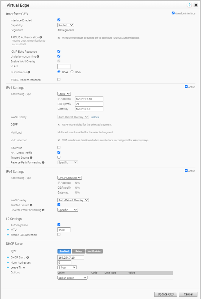
Enable RADIUS on a Routed Interface
- A RADIUS server must be configured and added to the Edge. See Configure Authentication Services.
- RADIUS may be enabled on any routed interface. This includes the interfaces for any Edge model, except for the LAN 1-8 ports on Edge models 500/520/540.
RADIUS can be enabled on any interface that is configured as a routed interface. The Edge supports both username/password (EAP-MD5) and certificate (EAP-TLS) based 802.1x Authentication methods.
Enabling RADIUS on a Routed Interface
- Select the link to the routed interface that you want to configure RADIUS authentication.
Figure 14. RADIUS Authentication 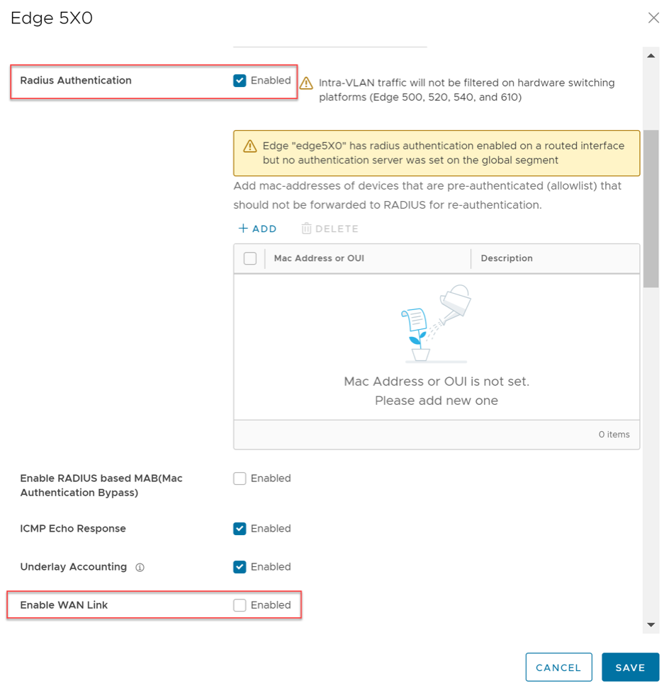
Configure RADIUS Authentication for a Switched Interface
- A RADIUS server must be configured and added to the Edge. See Configure Authentication Services.
- RADIUS may be configured on any switched interface.
This section discusses configuring user authentication with a RADIUS server using the 802.1x protocol on an Edge's switched interface through the use of a VLAN associated with that switched interface.
Beginning with SD-WAN Release 5.1.0, a user can configure RADIUS authentication to use an Edge's switched interface as they already had been able to do for a routed interface.
The SD-WAN Edge supports both username/password (EAP-MD5) and certificate (EAP-TLS) based 802.1x Authentication methods.
Configuring RADIUS Authentication on a Switched Interface
- Select the link to the switched interface (for example GE2 as shown in the following screenshot) that you want to configure RADIUS authentication.
Figure 15. Interfaces 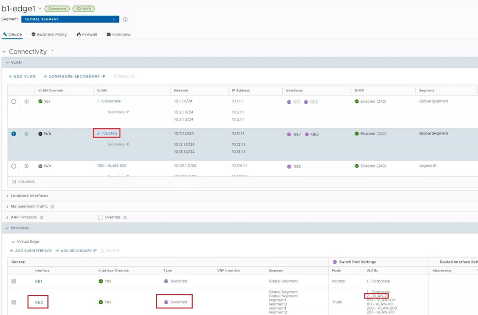
- The Interface settings dialog appears. Add the VLAN where RADIUS authentication will be used to the switched interfaces list of VLANs and select Save.
Figure 16. Add VLAN 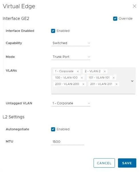
- On the Edit VLAN screen, select the RADIUS Authentication check box.
Figure 17. Edit VLAN 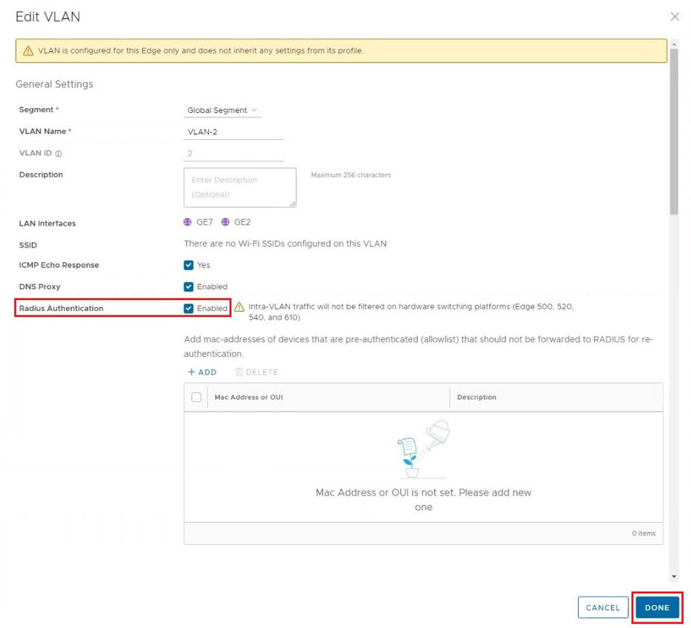
MAC Address Bypass (MAB) for RADIUS-based Authentication
- A RADIUS server must be configured and added to the Edge. See the topic Configure Authentication Services.
- The RADIUS server must have a list of MAC addresses to be bypassed to take advantage of the MAB feature.
- RADIUS authentication must be configured on an Edge's routed interface or switched interface via a VLAN either at the Profile or Edge level.
On routed interfaces customers can check MAC addresses against a RADIUS server to bypass 802.1x for LAN devices that do not support 802.1x authentication. MAB simplifies IT operations, saves time, and enhances scalability by no longer requiring customers to manually configure every MAC address that may need authentication.
- L2 traffic will not trigger RADIUS MAB.
- L2 traffic will not be forwarded on Linux-based switches until routed traffic is seen. Hardware switches already do not filter pure L2 traffic, and this limitation remains unchanged.
- If no routed traffic is observed and RADIUS MAB times out (default is 30 minutes), L2 traffic will again be blocked.
- Additional hooks to check 802.1x status for self-destined packets may cause performance degradation when 802.1x is enabled.
- Traffic destined to self and managed entirely by Linux will no longer be filtered prior to 802.1x authentication (DHCP, DNS, ssh, and so forth).
Activating MAB for Routed Interface
- In the Connectivity category, click and expand Interfaces.
The Interfaces section displays the different types of Interfaces available for the selected Edge.
Figure 18. Configure Interfaces 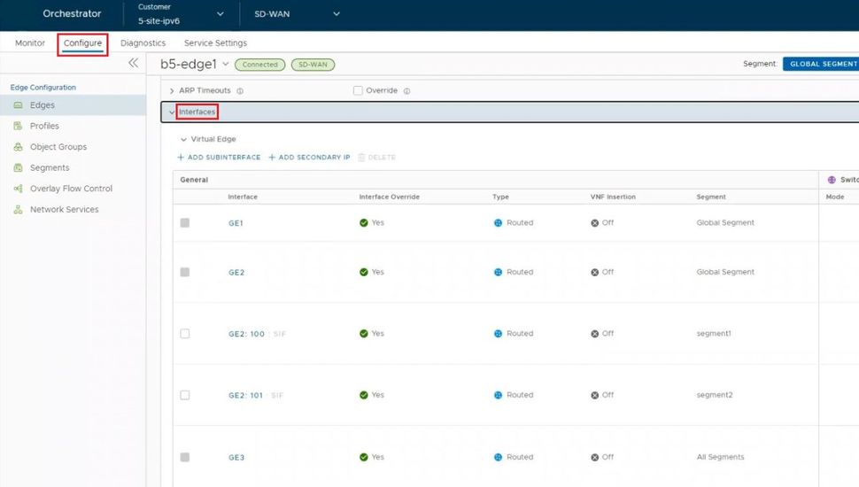
- Click the Interface to edit the Routed interface that is configured for RADIUS authentication.
Figure 19. Edit the Routed Interface 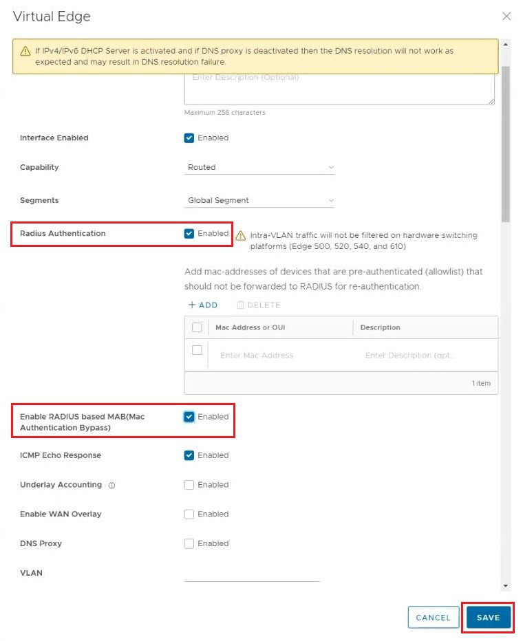
Activating MAB for Switched Port using a VLAN
- The VLAN section displays the VLAN's configured for the selected Edge.
Figure 20. VLAN 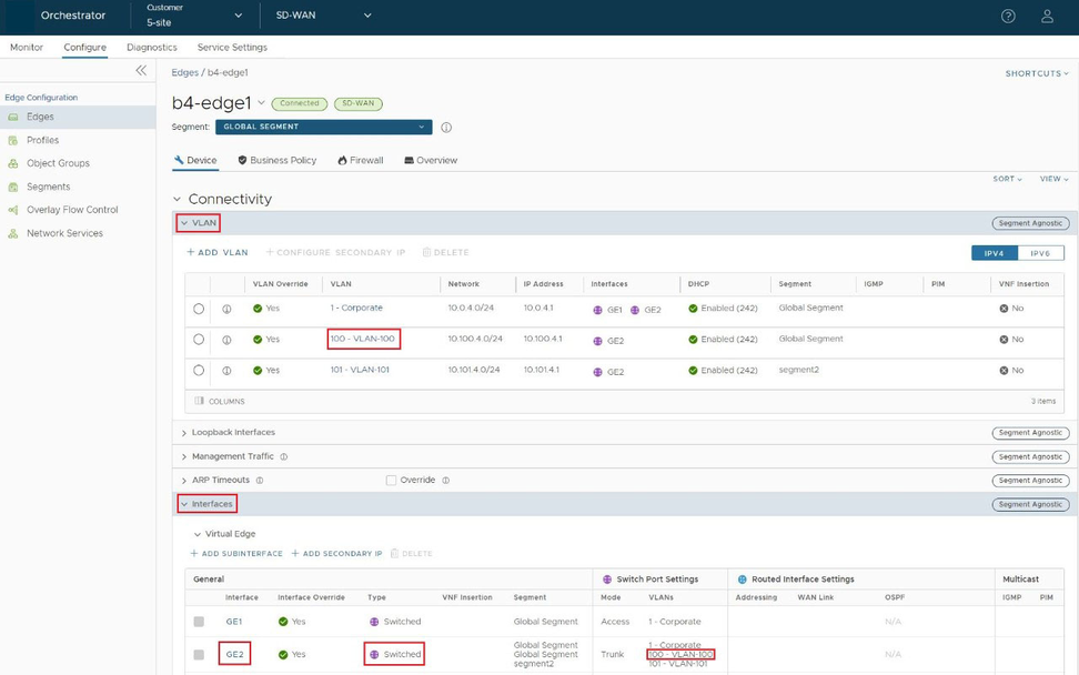
- Click the VLAN to edit the VLAN and configure is for RADIUS authentication.
Figure 21. Edit VLAN 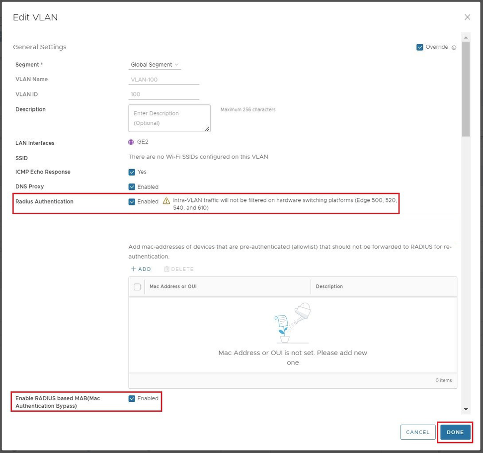
- Click the Interface to edit the Switched interface so that you can assign the VLAN configured for RADIUS.
Figure 22. Edit the Switched Interface 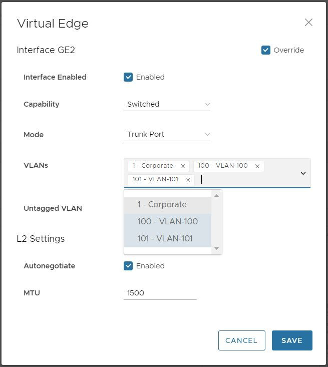
Configure Edge LAN Overrides
An Edge has different types of Interfaces. By default, the Interface configuration settings of an Edge are inherited from the associated Profile. At the Edge level, you can override the LAN settings inherited from the Profile.
To override the LAN settings for an Edge:
- Select the link to a LAN Interface to edit the settings. The LAN Interface settings screen as shown below appears.
Figure 23. LAN Interface Settings 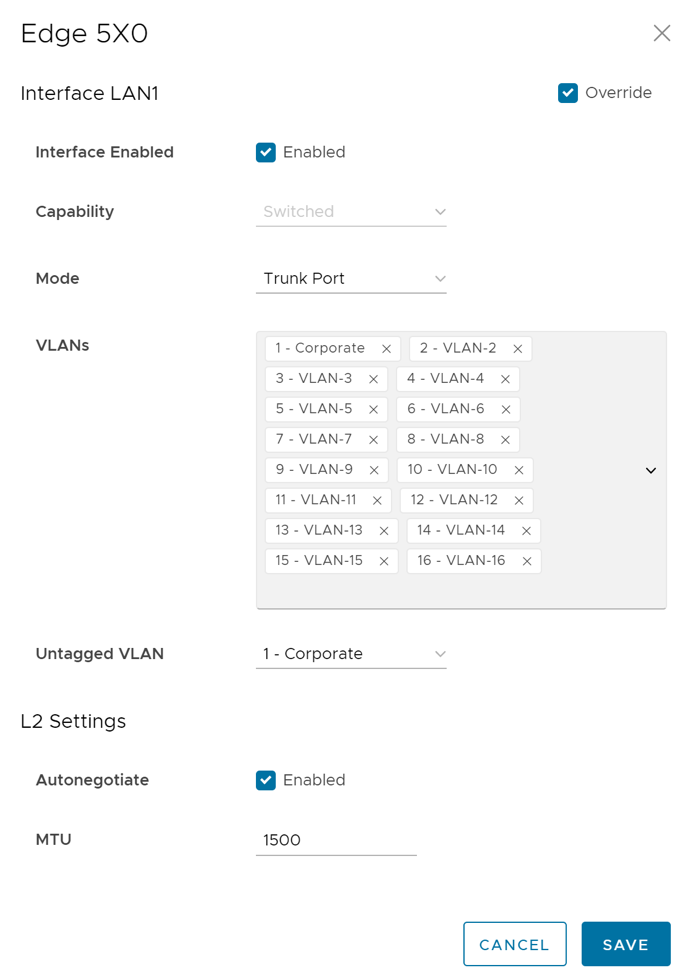
Configure Edge WLAN Overrides
An Edge has different types of Interfaces. By default, the Interface configuration settings of an Edge are inherited from the associated Profile. At the Edge level, you can override the WLAN settings inherited from the Profile.
To override the WLAN settings for an Edge:
- The different types of Interfaces available for the selected Edge are displayed. Select the link to a WLAN Interface to edit the settings.
The WLAN Interface settings screen as shown below appears.
Figure 24. WLAN Interface Settings 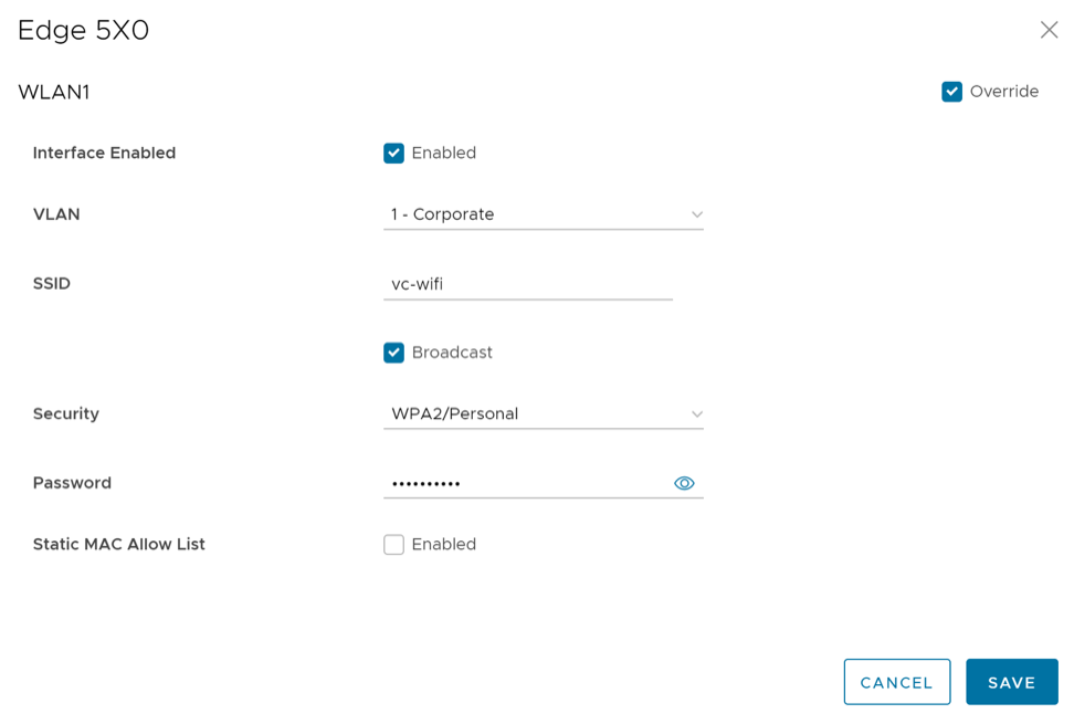
Configure Edge WAN Overlay Settings
The WAN Overlay settings enables you to add or modify a User-Defined WAN Overlay.
- Private Overlay: This is required on a private network where you want to have the Edge build overlay VCMP tunnels directly between private IP addresses assigned to each Edge on the private network.
Note: In a Partner Gateway setup with handoff Interface configured, when an Edge with private Interface has both IPv4 and IPv6 user-defined overlays, the Edge tries to establish IP tunnels towards the public IP address of the Gateway based on the tunnel preference.
- Public Overlay: This is useful when you want to set a custom VLAN or source IP address and Gateway address for the VCMP tunnels, to reach VeloCloud Gateways over the Internet, as determined by the Orchestrator.
You can also modify or delete an existing auto-detected WAN Overlay that has been detected on a routed interface. An auto-detected overlay is available only when the Edge has successfully made a VCMP tunnel over a routed interface configured with WAN Overlay to Gateways designated by the Orchestrator.
To configure WAN Overlay settings for a specific Edge, perform the following steps:
- In the Connectivity category, select Interfaces.
The WAN Link Configuration section displays the existing Overlays.
Figure 25. WAN Link Configuration 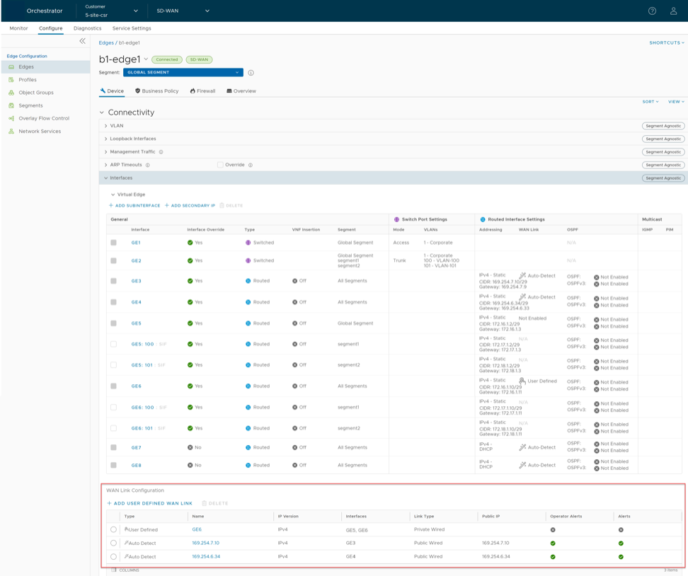
- You can select the Name of the Overlay to modify the settings. To create a new Public or Private WAN overlay, select Add User Defined WAN Link.
The Virtual Edge: new link window appears.
Figure 26. Virtual Edge: new link 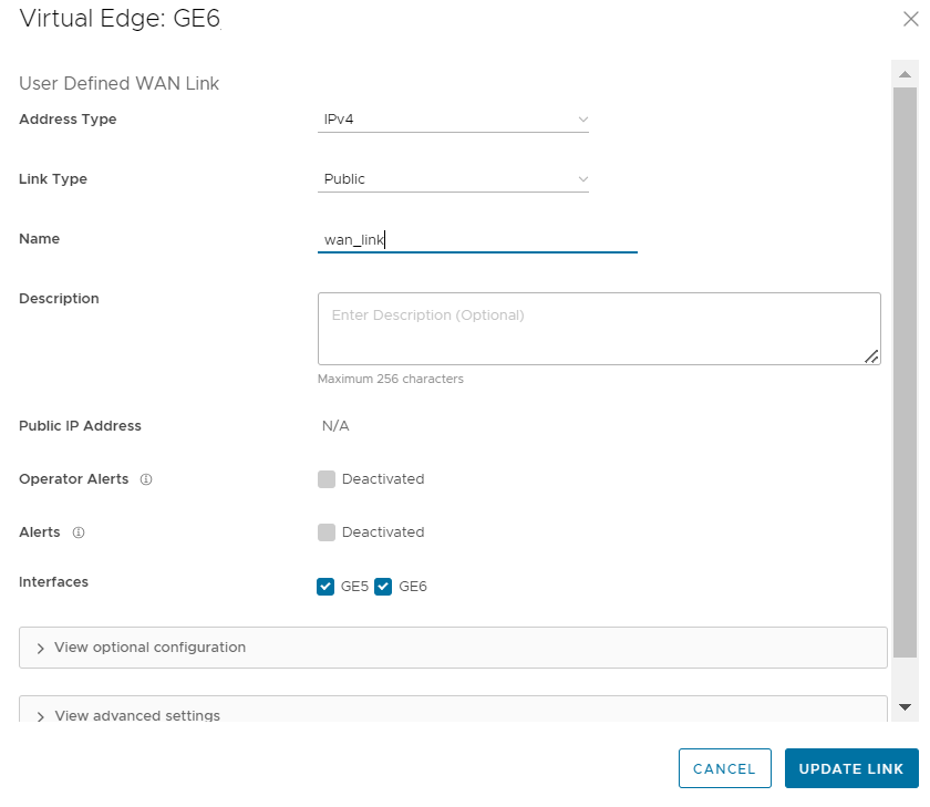
- The following image shows an example of settings for Public Overlay:
Figure 27. Settings for Public Overlay 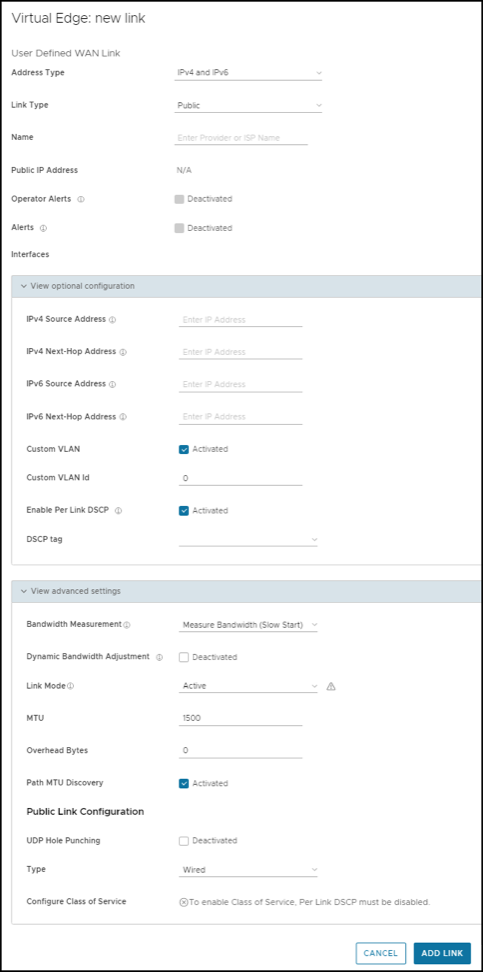
- The following image shows an example of settings for Private Overlay:
Figure 28. Settings for Private Overlay 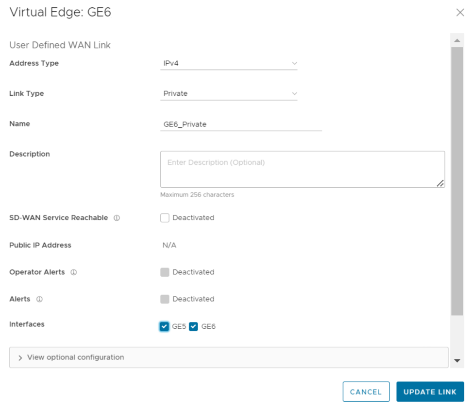
Table 23. Private Overlay Settings- Options and Descriptions Option Description Source IP Address This is the raw socket source IP address used for VCMP tunnel packets that originate from the interface to which the current overlay is attached. Source IP address does not have to be pre-configured anywhere but must be routable to and from the selected interface.
You can enter IPv4 or IPv6 address in the respective fields to establish WAN overlay with the peer.
Next-Hop IP Address Enter the next hop IP address to which the packets, which come from the raw socket source IP address specified in the Source IP Address field, are to be routed. You can enter IPv4 or IPv6 address in the respective fields.
Custom VLAN Select this check box to enable custom VLAN and enter the VLAN ID. The range is 2 to 4094. This option applies the VLAN tag to the packets originated from the Source IP Address of a VCMP tunnel from the interface to which the current overlay is attached.
Enable Per Link DSCP Select this check box to add a DSCP tag to a specific overlay link. The DSCP tag will be applied at the outer header of the VCMP packet going over this overlay link. This will provide the ability to leverage the private network underlay DSCP tag mechanism to treat each overlay uniquely via QoS setting defined at the upstream router. 802.1P Setting Select this check box to set 802.1p PCP bits on frames leaving the interface to which the current overlay is attached. This setting is only available for a specific VLAN. PCP priority values are a 3-digit binary number. The range is from 000 to 111 and default is 000. This check box is available only when the system property
session.options.enable8021PConfigurationmust be set to True. By default, this value is False.If this option is not available for you, contact the Arista Support of your operations team to enable the setting.
- The following image shows Advanced settings for a Public Overlay:
Figure 29. Advanced Settings for a Public Overlay 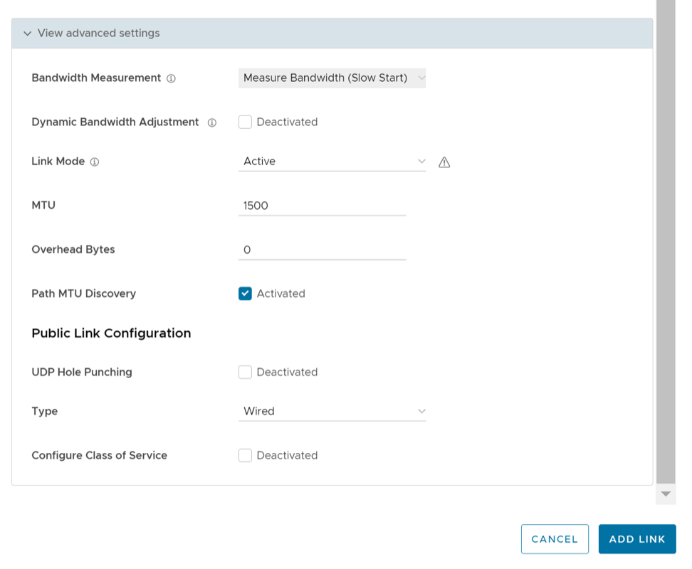
Table 26. Advanced Settings for a Public Overlay - Options and Descriptions Option Description Private Network Name If you have more than one private network and want to differentiate between them to ensure that the Edges try to tunnel only to Edges on the same private network then define a Private Network Name and attach the Overlay to it. This prevents tunneling to Edges on a different private network they cannot reach. In addition, configure the Edges in other locations on this private network to use the same private network name. For example:
Edge1 GE1 is attached to private network A. Use private network A for the private overlay attached to GE1.
Edge1 GE2 is attached to private network B. Use private network B for the private overlay attached to GE2.
Repeat the same attachment and naming for Edge2.
When you enable branch to branch or when Edge2 is a hub site:- Edge1 GE1 attempts to connect to Edge2 GE1 and not GE2.
- Edge1 GE2 attempts to connect to Edge2 GE2 and not GE1.
Configure Static SLA Forces the overlay to assume that the SLA parameters being set are the actual SLA values for the path. No dynamic measurement of packet loss, latency or jitter will be done on this overlay. The QoE report use these values for its Green/Yellow/Red coloring against thresholds. Note: Static SLA configuration is not supported from release 3.4. It is recommended not to use this option, as dynamic measurement of packet loss, latency and jitter will provide a better outcome. - The following image shows Advanced settings for a Private Overlay:
Figure 30. Advanced Settings for a Private Overlay 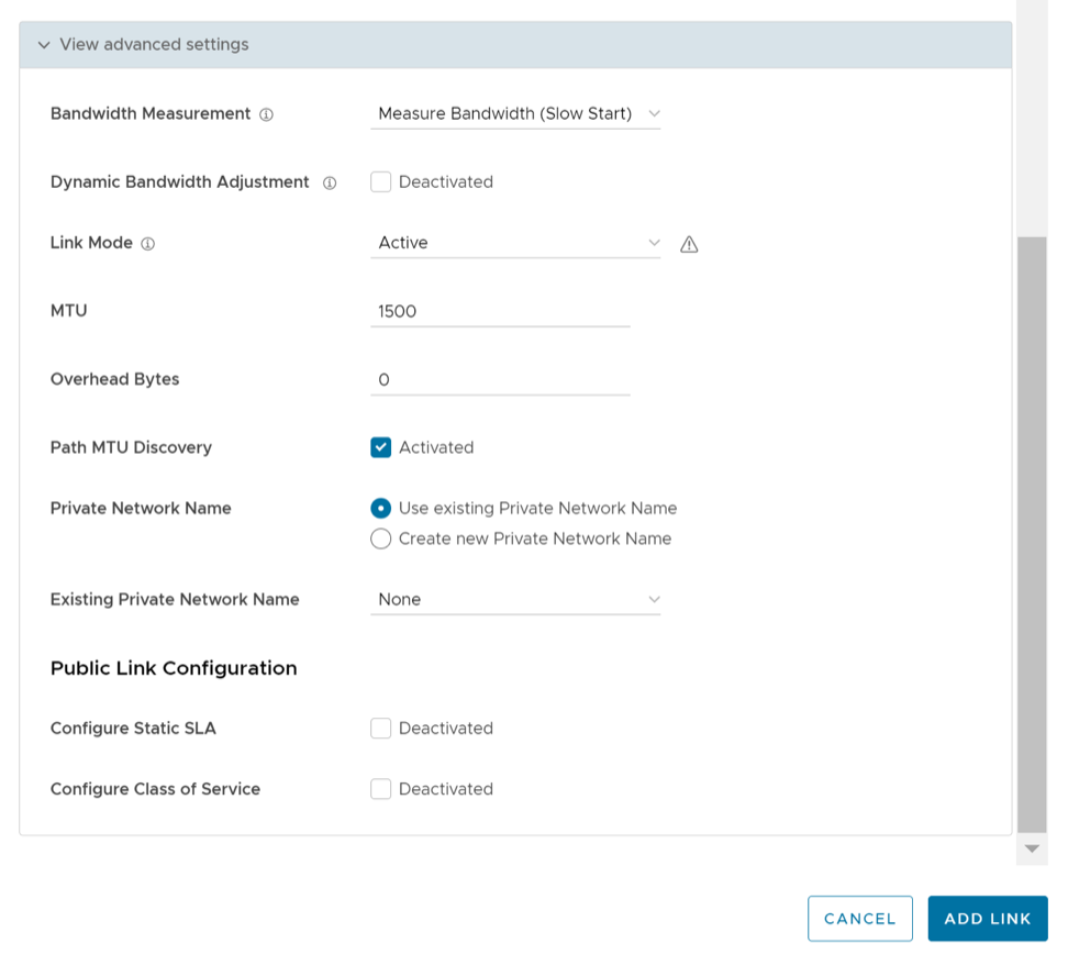
Support for DSCP Value Tag Per User Defined Overlay
With the 5.0.0 release, network administrators will have the ability to add a DSCP tag to a specific overlay link. The DSCP tag would be applied at the outer header of the VCMP packet going over the overlay link, and will leverage the private network underlay DSCP tag to treat each overlay uniquely via the QoS setting defined on the WAN underlay network.
Enable Per link DSCP Check box
Select this check box to add a DSCP tag to a specific overlay link. The DSCP tag will be applied at the outer header of the VCMP packet going over this overlay link. This will provide the ability to leverage the private network underlay DSCP tag mechanism to treat each overlay uniquely via QoS setting defined at the upstream router.
Use Case: DSCP Value Per User Defined Overlay
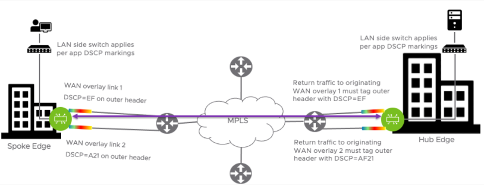
In this use case, the requirement is to apply the WAN overlay DSCP tag value configured on the WAN link to all traffic egressing from this link, for the tunnel originating Edge. The configured DSCP value should apply to the VCMP outer header so that the MPLS network can read the DSCP value and apply differentiated services to the VCMP encapsulated packet. The inner DSCP tag value, coming from the LAN side of the edge network, should be kept unmodified. Requirements on the tunnel destination side: The hub or peer edge that is receiving the tunnel creation request must respond with the same DSCP overlay tag value sent by the tunnel originator on the VCMP outer header. The hub or peer edge terminating the overlay tunnel should not modify the inner DSCP tag destined for the LAN.
In the image below, the Enterprise is using DSCP values on their underlay network to provide differentiated services based on source WAN overlay link/tunnel.
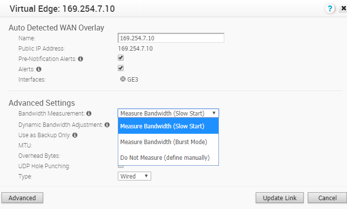
Bandwidth Measurement Modes
This section discusses how bandwidth measurement is performed on a WAN link using the VeloCloud SD-WAN service.
Once a WAN link is detected by the Edge, it first establishes DMPO (Dynamic Multi-Path Optimization) tunnels with one or more VeloCloud Gateways and performs a bandwidth test with the Primary Gateway. The bandwidth test is performed by sending a stream of bidirectional UDP traffic and measuring the received rate at each end. In addition, if the Edge is deployed as a Spoke in a Hub/Spoke topology, the Edge will also establish tunnels with the Hub Edge and perform a bandwidth test if configured to do so.
There are three modes of Bandwidth measurement are available in VeloCloud SD-WAN.
Slow Start Mode
In Slow Start mode, the Edge sends a smaller burst of UDP traffic followed by a larger burst of UDP traffic to the VeloCloud Gateway. Based on the number of packets received by the Gateway, the Gateway calculates the WAN link's speed. In Slow Start mode, the Edge sends this traffic for a fixed duration of 5 seconds. In the first 3 seconds, the Edge sends the UDP traffic at a rate of 5000 packets per second, and for the remaining 2 seconds it sends the traffic at 20000 packets per second. The packet size of this UDP traffic matches the MTU size for that WAN link.
Slow start mode is configured by default for wired links. The Edge sends a steady stream of packets for a short period of time (in case the ISP is throttling the beginning of a session) and then ramps up to a 200 Mbps stream and measures how much is received.
The reason we do this is because there are some ISPs who need packet rates to be ramped up slowly before they allow the full packet rate as part of the link SLA.
Burst Mode
In Burst mode, the Edge sends the UDP packets as single burst (A fixed, high number of packets in one burst) to the Gateway. Based on the number of packets received by the Gateway, the Gateway calculates the speed. It will start the round with 416 packets. If the Gateway response mentions that the packets were received in a very short interval, it will restart with 2000 packets. The packet size of this UDP traffic is the link MTU size.
User Defined Mode (Define Manually)
- For WAN links with greater than 900 Mbps capacity (either upload or download).
- For WAN links on Edges being used as Hubs. (This applies to hubs or any edge with a high number of tunnels.)
- On private links like MPLS, it is recommended to configure the link with a user defined value because a private link has to perform a bandwidth measurement test with every other private link in the customer's network.
- For example, in a network with multiple private links where the private peer link bandwidth values are 5 Mbps, 1 Mbps, and 500 Kbps respectively. The private link would do a bandwidth test to each of those private peer links, and may also end up measuring at the lowest peer link value. In a large network with a large number of private links, this would also be undesirable as each bandwidth measurement takes up link resources.
- If the bandwidth measurement is failing for that WAN link and no value is being registered for that link.
- Some other user preference such as deliberately limiting how much of the link capacity is used by the Edge.
Configuration
Important Notes and Limitations
- USB modems are not compatible with the slow start mode of measurement. The recommended bandwidth measurement mode for USB modem is “Burst Mode” (which is configured by default) and for wired WAN links “Slow Start” is recommended (which is configured by default).
- The Dynamic Bandwidth adjustment is recommended on links where available bandwidth can vary over time (especially wireless links). This setting will track WAN congestion and packet loss and adjust bandwidth down and up as needed. To avoid inducing congestion, bandwidth will never be adjusted to be higher than the originally measured value.
- Bandwidth is only measured to the local Gateway path unless the Edge is also a Spoke Edge in a Hub/Spoke topology. In that case bandwidth is also measured between the Spoke Edge and the Hub Edge.
- In a Hub/Spoke topology where the Hub Edge and a connected Spoke Edge have different bandwidth measurement modes configured (for example, the Hub Edge WAN link is configured with a user defined mode but the Spoke Edge's WAN link is configured with either Slow Start or Burst mode), a link measurement will be performed. However, VeloCloud SD-WAN will honor the user defined value if the measured value is greater than the user defined value. This explains why a customer can observe bandwidth measurement events on a Hub Edge even though the Hub Edge's WAN links are configured to not measure bandwidth with a user defined mode.
- When the path to the local Gateway is being measured the rest of the paths are in WAITING_FOR_LINK_BW. Once the measurement to the local Gateway path is done, the rest of the paths update their values and exchange it with their peer. This is also true when the Hub Edge is being measured by a Spoke Edge in a Hub/Spoke topology.
- The wireless links always default to Burst Mode of measurement.
- For wired links the cache is updated only on a successful measurement and this value is valid for 7 days. Bandwidth is only measured if a tunnel flaps or comes up and there is no cache or if there is a value in the cache but the last measurement was 7 days back. Wireless links have a similar behavior, but in their case the cache only needs to be older than 24 hours, and there needs to be a tunnel flap in order to trigger another bandwidth remeasurement.
- If the Automatic bandwidth measurement fails for some reason, a user can trigger a bandwidth measurement manually from the Orchestrator UI by navigating to .
- If the Automatic bandwidth measurement measures less than 90% of the originally measured(cached) value, it will not update the bandwidth. For example this will happen if you have a 1Gig link and downgrade it to a 500Mbps link, the bandwidth measurement will continue giving the old value of 1Gig. To work around this, Arista Support team will need to be engaged to delete the cached bandwidth measurement, then a new "WAN Link Bandwidth Test" can be ran from Remote Diagnostics.
- Hub Edges and Gateways process one bandwidth test at a time, to ensure accurate results. This is relevant to customers who either manually trigger multiple bandwidth measurements in a short time or make a bulk change via an API that can trigger multiple bandwidth measurements where all the tests use the same Hub Edge or Gateway.
SD-WAN Service Reachability via MPLS
An Edge with only Private MPLS links can reach the Orchestrator and Gateways located in public cloud, by using the SD-WAN Service Reachable option.
In a site with no direct public internet access, the SD-WAN Service Reachable option allows the private WAN to be used for private site-to-site VCMP tunnels and as a path to communicate with an internet hosted Arista service.
- If the Edge is a Hub, and Spoke Edges are using that Hub Edge as the internet breakout, their tunnels to the Gateway may not come up because the Hub Edge may forward those flows back out the private link.
- An Edge with this incorrect setting may appear offline in the Orchestrator. This is because it may try to use the private link to contact the Orchestrator.
MPLS-only Sites
Arista supports private WAN deployments with a hosted Arista service for customers with hybrid environments who deploy in sites with only a private WAN link.
- Enabled SD-WAN service reachability through private link
- Enabled NTP override using private NTP servers
The following image shows a Regional Hub with Internet connection and Edge with only MPLS connection.
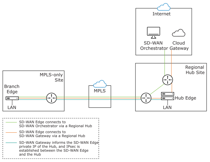
The traffic from the Edge with MPLS-only links is routed to the Orchestrator and Gateway through a Regional Hub, which is able to break out to the public cloud. SD-WAN Service Reachable option allows the Edge to remain online and manageable from the Orchestrator, and allows public internet connectivity through the Gateway irrespective of whether or not there is public link connectivity.
Dynamic Failover via MPLS
If all the public Internet links fail, you can failover critical Internet traffic to a private WAN link. The following image illustrates Resiliency of Orchestrator and Non SD-WAN Destination, Zscaler.
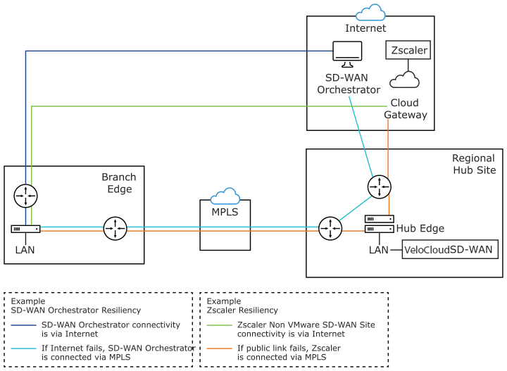
- Orchestrator Resiliency – The Orchestrator connects to the Internet. If the Internet fails, the Orchestrator will connect through MPLS. The Orchestrator connection is established using the IP Address which is advertised over MPLS. The connectivity leverages the public Internet link in the Regional Hub.
- Zscaler Resiliency – The Zscaler connectivity is established through Internet. If the public link fails, then Zscaler connects through MPLS.
Configure SD-WAN Service Reachable
- In the Interface window, select the Override check box and from the WAN Link drop-down menu, select User Defined and select Save.
Figure 35. WAN Link 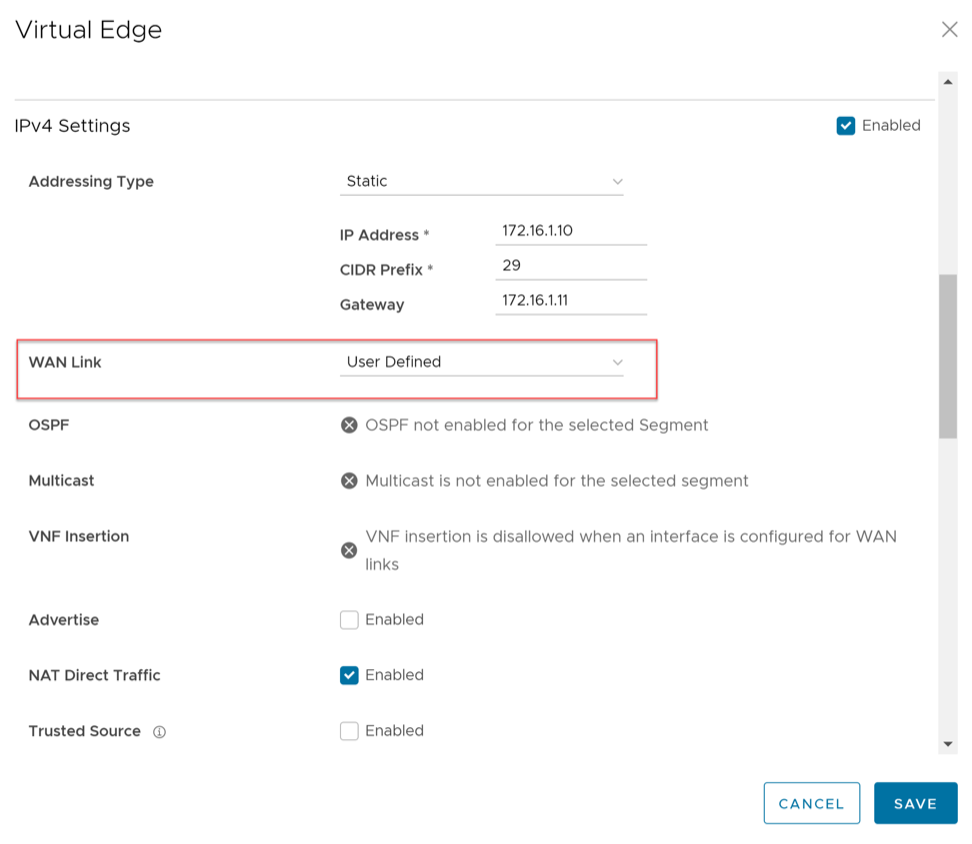 Note: The SD-WAN Service Reachable is available only for a User Defined network.
 - In the WAN Link Configuration section, select the Interface activated with User Defined WAN link. The User Defined WAN Link window appears.
Figure 36. User Defined WAN Link 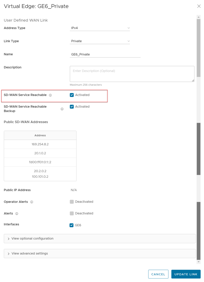
Configure Class of Service
You can manage traffic by defining Class of Service (CoS) in a public or private WAN link. You can group similar types of traffic as a class. The CoS treats each class with its level of service priority.
For each Edge consisting of public or private WAN links, you can define the CoS.
- In the WAN Link Configuration section, select Add User Defined WAN Link.
Figure 37. Add User Defined WAN Link 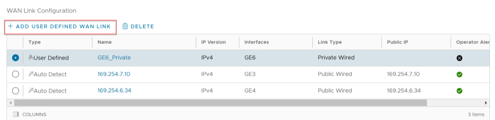
- To configure CoS for the new link, scroll down and select View advanced settings.
Figure 38. View Advanced Settings 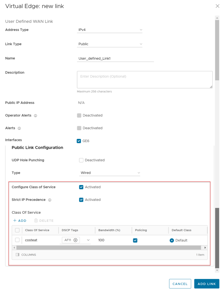
Configure Hot Standby Link
To configure a Hot Standby link on an Edge, ensure that the Edge is upgraded to software image version 4.0.0 or later.
Hot Standby link an enhanced backup link, for the WAN links of an Edge, with pre-established VCMP tunnels. When the active links are down, Hot Standby link enables immediate switchover by using the pre-established VCMP tunnels.
- In the WAN Link Configuration section, you can configure Hot Standby link mode for existing auto-detected or user-defined WAN links or you can create a new WAN link by selecting the Add User Define WAN Link and configure Hot Standby link mode. For steps on how to add a new user defined WAN link, see Configure Edge WAN Overlay Settings.
Figure 39. Add User Define WAN Link - To configure Hot Standby link mode for an existing link, select the existing WAN link and modify the settings.
Figure 40. Hot Standby Link Mode 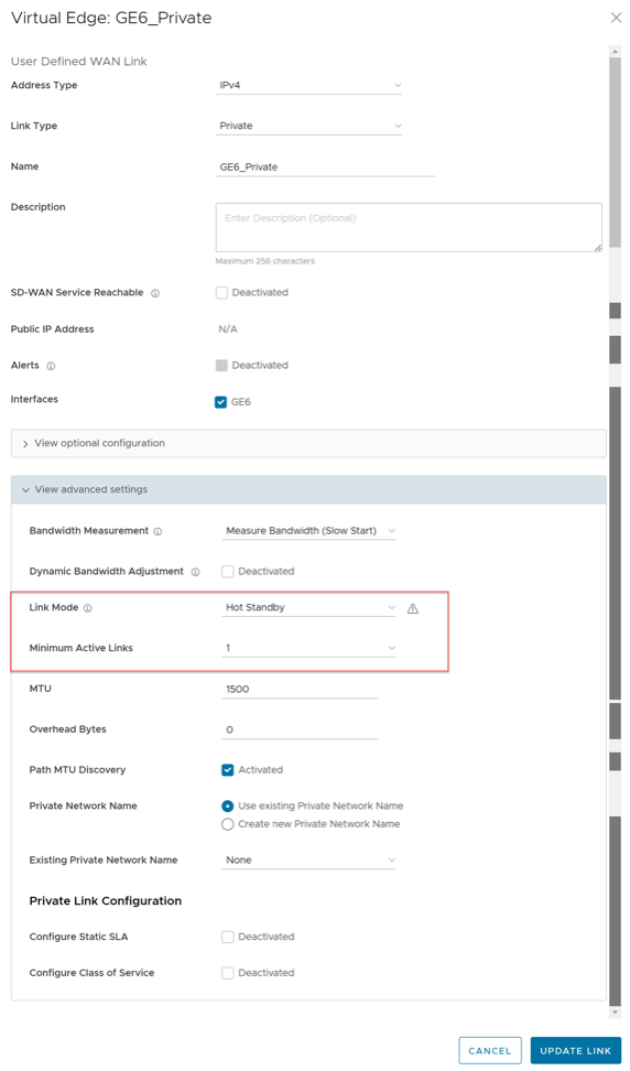
Monitor Hot Standby Links
You can monitor the Hot standby links and the corresponding status using the monitoring dashboard.
To view the status of Hot Standby links:
- Select the Paths tab and select an SD-WAN peer to view the status of the paths from the selected Edge.
Figure 41. Paths 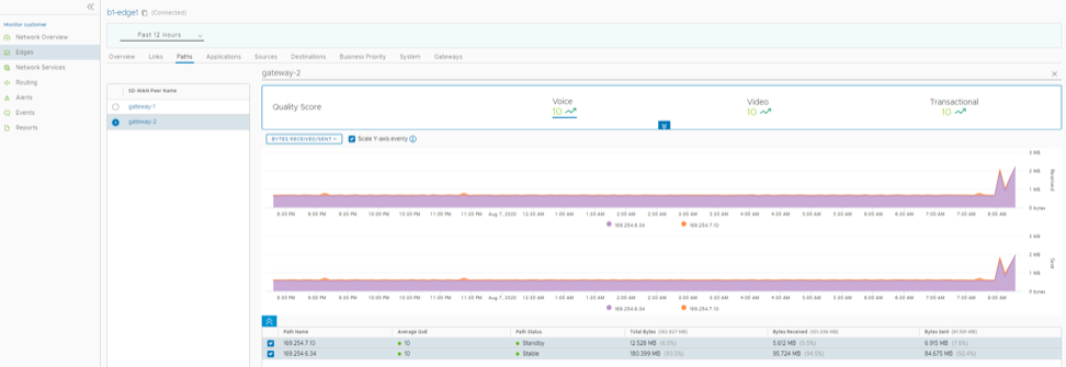
Configure DHCPv6 Prefix Delegation for Edges
DHCPv6 Prefix Delegation feature allows packet exchange between a DHCP Client and a DHCP Server. The Edge requests the server to provide prefixes over the WAN interfaces to delegate to clients on the LAN side. The server provides a prefix to the Edge in response. The Edge then configures an IP address on the LAN interface using this delegated prefix. The Edge starts sending out router advertisements with this prefix.
- In the SD-WAN service of the Enterprise portal, select . The Edges page displays the existing Edges.
- Select the link to an Edge or select the View link in the Device column of the Edge. The configuration options for the selected Edge display on the Device tab.
- DHCPv6 Prefix Delegation can be configured on WAN, LAN, and VLAN interfaces. See the following sections for additional details:
- DHCPv6 Prefix Delegation on a WAN Interface
Note: For a WAN interface, the Enable WAN Link option must be selected.
- On the Edge Device settings page, go to the Connectivity category, and then expand Interfaces.
- The Interfaces section displays the different types of Interfaces available for the selected Edge. Select the link to a Routed WAN interface.
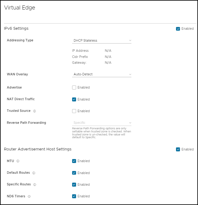
- On the Routed Interface Settings screen, navigate to IPv6 Settings.
Figure 42. Configuring IPv6 Settings 
- Activate the DHCPv6 Client Prefix Delegation feature by selecting the Enabled check box.
- You can either select a pre-defined tag from the drop-down menu or create a new tag by selecting the New Tag option. You can also define tags on the Network Services screen. For additional information, see Configure Prefix Delegation Tags.
Note: Each WAN interface must have a unique tag.
- Select Save.
- DHCPv6 Prefix Delegation on a LAN Interface
Note: For a LAN interface, do not select the Enable WAN Link option.
- On the Edge Device settings page, go to the Connectivity category, and then expand Interfaces.
- The Interfaces section displays the different types of Interfaces available for the selected Edge. Select the link to a Routed LAN interface.
- On the Routed Interface settings screen, navigate to IPv6 Settings.
Figure 43. IPv6 Settings 
- To configure Prefix Delegation for a LAN interface, you must select the Addressing Type as DHCPv6 Prefix Delegation from the drop-down menu.
- The following additional options appear on the screen:
Table 27. Addressing Type option Descriptions Option Description Prefix Length This field auto-populates. The value displays as 64. This indicates a configuration of a 64 bits netmask for the interface address. Interface Address Enter a valid interface address. The new address is formed by combining the prefix provided by the server and the interface address that is configured. If 'n' bits prefix is received from the server, then the first 'n' bits of the interface address overwrites to form a new address. Tag Select the tag from the drop-down menu to associate the configured interface address with the corresponding WAN interface. Note: The same tag can be used by multiple LAN interfaces.Warning: Ensure that the same combination of Interface Address and Tag is not used on any two LAN/VLAN interfaces on the same Edge. This could lead to duplicate addresses getting assigned on those interfaces. - Select Save. For information on the other settings on this screen, see Configure Interface Settings for Edges.
- DHCPv6 Prefix Delegation on a VLAN Interface
- On the Edge Device settings page, go to the Connectivity category, and then expand VLAN.
- Select on a VLAN interface.
- In the Edit VLAN dialog, navigate to the IPv6 Settings section.
Figure 44. Navigating to IPv6 Settings 
- To configure Prefix Delegation for a VLAN interface, you must select the Addressing Type as DHCPv6 Prefix Delegation from the drop-down menu.
- Select a tag from the drop-down menu.
- Enter a valid interface address.
- Select Done.
- DHCPv6 Prefix Delegation on a WAN Interface
Global IPv6 Settings for Edges
For IPv6 addresses, you can activate some of the configuration settings globally.
To activate global settings for IPv6 at the Edge level:
- Under the Connectivity category, select Global IPv6 and select the Override check box.
Figure 45. Global IPv6 Settings for Edges 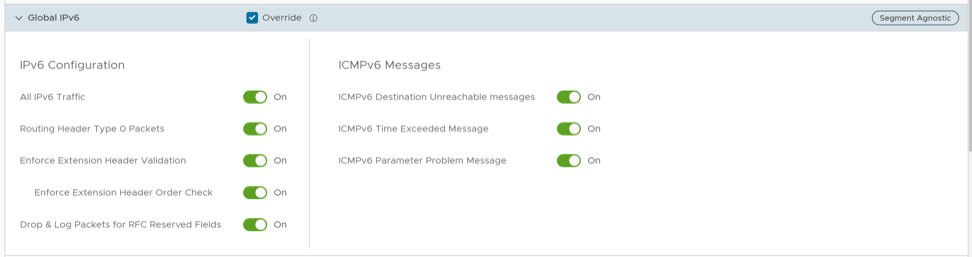
Configure Wi-Fi Radio Overrides
At the Edge level, you can override the Wi-Fi Radio settings specified in the Profile, by selecting the Override check box. Based on the Edge model and the country configured for the Edge, Wi-Fi Radio settings allow you to select a radio band and channel supported for the Edge.
Before configuring the Wi-Fi radio band and channel for the Edge, it is important to set the correct country of operation for the Wi-Fi radio, to conform to local requirements for Wi-Fi transmission. The address is populated automatically after the Edge is activated; however, you can override the address manually, if needed. If you want to change the location of the Edge, go to the Contact & Location section of the Edge Overview configuration page and select Edit Location to set the Edge location, and then select Save Changes.
To override the Wi-Fi Radio settings at the Edge level, perform the following steps:
- Under the Connectivity category, go to the Wi-Fi Radio area and select the Override check box.
Figure 46. Configure Wi-Fi Radio Overrides 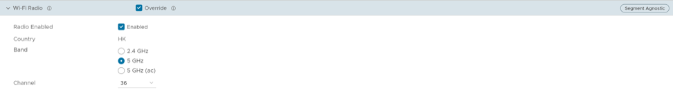
- Edge 710 supports dual-radio models. In this case, the settings from the common Profile Radio are automatically inherited, so that only one radio is activated. But if these settings are overridden, you have an option to activate both radios to simultaneously transmit on 2.4 and 5 GHz.
Figure 47. Override Wi-Fi Radio Settings for Edge 710 Model 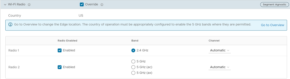 Note:
Note:- Edge 710 has a Wi-Fi 6 card (802.11ax) that has 2 radios; one that can transmit only in the 2.4 GHz band, and one that can transmit only in 5 GHz band. Each band is independently capable of being set up as 802.11n, ac or ax. Typically, you must activate ac and ax on the 5GHz band.
- Dual-radio models independently use both, 2.4 GHz and 5 GHz bands. However, if the 5 GHz band is selected in an unsupported country, it is deactivated, and the 2.4 GHz band is activated by default.
- Single-radio models default to either 2.4 GHz or 5GHz. In case where both bands are selected, the radio transmits in the 5 GHz band, if it is in a supported country, else it is forced to use the 2.4 GHz band, irrespective of the Profile settings.
- For Edge 710 5G with unsupported country, the Channel is always set to Automatic. But for Edge 710 5G with a supported country, you can select a Channel value from the drop-down menu.
Configure Automatic SIM Switchover
- You must insert SIM cards in both the SIM slots on the Edge.
- This feature can be activated only on a standalone Edge where High Availability is deactivated. An error is displayed on the Orchestrator if you try to activate both, High Availability and Automatic Switchover features.
- Navigate to , and make sure that the IP Type, L2 Settings, and WAN Overlay settings are same for both Cell1 and Cell2. Other parameters like SIM PIN, Network, and APN need not be same.
- Both Cell1 and Cell2 interfaces must be activated before activating the Automatic Switchover feature. For additional information, see Configure Interface Settings for Edges.
This feature allows you to automate the process of LTE SIM switching in case of primary LTE connection failure. You can configure the Edge to automatically detect the primary LTE link failure and thereby initiate the process of establishing the secondary LTE link. When the Automatic Switchover feature is activated, and for some reason, the secondary LTE link is also down, the Edge tries to establish the connection with the primary link again. This process continues until the Edge detects an active LTE link. Also, if automatic switchover is in progress, manual switchover cannot be performed on the Edge.
To access this feature, follow the below steps:
- In the Connectivity category, expand Automatic Switchover. The Configure Automatic SIM Switchover screen appears.
Figure 48. Configure Automatic SIM Switchover 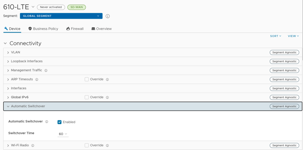
- To monitor the Edge Switchover status, go to , and then select the link to your Edge. The Overview tab is displayed by default.
Figure 49. Monitor Edge Switchover 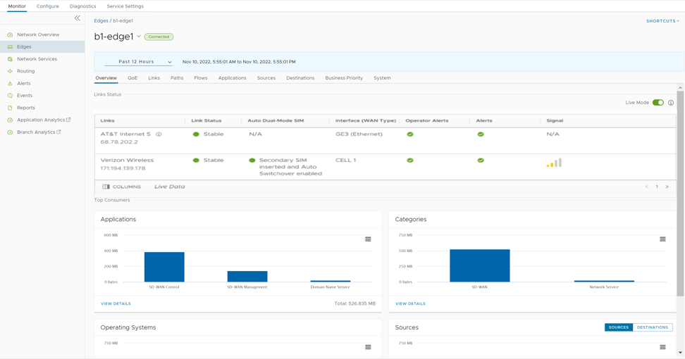
- The Auto Dual-Mode SIM column displays the status of the Edge with respect to the Automatic Switchover feature configured on that Edge, and is applicable to Edge 610-LTE and Edge 710 5G. See the table below for the color code details:
Table 30. Color Codes of Automatic Switchover Configured Edge Status Color Status Green Indicates that the Secondary SIM is inserted and the Automatic Switchover feature is activated. Amber / Orange Indicates that the Secondary SIM is inserted and the Automatic Switchover feature is deactivated. Purple Indicates that the Secondary SIM is not inserted and the Automatic Switchover feature is activated. Red Indicates that the Secondary SIM is not inserted and the Automatic Switchover feature is deactivated. - The Signal column displays the signal strength of the Edge. This is indicated by the number of bars, which vary depending on the signal strength. Below are the details:
Table 31. Edge Signal Strength Indicators Signal Strength (dB) Number of Bars -10 to -85 4 -86 to -102 3 -103 to -110 2 -111 to -120 1 -121 to -999 0 For additional information, see Monitor Edges.
The Switchover status can also be viewed on the page. The following two events are displayed on the screen when the Automatic Switchover feature is activated.
For additional information, see Monitor Events.Table 32. Automatic Switchover Events Descriptions Event Description EDGE_AUTO_SIM_SWITCH This event is triggered in the following scenarios when the Automatic Switchover feature is activated or deactivated: - The Automatic Switchover feature fails to get activated after the Orchestrator sends the configuration to the Edge.
- During the switchover process, when there is at least one active WAN link on the Edge.
EDGE_CELL_SWITCHOVER This event is triggered after the cell switchover process, irrespective of whether the process was successful or not. - The Auto Dual-Mode SIM column displays the status of the Edge with respect to the Automatic Switchover feature configured on that Edge, and is applicable to Edge 610-LTE and Edge 710 5G. See the table below for the color code details:
Configure Common Criteria Firewall Settings for Edges
The Common Criteria (CC) Firewall settings are inherited from the Profile associated with the Edge and can be reviewed in the Edge Device tab. At the Edge level, you can choose to override the CC Firewall settings for an Edge.
To configure the CC Firewall settings at the Edge level, perform the following steps:
- The Device tab displays the configuration options for the selected Edge.
Figure 50. Configure Common Criteria Firewall Settings for Edges 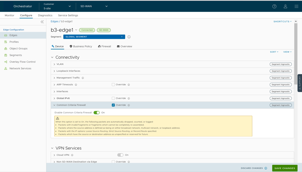
Configure Cloud VPN and Tunnel Parameters for Edges
The Edge Cloud VPN settings are inherited from the Profile associated with the Edge and can be reviewed in the Edge Device tab. At the Edge level, you can override these settings inherited from a Profile and configure tunnel parameters.
- Select the Override check box to override the Non SD-WAN Destination settings inherited from the Profile as needed.
Note: Any configuration changes to Branch to Non SD-WAN Destination via Gateway settings can be made only in the associated Profile level.
Figure 51. Configure Cloud VPN and Tunnel Parameters for Edges 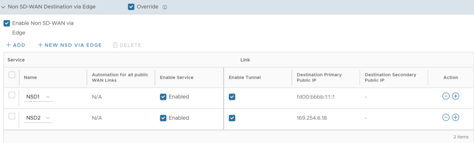
- Under the Action column, select + to add tunnels. The Add Tunnel pop-up window appears.
Figure 52. Add Tunnel 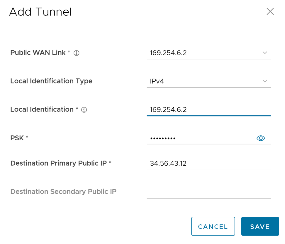
Configure Cloud Security Services for Edges
When you have assigned a profile to an Edge, the Edge automatically inherits the cloud security service (CSS) and attributes configured in the profile. You can override the settings to select a different cloud security provider or modify the attributes for each Edge.
To override the CSS configuration for a specific Edge, perform the following steps:
Manual Zscaler CSS Provider Configuration for Edges
At the Edge level, for a selected manual Zscaler CSS provider, you can override the settings inherited from the profile and can configure additional parameters manually based on the tunneling protocol selected for tunnel establishment.
If you choose to configure an IPsec tunnel manually, apart from the inherited attributes, you must configure a Fully Qualified Domain Name (FQDN) and Pre-Shared Key (PSK) for the IPsec session.
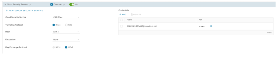
If you choose to configure a GRE tunnel manually, then you must configure GRE tunnel parameters manually for the selected WAN interface to be used as source by the GRE tunnel, by following the steps below.
- Under GRE Tunnels, select +Add.
Figure 54. Add GRE Tunnels 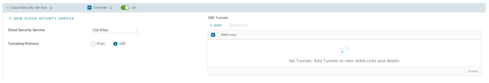
- In the Configure Tunnel window appears, configure the following GRE tunnel parameters, and select Update.
Figure 55. Configure Tunnel 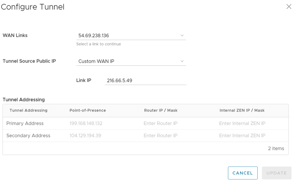
Table 34. Tunnel Configuration Option Descriptions Option Description WAN Links Select the WAN interface to be used as source by the GRE tunnel. Tunnel Source Public IP Choose the IP address to be used as a public IP address by the Tunnel. You can either choose the WAN Link IP or Custom WAN IP. If you choose Custom WAN IP, enter the IP address to be used as public IP. Source public IPs must be different for each segment when Cloud Security Service (CSS) is configured on multiple segments. Primary Point-of-Presence Enter the primary Public IP address of the Zscaler Datacenter. Secondary Point-of-Presence Enter the secondary Public IP address of the Zscaler Datacenter. Primary Router IP/Mask Enter the primary IP address of Router. Secondary Router IP/Mask Enter the secondary IP address of Router. Primary Internal ZEN IP/Mask Enter the primary IP address of Internal Zscaler Public Service Edge. Secondary Internal ZEN IP/Mask Enter the secondary IP address of Internal Zscaler Public Service Edge. Note:- The Router IP/Mask and ZEN IP/Mask are provided by Zscaler.
- Only one Zscaler cloud and domain are supported per Enterprise.
- Only one CSS with GRE is allowed per Edge. An Edge cannot have more than one segment with Zscaler GRE automation enabled.
Scale Limitations:- GRE-WAN: Edge supports maximum of 4 public WAN links for a Non SD-WAN Destination (NSD) and on each link, it can have up to 2 tunnels (primary/secondary) per NSD. So, for each NSD, you can have maximum of 8 tunnels and 8 BGP connections from one Edge.
- GRE-LAN: Edge supports 1 link to Transit Gateway (TGW), and it can have up to 2 tunnels (primary/secondary) per TGW. So, for each TGW, you can have maximum of 2 tunnels and 4 BGP connections from one Edge (2 BGP sessions per tunnel).
Automated Zscaler CSS Provider Configuration for Edges
- IPsec/GRE Tunnel Automation
- Zscaler Location/Sub-Location Configuration
IPsec/GRE Tunnel Automation
IPsec/GRE tunnel automation can be configured for each Edge segment. Perform the following steps to establish automatic tunnels from an Edge.
- From the Cloud Security Service drop-down menu, select an automated CSS provider and select Save Changes.
Figure 56. Override Automated Zscaler CSS Provider 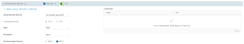
The automation will create a tunnel in the segment for each Edge's public WAN link with a valid IPv4 address. In a multi-WAN link deployment, only one of the WAN Links will be utilized for sending user data packets. The Edge chooses the WAN link with the best Quality of Service (QoS) score using bandwidth, jitter, loss, and latency as criteria. Location is automatically created after a tunnel is established. You can view the details of tunnel establishment and WAN links in the Cloud Security Service section
Note: After automatic tunnel establishment, changing to another CSS provider from an Automated Zscaler service provider is not allowed on a Segment. For the selected Edge on a segment, you must explicitly deactivate Cloud Security service and then reactivate CSS if you want to change to a new CSS provider from an Automated Zscaler service provider.
Zscaler Location/Sub-Location Configuration
After you have established automatic IPsec/GRE tunnel for an Edge segment, Location is automatically created and appears under the Zscaler section of the Edge Device page.
- You check that the tunnel is established from the selected Edge and Location is automatically created. You will not be allowed to create a Sub-location if the VPN credentials or GRE options are not set up for the Edge. Before configuring Sub-locations, ensure you understand about Sub location and their limitations. See https://help.zscaler.com/zia/understanding-sublocations.
- You select the same Cloud Subscription that you used to create the Automatic CSS.
- In the SD-WAN service of the Enterprise portal, select .
- Select an Edge and select the icon under the Device column. The Device Settings page for the selected Edge appears.
- Go to the Zscaler section and turn on the toggle button.
Figure 57. Override Zscaler Settings 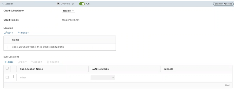
- From the Cloud Subscription drop-down menu, select the same Cloud Subscription that you used to create the Automatic CSS. The Cloud Name associated to the selected Cloud Subscription automatically appears.
Note:
- Cloud Subscription must have same Cloud name and Domain name as CSS.
- If you want to change provider for "Cloud Subscription", you must first remove the "Location" by deactivating CSS and Zscaler, and then perform the creation steps with the new provider.
In the Location table, selecting View under the Action Details column displays the actual values for the configuration fetched from Zscaler, if present. If you want to configure the Gateway options and Bandwidth controls for the Location, select the Edit button under Gateway Options.
- To create a Sub-location, in the Sub-Locations table, select the '+' icon under the Action column.
- In the Sub-Location Name text box, enter a unique name for the Sub-location. The Sub location name should be unique across all segments for the Edge. The name can contain alphanumeric with a maximum word length of 32 characters.
- From the LAN Networks drop-down menu, select a VLAN configured for the Edge. The Subnet for the selected LAN network will be populated automatically.
Note: For a selected Edge, Sub-locations should not have overlapping Subnet IPs.
- Device Settings Save Changes.
Figure 58. Create Sub-locations 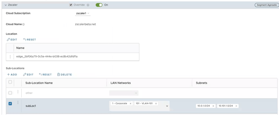 Note: After you create at least one Sub-location in the Orchestrator, an “Other” Sub location is automatically created in the Zscaler side, and it appears in the Orchestrator UI. You can also configure the “Other” Sub-location’s Gateway options by selecting the Edit button under Gateway Options in the Sub-Locations table.
 - After creating a Sub-location, you can update the Sub-location configurations from the same Orchestrator page. Once you select Save Changes, the Sub-location configurations on the Zscaler side will be updated automatically.
- To delete a Sub-location, select the '-' icon under the Action column.
Note: When the last Sub-location is deleted from the table, the "other" Sub-location also gets deleted automatically.
Configure Zscaler Gateway Options and Bandwidth Control
To configure Gateway options and Bandwidth controls for the Location and Sub-location, select the Edit button under Gateway Options, in the respective table.
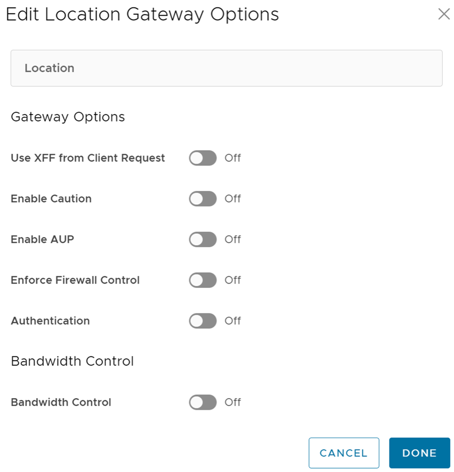
Configure the Gateway options and Bandwidth controls for the Location and Sub-location, as needed, and select Save Changes.
| Option | Description |
|---|---|
| Gateway Options for Location/Sub-Location | |
| Use XFF from Client Request | Enable this option if the location uses proxy chaining to forward traffic to the Zscaler service, and you want the service to discover the client IP address from the X-Forwarded-For (XFF) headers that your on premises proxy server inserts in outbound HTTP requests. The XFF header identifies the client IP address, which can be leveraged by the service to identify the client’s sub location. Using the XFF headers, the service can apply the appropriate sub location policy to the transaction, and if Enable IP Surrogate is turned on for the location or sub-location, the appropriate user policy is applied to the transaction. When the service forwards the traffic to its destination, it will remove the original XFF header and replace it with an XFF header that contains the IP address of the client gateway (the organization’s public IP address), ensuring that an organization's internal IP addresses are never exposed to externally.
Note: This Gateway option is only configurable for Parent location.
|
| Enable Caution | If you have not enabled Authentication, you can enable this feature to display a caution notification to unauthenticated users. |
| Enable AUP | If you have not enabled Authentication, you can enable this feature to display an Acceptable Use Policy (AUP) for unauthenticated traffic and require users to accept it. If you enable this feature:
|
| Enforce Firewall Control | Select to enable the service's firewall control.
Note: Before enabling this option, user must ensure if its Zscaler account has subscription for "Firewall Basic".
|
| Enable IPS Control | If you have enabled Enforce Firewall Control, select this to enable the service's IPS controls.
Note: Before enabling this option, user must ensure if its Zscaler account has subscription for "Firewall Basic" and "Firewall Cloud IPS".
|
| Authentication | Enable to require users from the Location or Sub-location to authenticate to the service. |
| IP Surrogate | If you enabled Authentication, select this option if you want to map users to device IP addresses. |
| Idle Time for Dissociation | If you enabled IP Surrogate, specify how long after a completed transaction, the service retains the IP address-to-user mapping. You can specify the Idle Time for Dissociation in Mins (default), or Hours, or Days.
|
| Surrogate IP for Known Browsers | Enable to use the existing IP address-to-user mapping (acquired from the surrogate IP) to authenticate users sending traffic from known browsers. |
| Refresh Time for re-validation of Surrogacy | If you enabled Surrogate IP for Known Browsers, specify the length of time that the Zscaler service can use IP address-to-user mapping for authenticating users sending traffic from known browsers. After the defined period of time elapses, the service will refresh and revalidate the existing IP-to-user mapping so that it can continue to use the mapping for authenticating users on browsers. You can specify the Refresh Time for re validation of Surrogacy in minutes (default), or hours, or days.
|
| Bandwidth Control Options for Location | |
| Bandwidth Control | Enable to enforce bandwidth controls for the location. If enabled, specify the maximum bandwidth limits for Download (Mbps) and Upload (Mbps). All sub locations will share the bandwidth limits assigned to this location. |
| Download | If you enabled Bandwidth Control, specify the maximum bandwidth limits for Download in Mbps. The allowable range is from 0.1 through 99999. |
| Upload | If you enabled Bandwidth Control, specify the maximum bandwidth limits for Upload in Mbps. The allowable range is from 0.1 through 99999. |
Bandwidth Control Options for Sub-Location (if Bandwidth Control is enabled on Parent Location)
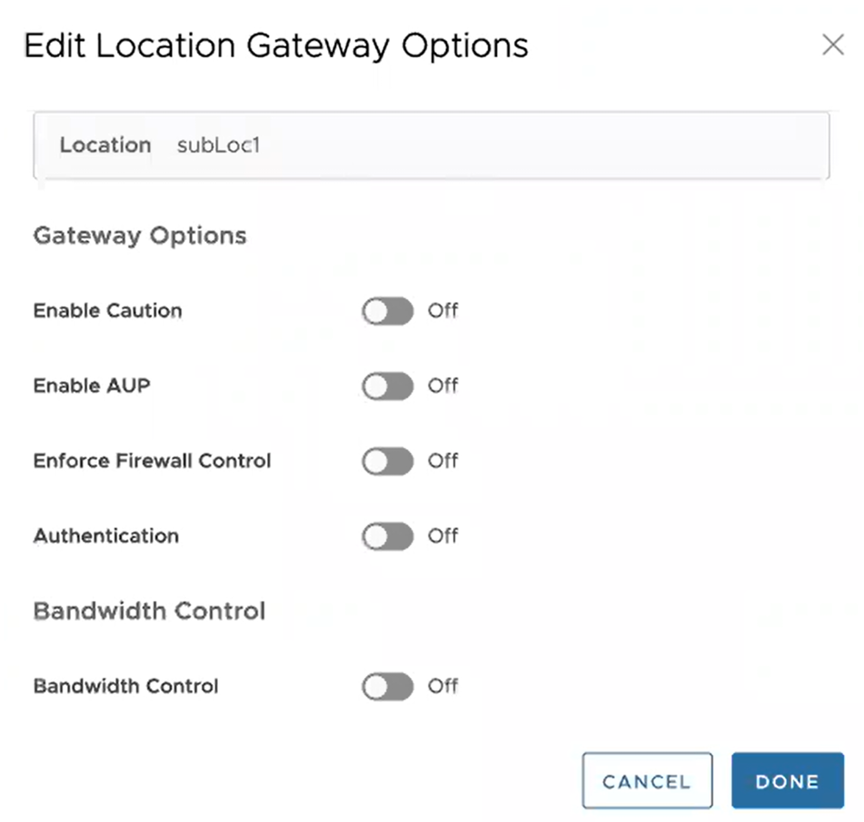
Note: The following bandwidth control options are configurable for sub-location only if you have bandwidth control enabled on the parent location. If the bandwidth control is not enabled on the parent location, then the bandwidth control options for sub-location are the same as location (Bandwidth Control, Download, Upload).
|
|
| Use Location Bandwidth | If you have bandwidth control enabled on the parent location, select this option to enable bandwidth control on the sub-location and use the download and upload maximum bandwidth limits as specified for the parent location. |
| Override | Select this option to enable bandwidth control on the sub-location and then specify the maximum bandwidth limits for Download (Mbps) and Upload (Mbps). This bandwidth is dedicated to the sub-location and not shared with others. |
| Disabled | Select this option to exempt the traffic from any Bandwidth Management policies. Sub-location with this option can only use up to a maximum of available shared bandwidth at any given time. |
Limitations
- In 4.5.0 release, when a Sub-location is created, Orchestrator automatically saves the "Other" Sub location. In earlier version of Orchestrator, the Zscaler "Other" Sub-location was not saved in Orchestrator. After upgrading Orchestrator to 4.5.0 release, the "Other" Sub-location will be imported automatically only after a new normal (non-Other) Sub-location is created using automation.
- Zscaler Sub-locations cannot have overlapping IP addresses (subnet IP ranges). Attempting to edit (add, update, or delete) multiple Sub-locations with conflicting IP addresses may cause the automation to fail.
- Users cannot update the bandwidth of Location and Sub-location at the same time.
- Sub-locations support Use Location Bandwidth option for bandwidth control when its Parent Location bandwidth control is enabled. When user turns off the Location bandwidth control on a Parent Location, the Orchestrator does not check or update the Sub-location bandwidth control option proactively.
Configure Zscaler Settings for Edges
Describes how to configure Zscaler at the Edge level. You can configure the Zscaler settings for an Edge from the Zscaler section available under the VPN Services category in the Device tab.
Before you configure Zscaler, you must have Zscaler cloud subscription. For steps on how to create cloud subscription of type Zscaler, Configure API Credentials.
To configure Zscaler at the Edge level, perform the following steps:
- The configuration options for the selected Edge are displayed in the Device tab.
Figure 61. Configure Zscaler Settings for Edges 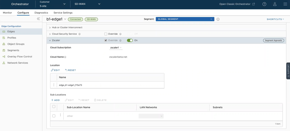
- To edit location Gateway options. select the Edit button under the Location section. The Edit Location Gateway Options dialog box appears.
Figure 62. Edit Location Gateway Options Window 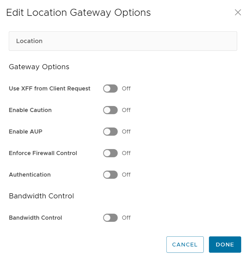
- In the Sub-Locations section, you can perform the following:
- To add sub-locations, select the +ADD button and specify sub-location name, LAN networks, and Subnets.
In prior Orchestrator versions, for the Zscaler sub-location configuration, the Subnets field that takes in subnets ignores the user input if the subnet being added is not directly connected to the Edge device, and users could not modify these subnets using the Orchestrator UI. This limitation presented a challenge for a branch offices where the LAN-side subnets were one hop away due to the presence of a layer 3 switch between the Edge and LAN devices. Release 6.0.0 allows users to add both direct and non-direct subnets.
Figure 63. Add Sub-locations 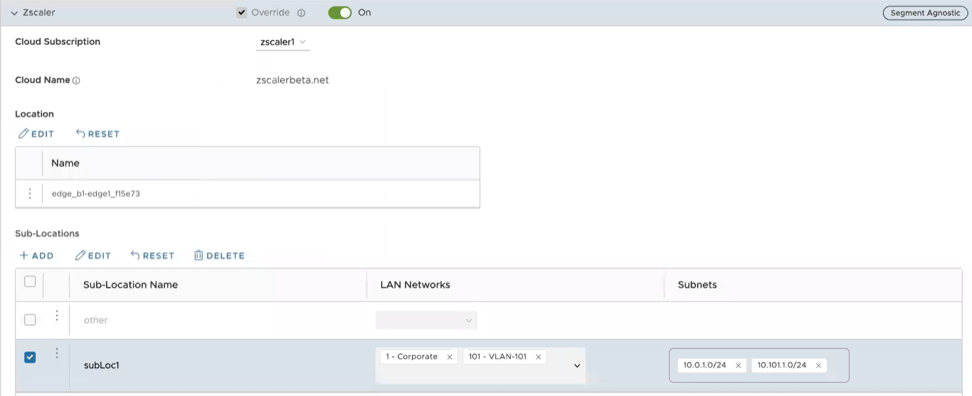
- To edit Gateway options and Bandwidth control settings for selected Sub-Locations, select the Edit button.
Figure 64. Edit Location Gateway Options 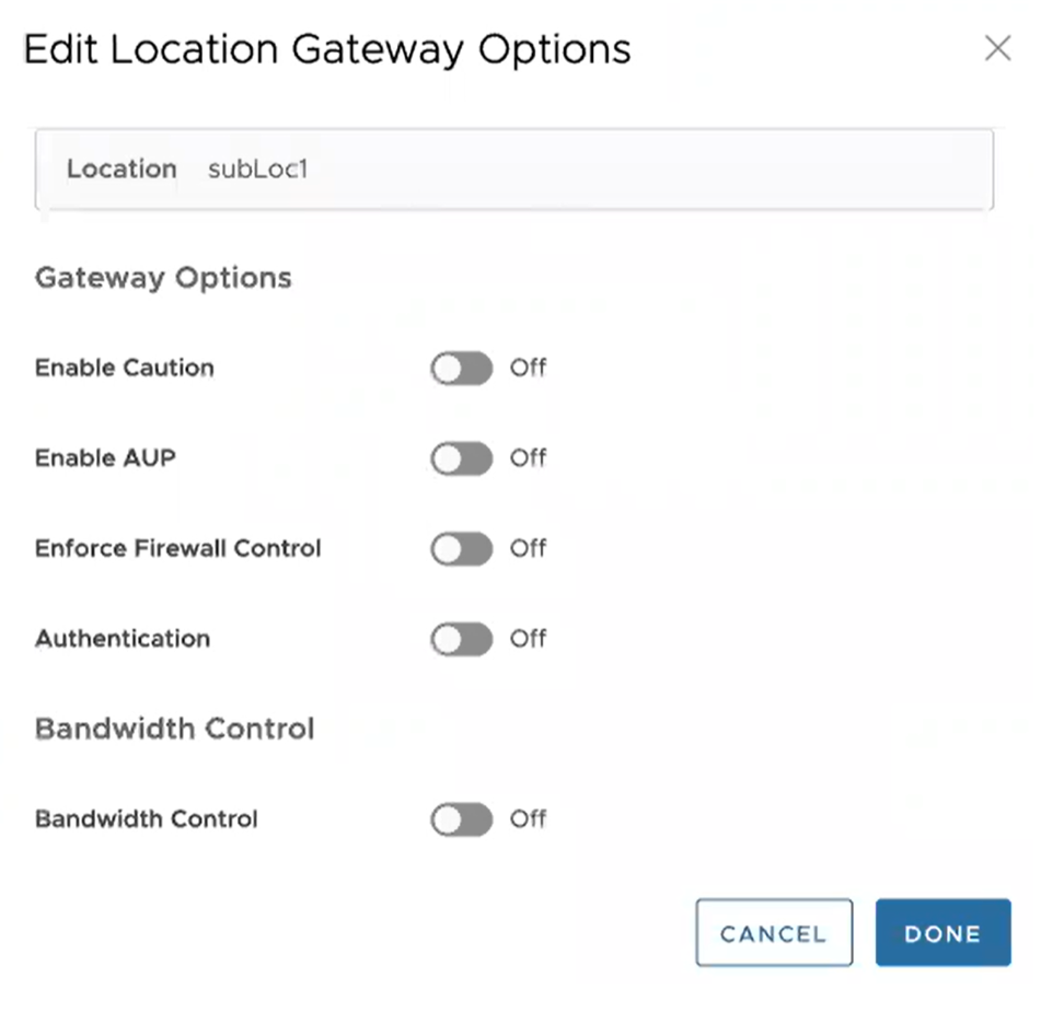
- To reset Zscaler Sub-Location gateway options to default, select Reset.
- To delete sub-locations, select the sub-locations that you want to delete and select the Delete button.
- To add sub-locations, select the +ADD button and specify sub-location name, LAN networks, and Subnets.
Configure Multicast Settings for Edges
Multicast provides an efficient way to send data to an interested set of receivers to only one copy of data from the source, by letting the intermediate multicast-routers in the network replicate packets to reach multiple receivers based on a group subscription.
The Multicast settings are applied to all the Edges associated with the Profile. You can choose to override the Multicast settings for an Edge:
- Scroll down to the Routing & NAT category and expand the Multicast area.
Figure 65. Configure Multicast Settings for Edges 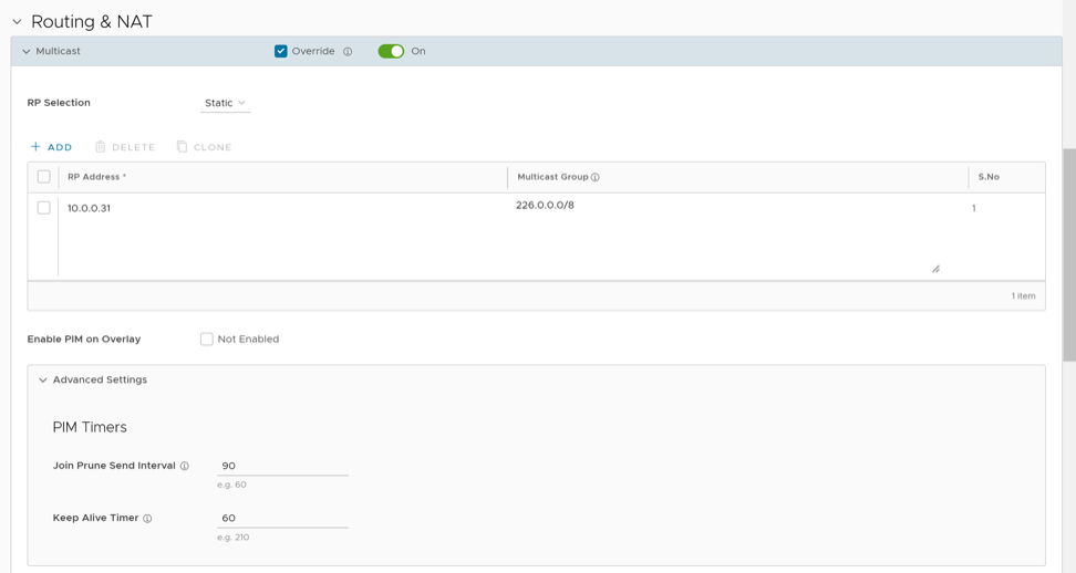
Configure BFD for Edges
VeloCloud SD-WAN allows to configure BFD sessions to detect route failures between two connected entities. Once you have configured BFD rules for a Profile, the rules are automatically applied to the Edges that are associated with the profile. Optionally, you can override the inherited settings at the Edge level.
To override the configuration for a specific Edge:
- Select the Override check box to modify the BFD configuration settings for the selected Edge.
Figure 66. Configure BFD for Edges 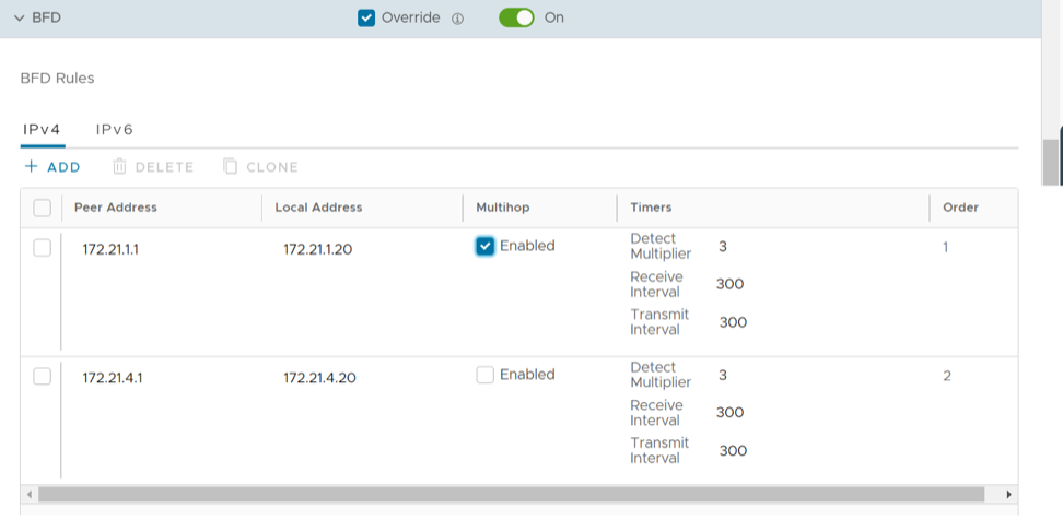
LAN-side NAT Rules at Edge Level
LAN-Side NAT (Network Address Translation) Rules allow you to NAT IP addresses in an unadvertised subnet to IP addresses in an advertised subnet. For both the Profile and Edge levels, within the Device Settings configuration, LAN-side NAT Rules has been introduced for the 3.3.2 release and as an extension, LAN side NAT based on source and destination, same packet source and destination NAT support have been introduced for the 3.4 release.
By default, the LAN-Side NAT Rules are inherited by the Edges associated with the Profile. To override the NAT-Side NAT Rules at the Edge level, perform the steps below.
0.0.0.0/0.- In the SD-WAN Service of the Enterprise portal, go to .
- Select the appropriate Edge by selecting the check box next to the Edge Name.
- If not already selected, select the Device tab link.
- Scroll down to the Routing & NAT.
- Open the LAN-Side NAT Rules area.
- Select the Override check box to make changes to the LAN-Side NAT Rules.
- In the LAN-Side NAT Rules area, complete the following for the NAT Source or Destination section: (See the table below for a description of the fields in the steps below).
- Enter an address for the Inside Address.
- Enter an address for the Outside Addressx.
- Enter the Source Route.
- Enter the Destination Route.
- Type a description for the rule in the Description textbox (optional).
Figure 67. Lan-Side NAT Rules 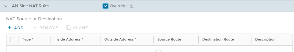
Table 36. LAN-side NAT Rule Types Descriptions LAN-side NAT Rule Type Description Type Select either Source or Destination Determine whether this NAT rule should be applied on the source or destination IP address of user traffic. Inside Address IPv4 address/prefix, Prefix must be 1-32 The "inside" or "before NAT" IP address (if prefix is 32) or subnet (if prefix is less than 32). Outside Address IPv4 address/prefix, Prefix must be 1-32 The "outside" or "after NAT" IP address (if prefix is 32) or subnet (if prefix is less than 32). Source Route - Optional - IPv4 address/prefix
- Prefix must be 1-32
- Default: any
For destination NAT, specify source IP/subnet as match criteria. Only valid if the type is “Destination.” Destination Route - Optional - IPv4 address/prefix
- Prefix must be 1-32
- Default: any
For source NAT, specify destination IP/subnet as match criteria. Only valid if the type is “Source.” Description Text Custom text box to describe the NAT rule. - In the LAN-side NAT Rules area, complete the following for NAT Source and Destination: (See the table below for a description of the fields in the steps below).
- For the Source type, enter the Inside Address and the Outside Address.
- For the Destination type, enter the Inside Address and the Outside Address.
- Type a description for the rule in the Description textbox (optional).
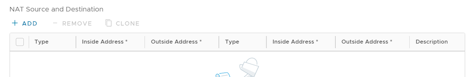
Configure ICMP Probes/Responders
ICMP handlers may be needed to enable integration with an external router that is performing dynamic routing functionality and needs stateful information about route reachability through VeloCloud. You can configure the ICMP Probes and Responders by navigating to the page.
Configure ICMP Probes
- In the SD-WAN Service of Enterprise Portal, select . The Edges page displays the existing Edges.
- Select the link to an Edge you want to configure ICMP Probes or select the View link in the Device column of the Edge. The configuration options for the selected Edge are displayed in the Device tab.
- Scroll down to the Routing & NAT category, select and expand the ICMP Probes section.
Figure 69. ICMP Probes 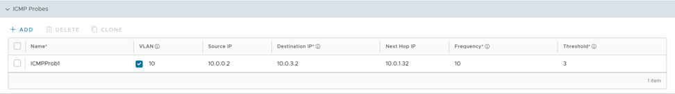
- To create ICMP Probes, select +Add and enter the following details:
Table 37. ICMP Probes Option Descriptions Field Description Name An unique name for the ICMP Probe. VLAN Select the check box to activate VLAN and enter the VLAN ID. Source IP The IP address of the Source. Destination IP The Destination IP address to ping. Next Hop IP The Next Hop IP address. Frequency The frequency in seconds to send ping requests. The allowable range is 1 through 60. Threshold The number of missed ping replies that will cause the routes to be marked unreachable. The allowable range is 1 through 10. Note: ICMP probe replies should be received within 100 milliseconds. If three replies do not arrive before 100 milliseconds, the probe status will be marked as down. - Select Save Changes.
- To clone an ICMP Probe, select an item and select Clone.
- To delete an ICMP Probe, select Delete.
Configure ICMP Responders
- In the SD-WAN service of Enterprise portal, select . The Edges page displays the existing Edges.
- Select the link to an Edge you want to configure ICMP Responders or select the View link in the Device column of the Edge. The configuration options for the selected Edge are displayed in the Device tab.
- Scroll down to the Routing & NAT category, select and expand the ICMP Responders section.
Figure 70. ICMP Responders 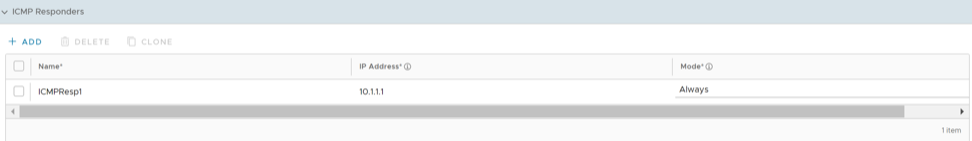
- To create ICMP Responders, select +Add and enter the following details:
Table 38. ICMP Responders Field Descriptions Field Description Name An unique name for the ICMP Responder. IP Address An IP address (virtual IP) that will respond to Ping requests. Mode Determines whether to respond to pings Always or Conditional. Select any one of the following: - Always: Edge always responds to ICMP pings.
- Conditional: Edge responds to ICMP pings only when the VPN tunnels are connected.
- Select Save Changes.
- To clone an ICMP Responder, select an item and select Clone.
- To delete an ICMP Responder, select Delete.
Configure Static Route Settings
Static Route Settings are useful for special cases in which static routes are needed for existing network attached devices, such as printers. You can add or delete Static Route Settings for an Edge. You can configure multiple static routes with different metrics, for the same network, on an Edge. However, only one static route is advertised to overlay for the network.
- In the SD-WAN service of Enterprise portal, select . The Edges page displays the existing Edges.
- Select the link to an Edge or select the View link in the Device column of the Edge. The configuration options for the selected Edge are displayed in the Device tab.
- Scroll down to the Routing & NAT category, select the Static Route Settings section.
- In the IPv4 tab, you can configure the static routes for IPv4 addresses.
Figure 71. IPv4 Tab 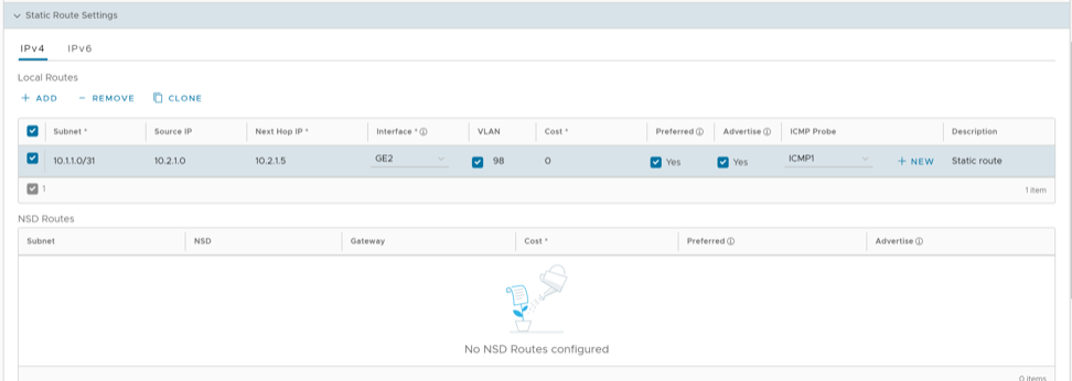
You can select the IPv6 tab to configure static routes for IPv6 addresses.
Figure 72. IPv6 Tab 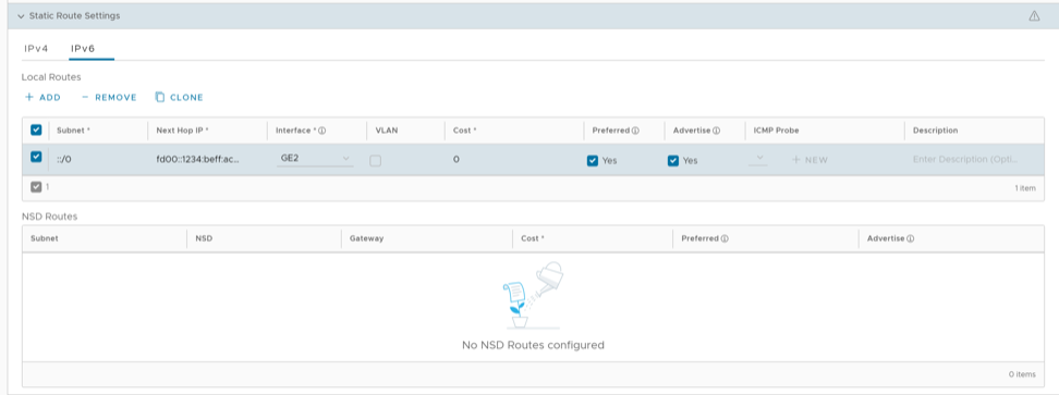
Configure the settings as follows:
Table 39. IPv4/IPv6 Option Descriptions Option Description Subnet Enter the IPv4 or IPv6 address of the Static Route Subnet that should be advertised. The IPv6 Subnet supports the following address format:- IPv6 global unicast address (2001:CAFE:0:2::1)
- IPv6 unique local address (FD00::1234:BEFF:ACE:E0A4)
- IPv6 Default (::/0)
Source IP Enter the corresponding IPv4 or IPv6 address of the selected VLAN. This option is available only when you select the VLAN check box. Next Hop IP Enter the next hop IPv4 or IPv6 address for the static route. The IPv6 next hop supports the following address format:
- IPv6 global unicast address (2001:CAFE:0:2::1)
- IPv6 unique local address (FD00::1234:BEFF:ACE:E0A4)
- IPv6 link-local address (FE80::1234:BEFF:ACE:E0A4)
Interface Choose the WAN Interface to which the static route would be bounded. Note: This option is displayed as N/A, if the next hop IP address is a part of the Edge's VLAN configuration. In this case, the interface is defined by the VLAN configuration.VLAN Select the check box and enter the VLAN ID. Cost Enter the cost to apply weightage on the routes. The range is from 0 to 255. Preferred Select the check box to match the static route first, even if a VPN route with lower cost is available. If you do not select this option, then any available VPN route is matched, even when the VPN route has higher cost than the static route. The static route will be matched only when the corresponding VPN routes are not available.
Note: This option is not available for IPv6 address type.Advertise Select the check box to advertise the route over VPN. Other Edges in the network will have access to the resource. Do not select this option when a private resource like a tele-worker's personal printer is configured as a static route and other users should be prevented from accessing the resource. Note: This option is not available for IPv6 address type.ICMP Probe Choose an ICMP probe from the drop-down menu or select the +New button to create a new ICMP probe. The Edge uses ICMP probe to check for the reachability of a particular IP address and notifies to failover if the IP address is not reachable. Note: This option is not supported for IPv6 address type.Description Enter an optional description for the static route. In addition, you can configure the NSD Static Routes. The NSD Static Routes that are configured in the Network Services gets listed in the Static Route Settings section for IPv4 addresses. You can edit the additional flags like the Cost, Preferred, and Advertise options. The Gateway column is updated only for NSD Static Routes via Gateway. You cannot edit the Advertise option for NSD Static Routes from Gateway.
- Select Save Changes in the Device tab.
Configure DNS for Edges
Domain Name System (DNS) is used to configure conditional DNS forwarding through a private DNS service and to specify a public DNS service to be used for querying purpose.
The DNS Service can be used for a public DNS service or a private DNS service provided by your company. A Primary Server and Backup Server can be specified. The public DNS service is preconfigured to use Google and Open DNS servers.
The DNS settings are applied to all the Edges associated with the Profile. You can choose to override the DNS settings for an Edge.
- In the SD-WAN Service of the Enterprise portal, go to . The Edges page displays the existing Edges.
- Select the link to an Edge or select the View link in the Device column of the Edge. The configuration options for the selected Edge are displayed in the Device tab.
- In the Routing & NAT category, select DNS. The DNS settings configured for the associated Profile are displayed. If required, you can select the Override check box and modify the DNS settings.
Figure 73. DNS Override 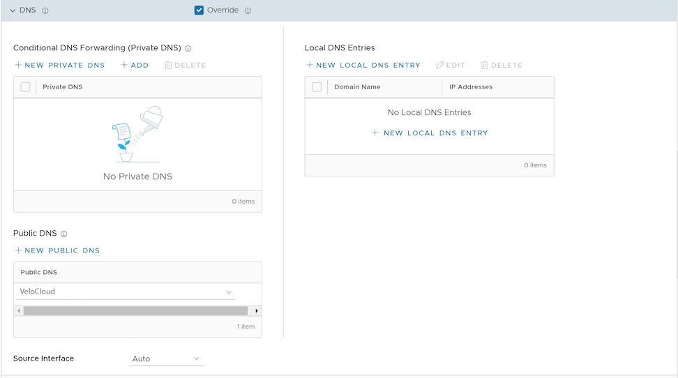
- From the Source Interface menu, select an Edge interface configured for the segment. This interface will be the source IP for the DNS service.
Note: When the Edge transmits the traffic, the packet header has the IP address of the selected source interface, whereas the packets can be sent through any interface based on the destination route.
- After updating the required settings, select Save Changes in the Device page.
Activate OSPF for Edges
Open Shortest Path First (OSPF) can be enabled on a LAN (routed and switched) or a WAN interface. But only a LAN interface can be activated as an active or passive interface. The Edge will only advertise the prefix associated with that LAN switch port. To get full OSPF functionality, you must use it in routed interfaces. After you configure the OSPF settings at the Profile level, all the Edges associated with the Profile will inherit the OSPF configuration from the Profile. However, you cannot override the OSPF configuration settings at the Edge level.
- In the SD-WAN service of the Enterprise portal, select .
- Select the Device icon next to an Edge, or select the link to an Edge and then select the Device tab.
- Go to the Routing & NAT section and select the arrow next to OSPF.
- In the OSPF section, you can view all the inherited OSPF configuration such as OSPF areas, Redistribution settings for OSPFv2/v3, BGP settings, and Route Summarization.
Configure BGP from Edge to Underlay Neighbors for Edges
You can override the inherited Profile settings at the Edge level when configuring BGP from the Edge to Underlay Neighbors.
- In the SD-WAN service of the Enterprise portal, select . The Edges page displays the existing Edges.
- Select the link to an Edge or select the View link in the Device column of the Edge.
- Go to the Routing & NAT section and select the arrow next to BGP to expand.
- The BGP settings configured for the associated Profile are displayed. If required, you can select the Override check box and modify the BGP Settings.
Note: When overriding and configuring BGP neighbors at the Edge level, any Profile-level filters associated with the neighbors will be removed when you switch the Edge from one profile to another. So at the Edge level, you must make sure to re-associate the filters with the BGP neighbors after switching the Edge profile.
- In addition to the BGP settings configured for a Profile, you can select an Edge Interface configured in the segment as the source Interface for BGP. For the IPv4 address type, you can select only the Loopback Interface as Source Interface and for the IPv6 address type, you can select any Edge Interface as the Source Interface.
This field is available:
- Only when you choose to override the BGP Settings at the Edge level.
- For eBGP, only when Max-hop count is more than 1. For iBGP, it is always available as iBGP is inherently multi-hop.
Important:- You cannot select an Edge Interface if you have already configured a local IP address in the Local IP field.
- You cannot configure a local IP address if you have selected an Edge Interface in the Source Interface drop-down list.
- Select Save Changes in the Device screen to save the modified configuration.
Configure High Availability Settings for Edges
- Scroll down to the High Availability section and expand HA.
Figure 75. High Availability 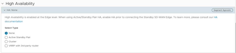
Configure VRRP Settings
You can configure Virtual Router Redundancy Protocol (VRRP) on an Edge to enable next-hop redundancy in the Orchestrator network by peering with third-party CE router. You can configure an Edge to be a primary VRRP device and pair the device with a third-party router.
- You can enable VRRP only between the Edge and third party router connected to the same subnet through an L2 switch.
- You can add only one Edge to the VRRP HA group in a branch.
- You cannot enable both Active-Standby HA and VRRP HA at the same time.
- VRRP is supported on primary routed port, sub-interface, and VLAN interfaces.
- Edge must be configured as the primary VRRP device, by setting higher priority, in order to steer the traffic through SD-WAN.
- If the Edge is configured as the DHCP server, then virtual IP addresses are set as the default Gateway address for the clients. When you use a separate DHCP server relay for the LAN, then the admin must configure the VRRP virtual IP address as the default Gateway address.
- When DHCP server is enabled in both the Edge and third-party router, then split the DHCP pool between the Edge and third party router, to avoid the overlapping of IP addresses.
- VRRP is not supported on an interface enabled with WAN Overlay, that is on the WAN link. If you want to use the same link for LAN, then create a sub-interface and configure VRRP on the sub-interface.
- You can configure only one VRRP group in a broadcast domain in a VLAN. You cannot add additional VRRP group for the secondary IP addresses.
- Do not add WI-FI link to the VRRP enabled VLAN. As the link failure would never happen, the Edge always remains as the primary device.
The following illustration shows a network configured with VRRP:
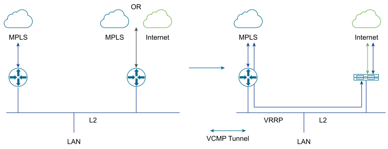
- In the VRRP Settings, select +Add and configure the following:
Figure 77. VRRP Settings for an Edge 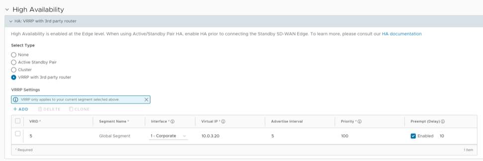
Table 40. VRRP Settings- Options and Descriptions Option Description VRID Enter the VRRP group ID. The range is from 1 to 255. Segment Name Displays the current Segment selected for Edge configuration. Note: The VRRP settings apply only to the current Segment that is selected.Interface Select a physical or VLAN Interface from the list. The VRRP is configured on the selected Interface. Virtual IP Enter a virtual IP address to identify the VRRP pair. Ensure that the virtual IP address is not the same as the IP address of the Edge Interface or the third-party router. Advertise Interval Enter the time interval with which the primary VRRP device sends VRRP advertisement packets to other members in the VRRP group. Priority To configure the Edge as primary VRRP device, enter a value that exceeds the priority value of the third-party router. The default is 100. Preempt Delay Select the check box and enter the preempt delay value so that Edge can preempt the third-party router which is currently the primary device, after the specified preempt delay.
Monitor VRRP Events
You can monitor the events related to changes in VRRP status.
In the SD-WAN service of Enterprise portal, click .
- VRRP HA updated to primary
- VRRP HA updated out of primary
- VRRP Failed
Configure Visibility Mode for Edges
This section discusses how to configure Visibility mode at the Edge level.
By default, the Visibility mode is inherited by the Edges associated with the Profile. To configure the visibility mode for an Edge:
- Scroll down to the Telemetry category and go to the Visibility Mode area and select the Override check box.
Figure 78. Visibility Mode for an Edge 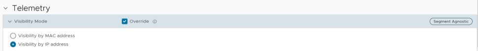
Configure Syslog Settings for Edges
In an Enterprise network, Orchestrator supports collection of Orchestrator bound events and firewall logs originating from enterprise Edge to one or more centralized remote syslog collectors (Servers), in native syslog format. At the Edge level, you can override the syslog settings specified in the Profile by selecting the Enable Edge Override check box.
To override the Syslog settings at the Edge level, perform the following steps.
- Scroll down to the Telemetry category and go to the Syslog area and select the Override check box.
Figure 79. Syslog Settings for an Edge 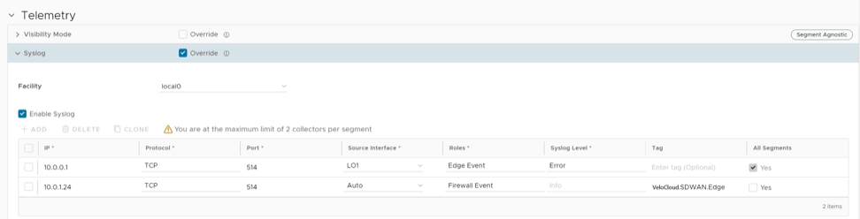
For additional information about Firewall settings at the Edge level, see Configure Edge Firewall.
Configure Netflow Settings for Edges
As an Enterprise Administrator, at the Edge level, you can override the Netflow settings specified in the Profile by selecting the Override check box.
To override the Netflow settings at the Edge level, perform the following steps:
- Scroll down to the Telemetry category and go to the Netflow Settings area and select the Override check box.
Figure 80. Netflow Settings for an Edge 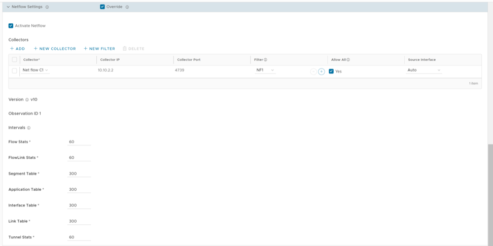
After you enable Netflow on the VeloCloud Edge, it periodically sends messages to the configured collector. The contents of these messages are defined using IPFIX templates. For additional information on templates, see IPFIX Templates.
Configure SNMP Settings for Edges
- In the SD-WAN service of the Enterprise portal, go to .
- Select the link to the required Edge, and then go to the MIBs for Edge area. Select VELOCLOUD-EDGE-MIB from the drop-down menu, and then select Run.
- Copy and paste the results onto your local machine.
- Install all MIBs required by VELOCLOUD-EDGE-MIB on the SNMP manager, including SNMPv2-SMI, SNMPv2-CONF, SNMPv2-TC, INET-ADDRESS-MIB, IF-MIB, UUID-TC-MIB, and VELOCLOUD-MIB. All these MIBs are available on the Remote Diagnostics page.
- SNMP MIB-2 System
- SNMP MIB-2 Interfaces
- VELOCLOUD-EDGE-MIB
Simple Network Management Protocol (SNMP) is a commonly used protocol for network monitoring, and Management Information Base (MIB) is a database associated with SNMP to manage entities. In the Orchestrator , you can activate SNMP by selecting the desired SNMP version. At the Edge Level, you can override the SNMP settings specified in the Profile.
At the Edge level, you can override the SNMP settings specified in the Profile, by selecting the Override check box. The Edge Override option enables Edge specific edits to the displayed settings, and discontinues further automatic updates from the configuration Profile for this module. For ongoing consistency and ease of updates, it is recommended to set configurations at the Profile level rather than Edge level.
Procedure to Configure SNMP Settings at Edge Level:
- You can select either Enable Version 2c or Enable Version 3, or both SNMP version check boxes.
Figure 81. SNMP Settings for an Edge 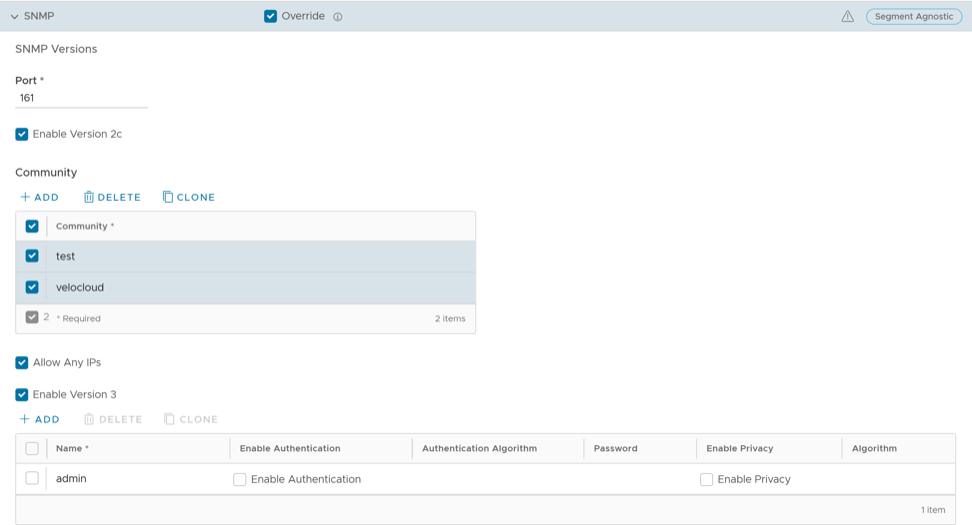
- Navigate to , and then select a Profile.
- Select the View link in the Firewall column.
- Go to Edge Access located under the Edge Security area.
- Configure SNMP Access and select Save Changes .
Security Virtual Network Functions
Virtual Network Functions (VNFs) are individual network services, such as routers and firewalls, running as software-only virtual machine (VM) instances on generic hardware. For example, a routing VNF implements all the functions of a router but runs in a software-only form, alone or along with other VNFs, on generic hardware. VNFs are administered and orchestrated within the NFV architecture.
- Insert network services in an optimal location to provide appropriate security. For example, insert a VNF firewall in an Internet-connected branch office rather than incur the inefficiency of an MPLS link to hairpin traffic through a distant data center to be firewalled.
- Optimize application performance. Traffic can follow the most direct route between the user and the cloud application using a VNF for security or traffic prioritization. In a VM environment, several VNFs may run simultaneously, isolated from each other, and can be independently changed or upgraded.
The following tables list the third-party firewalls supported by Arista along with the support matrix:
| VeloCloud Edge Platform | Edge 520v | Edge 840 | Edge 620 | Edge 640 | Edge 680 |
|---|---|---|---|---|---|
| Recommended VM Series Firewall Models | VM-50 Lite | VM-100 | VM-50 Lite | VM-100 | VM-100 |
| Number of vCPUs available for VM-Series Firewall | 2 | 2 | 2 | 2 | 2 |
| Memory available for VNF | 4.5 GB | 6.5 GB | 4.5 GB | 6.5 GB | 6.5 GB |
| Storage space available on Edge for VNF | 64 GB | 120 GB | 64 GB | 120 GB | 120 GB |
| Arista software version | Release 3.2.0 or later | Release 3.2.0 or later | Release 3.4.3 or later | Release 3.4.3 or later | Release 3.4.3 or later |
| Panorama version | Release 8.0.5 or later | Release 8.0.5 or later | Release 8.0.5 or later | Release 8.0.5 or later | Release 8.0.5 or later |
| VeloCloud Edge Platform | Edge 520v | Edge 840 | Edge 620 | Edge 640 | Edge 680 |
|---|---|---|---|---|---|
| Memory available for VNF | 2 GB | 4 GB | 2 GB | 4 GB | 4 GB |
| Number of vCPUs available for VNF | 2 | 2 | 2 | 2 | 2 |
| Storage available on Edge for VNF | 64 GB | 100 GB | 120 GB | 120 GB | 120 GB |
| Maximum Throughput of SD-WAN and Checkpoint VNF | 100 Mbps | 1 Mbps | 300 Mbps | 600 Mbps | 1 Gbps |
| Arista software version | Release 3.3.2 or later | Release 3.3.2 or later | Release 3.4.3 or later | Release 3.4.3 or later | Release 3.4.3 or later |
| Checkpoint VNF OS version | Release R77.20 or later | Release R77.20 or later | Release R77.20 or later | Release R77.20 or later | Release R77.20 or later |
| Checkpoint manager software version | Release 80.30 or later | Release 80.30 or later | Release 80.30 or later | Release 80.30 or later | Release 80.30 or later |
| VeloCloud Edge Platform | Edge 520v | Edge 840 | Edge 620 | Edge 640 | Edge 680 |
|---|---|---|---|---|---|
| Recommended VM Series Firewall Models | VM00, VM01, VM01v | VM00, VM01, VM01v, VM02, VM02v | VM00, VM01, VM01v | VM00, VM01, VM01v, VM02, VM02v | VM00, VM01, VM01v, VM02, VM02v |
| Memory available for VNF | 2 GB | 4 GB | 2 GB | 4 GB | 4 GB |
| Number of vCPUs available for VNF | 2 | 2 | 2 | 2 | 2 |
| Storage available on Edge for VNF | 64 GB | 100 GB | 64 GB | 100 GB | 100 GB |
| Maximum Throughput of SD-WAN and FortiGate VNF | 100 Mbps | 1 Mbps | 300 Mbps | 600 Mbps | 1 Gbps |
| Arista software version | Release 3.3.1 or later | Release 3.3.1 or later | Release 4.0.0 or later | Release 4.0.0 or later | Release 4.0.0 or later |
| FortiOS version | Release 6.0 and 6.2.0
Starting from release 4.0.0, FortiOS version 6.4.0 and 6.2.4 are supported. |
Release 6.0 and 6.2.0
Starting from release 4.0.0, FortiOS version 6.4.0 and 6.2.4 are supported. |
Release 6.4.0 and 6.2.4 | Release 6.4.0 and 6.2.4 | Release 6.4.0 and 6.2.4 |
You can deploy and forward traffic through VNF on an Edge.
Configure VNF Management Service
Arista supports third-party firewalls that can be used as VNF to pass traffic through Edges.
Choose the third-party firewall and configure the settings accordingly. You may need to configure additional settings in the third-party firewall as well. Refer to the deployment guides of the corresponding third-party firewall for the additional configurations.
For the VNF Types Check Point Firewall and Fortinet Firewall configure the VNF image by using the System Property edge.vnf.extraImageInfos. You must be an Operator user to configure the system property. If you do not have the Operator role access, contact your Operator to configure the VNF Image.
- In the SD-WAN service of the Enterprise portal, go to , and then under Edge Services area, expand VNFs.
Figure 82. Edge Services 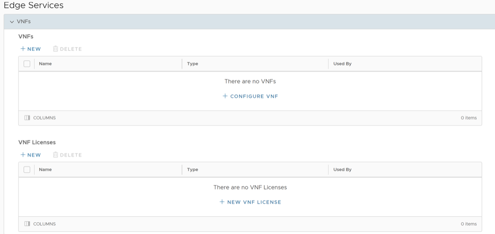
- In the Configure VNF window, enter a descriptive name for the security VNF service and select a VNF Type from the drop-down menu.
Figure 83. Configure VNF 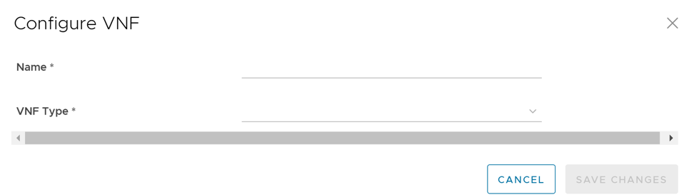
Configure Security VNF without High Availability
- Orchestrator and activated Edge running software versions that support deploying a specific security VNF. For additional information on the supported software versions and Edge platforms, refer to the Support Matrix in Security Virtual Network Functions.
- Configured VNF Management service. For additional information, see Configure VNF Management Service.
You can deploy and forward traffic through VNF on the Edge, using third-party firewalls.
- In the Device tab, scroll down to the Security VNF section and select + Configure Security VNF.
The Configure Security VNF window appears.
Figure 84. Configure Security VNF 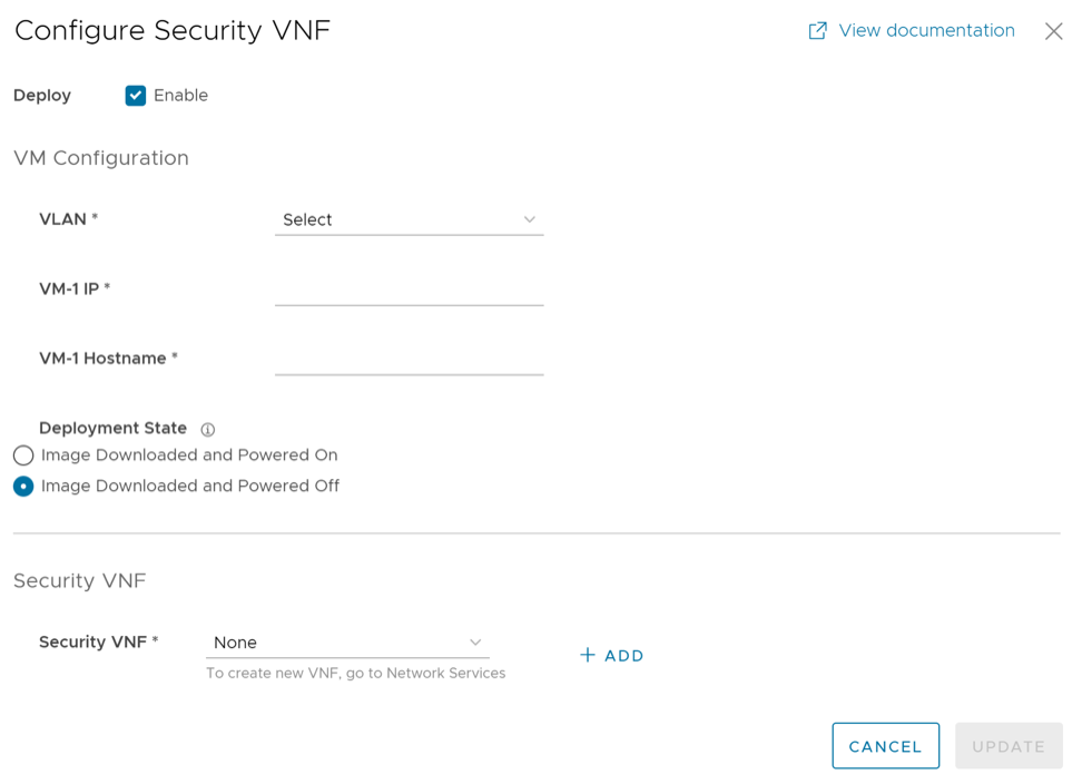
- Under Security VNF, choose a pre-defined VNF management service from the drop-down menu. You can also select + Add to create a new VNF management service. For additional information, see Configure VNF Management Service.
- The following image shows an example of Fortinet Firewall as the Security VNF type. If you choose Fortinet Firewall, configure the following additional settings:
Figure 85. Security VNF- Fortinet Firewall 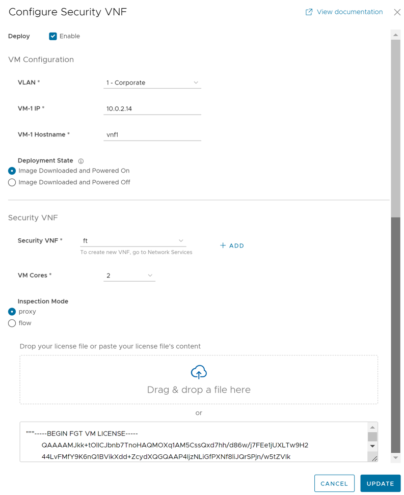
- VM Cores – Select the number of cores from the drop-down list. The VM License is based on the VM cores. Ensure that your VM License is compatible with the number of cores selected.
- Inspection Mode – Choose one of the following modes:
- Proxy – This option is selected by default. Proxy-based inspection involves buffering traffic and examining the data as a whole for analysis.
- Flow – Flow-based inspection examines the traffic data as it passes through the FortiGate unit without any buffering.
- License – Drag and drop the VM License or paste your license content in the text box.
- The following image shows an example of Check Point Firewall as the Security VNF type.
Figure 86. Security VNF- Check Point Firewall 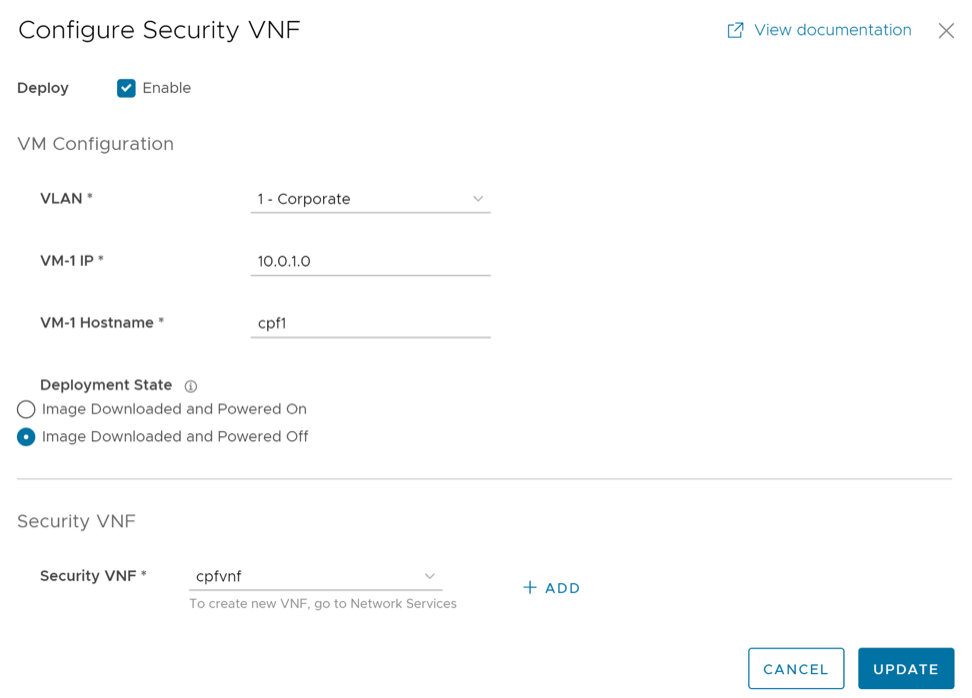
- If you choose Palo Alto Networks Firewall as Security VNF, configure the following additional settings:
Figure 87. Security VNF- Palo Alto Networks Firewall 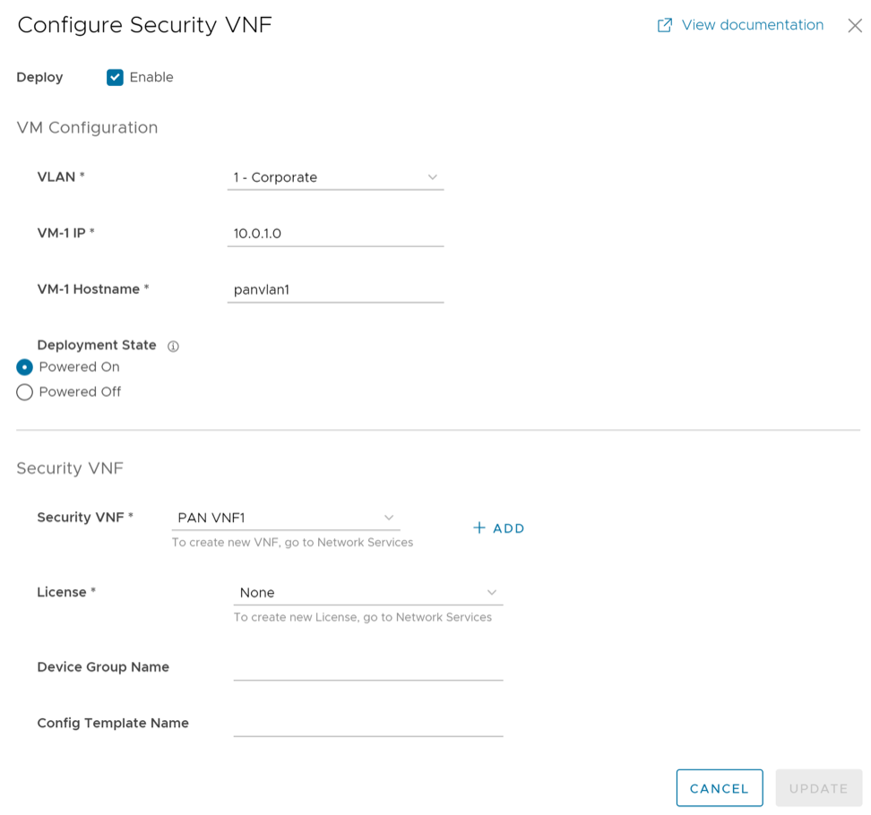
- License – Select the VNF License from the drop-down list.
- Device Group Name – Enter the device group name pre-configured on the Panorama Server.
- Config Template Name – Enter the configuration template name pre-configured on the Panorama Server.
Note: If you want to remove the deployment of Palo Alto Networks Firewall configuration from a VNF type, ensure that you have deactivated the VNF License of Palo Alto Networks before removing the configuration.
- The following image shows an example of Fortinet Firewall as the Security VNF type. If you choose Fortinet Firewall, configure the following additional settings:
- Select Update.
The configuration details are displayed in the Security VNF section.
Figure 88. Security VNF 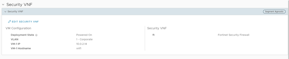
If you want to redirect multiple traffic segments to the VNF, define mapping between Segments and service VLANs. See Define Mapping Segments with Service VLANs.
You can insert the security VNF into both the VLAN as well as routed interface to redirect the traffic from the VLAN or the routed interface to the VNF. See Configure VLAN with VNF Insertion.
Configure Security VNF with High Availability
- Orchestrator and activated Edge running software version 4.0.0 or later. For additional information on the supported Edge platforms, refer to the Support Matrix in Security Virtual Network Functions.
- Configured Check Point Firewall VNF Management service. For additional information, see Configure VNF Management Service.
Note: Arista supports only Check Point Firewall VNF on Edges with HA.
You can configure security VNF on Edges configured with High Availability to provide redundancy.
- In a standalone Edge, enable HA and VNF.
- In Edges configured with HA mode, enable VNF.
- LAN interface to VNF
- WAN interface to VNF
- Management Interface – VNF communicates with its manager
- VNF Sync Interface – Synchronizes information between VNFs deployed on Active and Standby Edges
The Edges have the HA roles as Active and Standby. The VNFs on each Edge run with Active-Active mode. The Active and Standby Edges learn the state of the VNF through SNMP. The SNMP poll is done periodically for every 1 second by the VNF daemon on the edges.
VNF is used in the Active-Active mode with user traffic forwarded to a VNF only from the associated Edge in Active mode. On the standby VM, where the Edge in the VM is standby, the VNF will have only traffic to the VNF Manager and data sync with the other VNF instance.
The following example shows configuring HA and VNF on a standalone Edge.
- Scroll down to the High Availability section and from the Select Type options, choose the Active Standby Pair.
Figure 89. High Availability 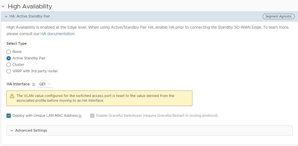
- Navigate to the Security VNF section and select + Configure Security VNF.
The Configure Security VNF window appears.
Figure 90. Configure Security VNF - Under Security VNF, choose a pre-defined Check Point Firewall VNF Management service from the drop-down list. You can also select New VNF Service to create a new VNF management service. For additional information, see Configure VNF Management Service.
Figure 91. Select Check Point Firewall
Define Mapping Segments with Service VLANs
When you want to redirect multiple traffic segments to the security VNF, define mapping between Segments and service VLANs.
To map the segments with the service VLANs:
- Define mapping between the segments and service VLANs by entering an unique Service VLAN ID for each segment.
Figure 92. Define Mapping Segments 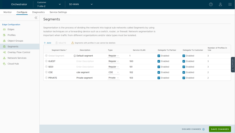
Configure VLAN with VNF Insertion
Ensure that you have created a security VNF and configured the settings. See Configure Security VNF without High Availability and Configure Security VNF with High Availability.
Map the segments with service VLANs to enable VNF insertion into the VLANs. See Define Mapping Segments with Service VLANs.
You can insert the security VNF into both the VLAN as well as routed interface.
- On the Device tab, under Connectivity, expand the VLAN section.
Figure 93. VLAN - In the Edit VLAN window, select the VNF Insertion check box to insert the VNF into VLAN. This option redirects traffic from a specific VLAN to the VNF.
Figure 94. Edit VLAN 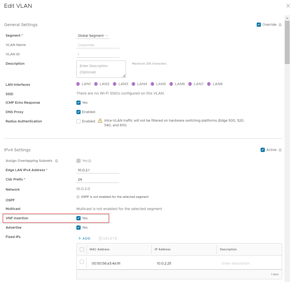
- Select Done.
The VLAN section displays the status of the VNF insertion.
Figure 95. VNF Insertion Status 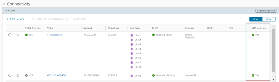
You can also insert the VNF into Layer 3 interfaces or sub-interfaces. This insertion redirects traffic from the Layer 3 interfaces or subinterfaces to the VNF.
If you choose to use the routed interface, ensure that the trusted source is checked and WAN overlay is turned off on that interface. For additional information, see Configure Interface Settings for Edges.
Monitor VNF for an Edge
You can monitor the status of VNFs and the VMs for an Edge, and also view the VNF network services configured for the Enterprise.
To monitor the status of VNFs and VMs of an Edge:
- In the SD-WAN service of the Enterprise portal, select .
The list of Edges along with the details of configured VNFs appears as shown below.
Figure 96. Monitor VNF for an Edge 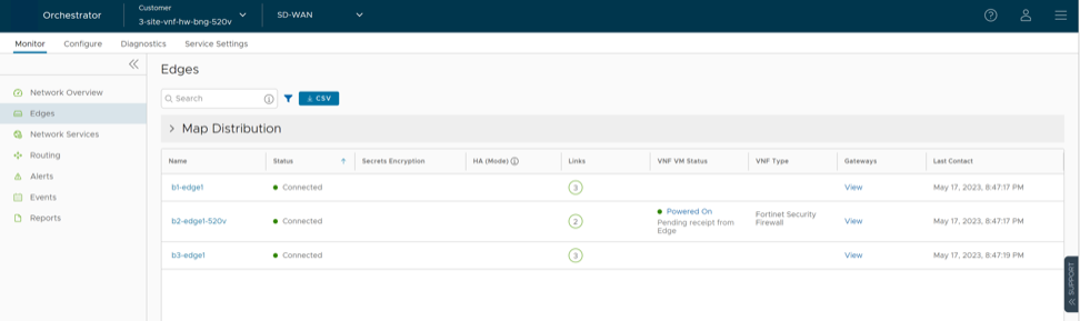
- For the VNFs configured on Edge with HA, the VNF Virtual Machine Status window consists of an additional column that displays the serial number of the Edges, as shown below.
Figure 97. Serial Number 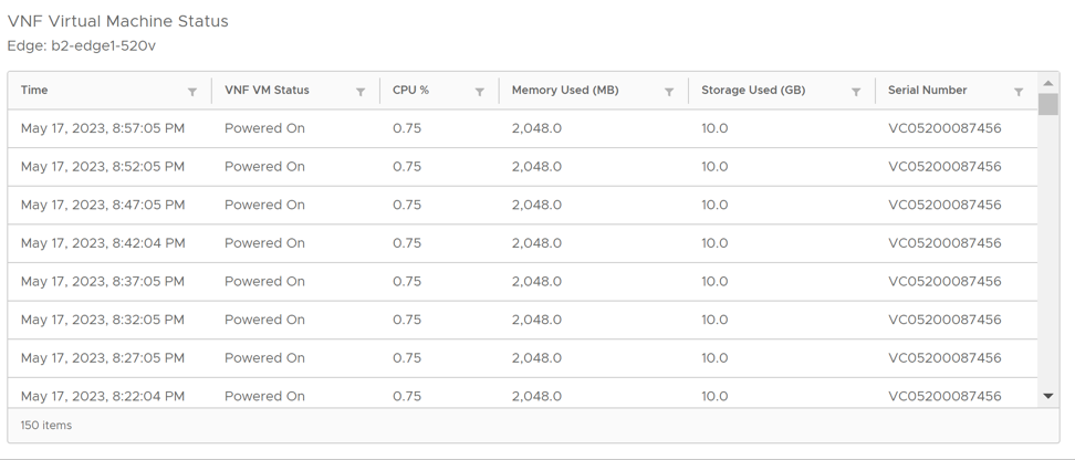
- To monitor the status of VNFs and VMs:
- In the SD-WAN service of the Enterprise portal, select .
The list of Edges along with the details of configured VNFs is displayed.
Figure 98. Edge VNFs 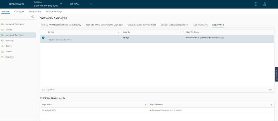
- In the SD-WAN service of the Enterprise portal, select .
Monitor VNF Events
You can view the events when the VNF VM is deployed, when there is a change in the VNF VM configuration, and when a VNF insertion is enabled in a VLAN.
In the SD-WAN service of the Enterprise portal, select .
To view the events related to VNF, you can use the filter option. Select the drop-down arrow next to the Search option and choose to filter either by the Event or by the Message column.
- VNF deployed
- VNF deleted
- VNF turned off
- VNF error
- VNF is DOWN
- VNF is UP
- VNF power off
- VNF power on
- VNF insertion turned off
- VNF insertion turned on
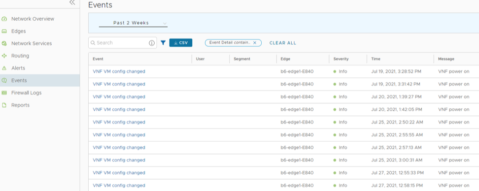
Configure VNF Alerts
You can configure to receive alerts and notifications related to the VNF events.
To configure alerts and notifications related to the VNF events:
- In the SD-WAN service of the Enterprise portal, select .
The Alert Configuration screen appears.
Figure 100. Alert Configuration 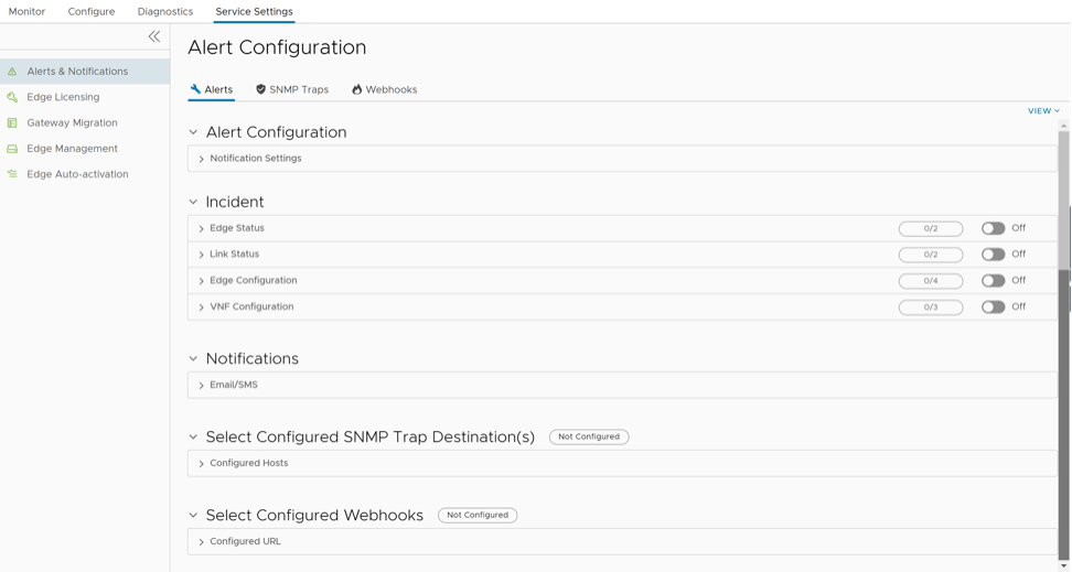
- Under Incidents, select and expand VNF Configuration and turn on the toggle button.
Figure 101. VNF Configuration 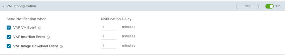
Configure Authentication Settings for Edges
The Device Authentication Settings allows you to select a Radius server to authenticate a user.
At the Edge-level, you can choose to override the Authentication Settings configured for the Profile.
- Select to expand the Authentication area and select the Override check box.
Figure 102. Authentication Settings for an Edge 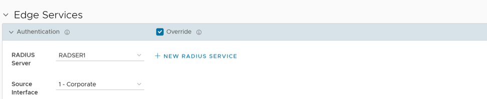
Configure NTP Settings for Edges
NTP has the following prerequisites:
- To configure an Edge to act as an NTP Server for its Clients, you must first configure the Edge's own NTP time sources by defining Private NTP Servers under .
As an Enterprise Administrator, at the Edge level, you can override the Network Time Protocol (NTP) settings specified in the Profile by selecting the Override checkbox. By default, at the Edge level, the NTP Servers are deactivated.
- NTP Clients can synchronize to LAN/loopback IP address of the Edge as NTP server but cannot synchronize to WAN IP address.
- NTP synchronization from another segment to LAN interface is not supported.
To override NTP settings at the Edge-level, perform the following steps.
- Select to expand the NTP area and select the Override check box.
Figure 103. NTP Settings for an Edge 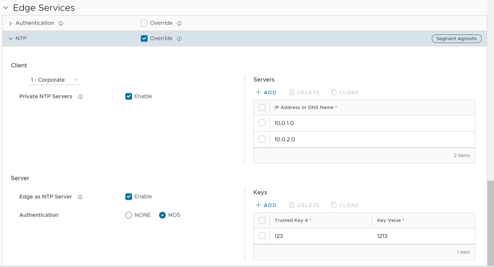
Debugging and troubleshooting are much easier when the timestamps in the log files of all the Edges are synchronized. You can collect NTP diagnostic logs by running the NTP Dump remote diagnostic tests on an Edge. For additional information about how to run remote diagnostic tests on an Edge, see Arista VeloCloud SD-WAN Troubleshooting Guide.
Configure TACACS Services for Edges
Describes how to configure TACACS Services for Edges.
Provision an Edge by following the steps in the topic Provision a New Edge.
- Under Edge Services expand TACACS Services.
Figure 104. TACACS Services for an Edge