Configure Edge for Amazon Web Services (AWS) Transit Gateway (TGW) Connect Service
VeloCloud Edges typically deploy in a Transit VPC on Amazon Web Services (AWS). AWS introduced support for AWS TGW (Transit Gateway) Connect Service for SD-WAN appliances to connect to the Transit Gateway. VeloCloud Edge now has a feature, BGP over GRE support on LAN, that supports the VeloCloud Edge and uses the AWS TGW Connect Service for connectivity to the AWS Transit Gateway.
For the AWS TGW Connect Service, the Edge provisioned in the Transit VPC use the LAN, routed and non-WAN interfaces to set up the GRE tunnel.
AWS Configuration Procedure
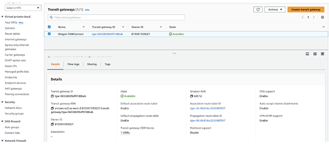
In the AWS portal, provision an AWS Transit Gateway for a particular region. This same region must have the Transit VPC with the VeloCloud Edge provisioned.
Figure 1. Transit Gateways
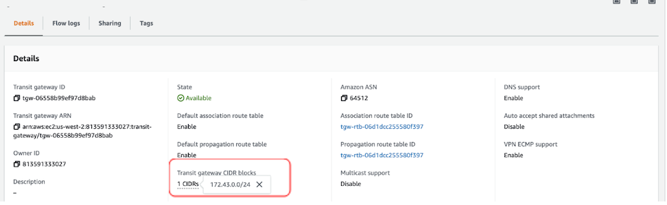
Check for the Transit Gateway CIDR block to configure. Use an IP from this block for the GRE endpoint on the AWS TGW. The Amazon ASN later uses it in the BGP configuration on the VeloCloud Edge.
Figure 2. Transit Gateway CIDR Block Information
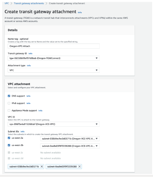
Create a VPC Attachment for the Transit VPC specifying the Subnets of the LAN interface where the Edge or EI resides.
Figure 3. Create Transit Gateway Attachment
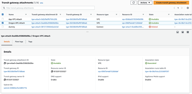
After creating the VPC Attachment, the state Available appears in the State column.
Figure 4. VPC Attachment Status
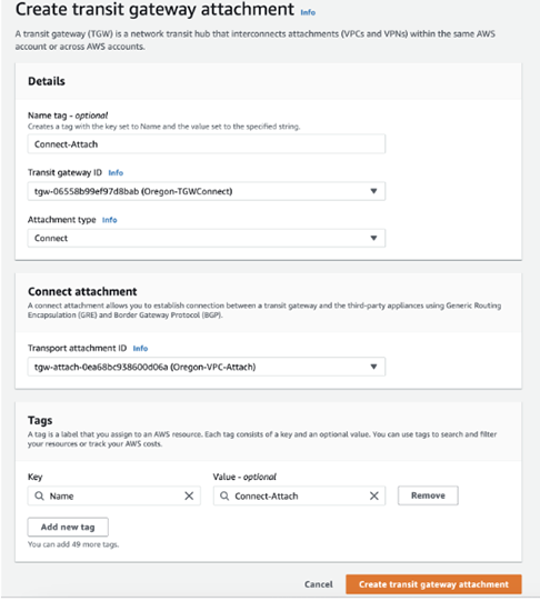
Create a Connect Attachment using the VPC Attachment.
Figure 5. Create Connect Attachment
After creating the Connect Attachment, the state, Available, displays in the State column.
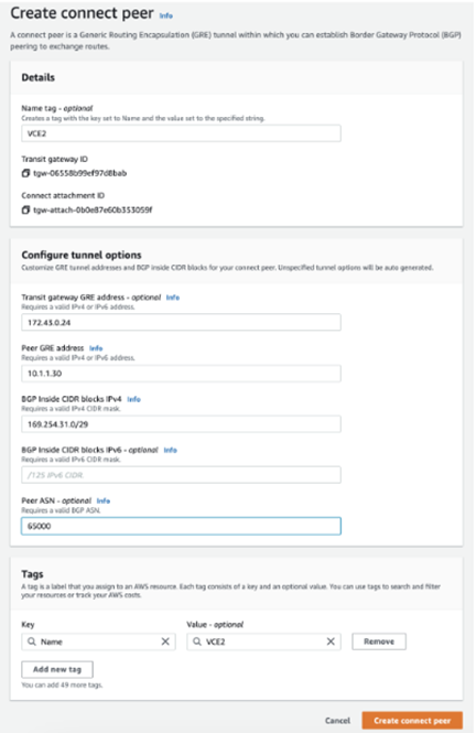
Create a Connect peer, which translates to a GRE Tunnel. Specify the following parameters:
Transit Gateway GRE Address
Peer GRE Address
BGP Inside CIDR block
Peer ASN
The BGP Inside CIDR block and the Peer ASN must match the configuration on the VeloCloud Edge.
Figure 6. Create Connect Peer
The example displays the following configuration:
172.43.0.24 - the GRE Outside IP address on the AWS TGW allocated from the Transit Gateway CIDR block.
10.1.1.30 - the GRE Outside IP address on the VeloCloud Edge.
169.254.31.0/29 - the Inside CIDR Block. The addresses from this block are used for the BGP neighbor.
169.254.31.1 - the IP address on the VeloCloud Edge.
169.254.31.2 and 169.254.31.3 - addresses used for the BGP on the AWS TGW.
64512 - the BGP ASN configured on the AWS TGW.
65000 - the BGP ASN configured on the VeloCloud Edge.
Figure 7. Connect Peers
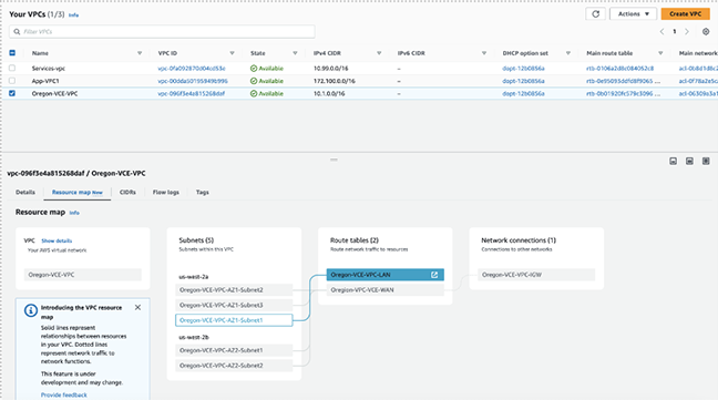
The VPC Resource Map for the Transit VPC lists the LAN-side subnet with the Route table.
Figure 8. VPC Resource Map
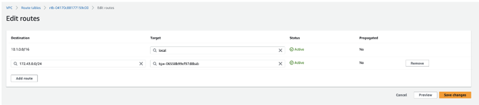
In the Transit VPC route table, add a route for the TGW CIDR block with Target or Next Hop as the VPC Attachment. For example, 172.43.0.0/24 denotes the AWS TGW CIDR block.
Figure 9. Edit Routes
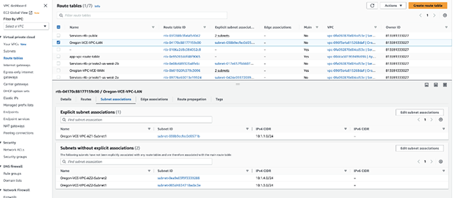
In the same route table, verify that the LAN EI subnet has an explicit Subnet association.
Figure 10. Subnet Association
VeloCloud Orchestrator Configuration Procedure
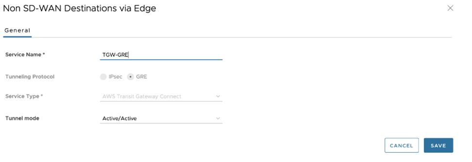
On the VeloCloud Orchestrator, navigate to Network Services > Non SD-WAN Destinations via Edge, and configure the GRE Tunnel with the AWS Transit Gateway Connect.
Figure 11. Non SD-WAN Destinations via Edge
When configuring the GRE Tunnel with the AWS Transit Gateway Connect service, see the following important notes:
The only configurable Tunnel Mode parameter is Active/Active.
There are no Keepalive mechanisms for the GRE tunnel with the AWS Transit Gateway Service.
BGP configured by default for the GRE tunnels, and uses BGP Keepalive(s) for the BGP neighbor status.
The Edge does not support ECMP across multiple tunnels. Therefore, only one GRE Tunnel can be used for egress Traffic.
The Tunnel Source interface must have a default gateway configured for the feature to work.
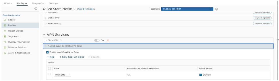
Under Profile, enable Cloud VPN, then enable Non SD-WAN Destination via Edge, and choose NSD.
Figure 12. Profile VPN Services
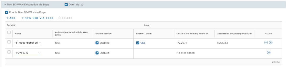
Under the Edge configuration in the Non SD-WAN Destinations via Edge, select the configured NSD.
Figure 13. Configured NSD
For the specific NSD, configure the GRE tunnel parameters by selecting the + sign. Configure the following:
Tunnel Source as the LAN interface
Tunnel Source IP as the IP address configured on the LAN interface, if specified dynamically use Remote Diagnostics > Interface Stats to obtain the IP address
TGW ASN
The Primary Tunnel parameters can be configured by providing the Destination IP, the IP address provided on the TGW Connect Peer
The Internal Network/Mask must be the same as specified in the TGW Connect Peer Inside configuration.
The Secondary Tunnel parameters can be configured for the Destination IP and Internal Network/Mask.
Figure 14. Add AWS TGW Connect Tunnel
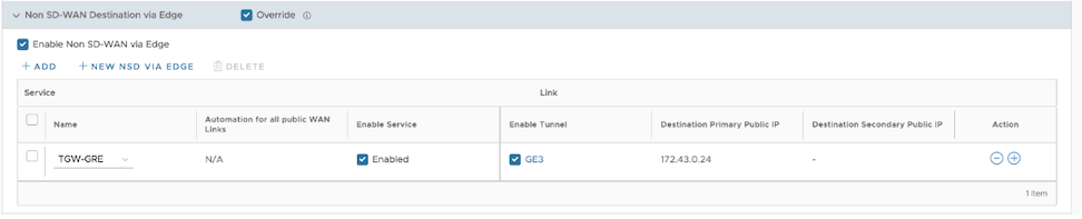
Orchestrator enables BGP by default for this feature. The Local ASN field pre-populates. The Non SD-WAN via Edge configuration displays.
Figure 15. Non SD-WAN via Edge Configuration
The configuration automatically creates the BGP configuration for the Neighbors. Orchestrator automatically creates each GRE Tunnel configuration towards the AWS Transit Gateway for two BGP Neighbors with information about the Link Name, Neighbor IP, Tunnel Type, and ASN.
Figure 16. NSD Neighbors
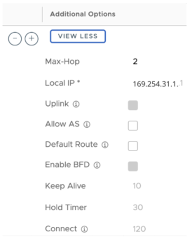
In Additional Options, configure the eBGP Max Hop as 2, a requirement for the TGW Connect Service. The additional parameters populated include Keepalive and Hold Timer based on the recommendation provided by AWS. The BGP Local IP also pre-populates. These parameters cannot be modified.
Figure 17. Additional Options
Orchestrator automatically adds two NSD BGP Neighbors.
Modifies the Additional Options field for Max-Hop, Local IP, Keep Alive, and Hold Timer values.
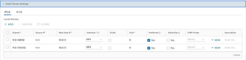
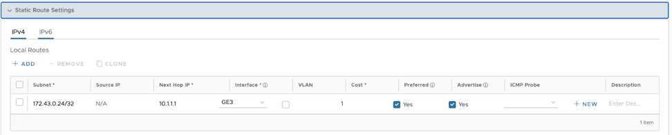
For the GRE tunnel endpoint, configure a static route on the VeloCloud Edge which specifies the Next-Hop to specify the Subnet Default Gateway and Interface as the LAN interface.
Figure 18. Static Route Settings
Obtaining Amazon Web Services Configuration Details
From Amazon Web Services, create VPC and VPN Connections. Refer to the instructions in the AWS documentation.
Make note of the Gateways associated with the enterprise account in the Orchestrator to create a virtual private gateway in the Amazon Web Services.
Make a note of the Public IP, Inside IP and PSK details associated with the Virtual Private Gateway. Users need to enter this information in the Orchestrator when users create a Non SD-WAN Destination.
Configure a Non SD-WAN Destination
After users obtain Public IP, Inside IP, and PSK information from the AWS portal, users can configure a Non SD-WAN Destination.
To configure a Non SD-WAN Destination through a Gateway, refer to one of the following:
AWS has announced Tunnel-less Connect on a Cloud WAN. This document describes AWS components and configuring AWS and VeloCloud SD-WAN.
AWS Cloud WAN CNE Connect uses a Tunnel-less BGP capability to provide a simpler way to build a global SD-WAN network using an AWS backbone as a middle-mile transport network. With this capability, VeloCloud SD-WAN appliances can natively peer with an AWS Cloud WAN using Border Gateway Protocol (BGP) without requiring tunneling protocols such IPsec or GRE. This simplifies the integration of an SD-WAN into an AWS cloud and enables leveraging the high-bandwidth AWS backbone for branch-to-branch connectivity across different geographic regions. This feature also supports in-built network segmentation and enables the building of a secure SD-WAN at a global scale.
Typically, VeloCloud SD-WAN Virtual Edges (vEdges) deploy into an AWS Transport VPC. This Transport VPC may then peer with other VPCs, TGWs, or, in this case, a CNE (Cloud Network Edge) in the Cloud WAN backbone to establish connectivity to resources in AWS.
For Cloud WAN CNE Connect, the vEdges provisioned in the Transport VPC use the LAN-facing routed and non-WAN interfaces to establish native L3 unencapsulated BGP peering with the CNE.
AWS Components
AWS requires the following components:
Cloud WAN Core Network
Policy definition
Core Network Edge (CNE)
Transport VPC
VPC Attachment
Connect Attachment
This assumes that users have other resources in other AWS VPCs that use VPC peering to connect to CNEs in the Core Network. If not, users must define the Core Network and CNEs and create the attachments to existing workload VPCs.
AWS Configuration
Use the following Arista online documentation to create vEdges in an AWS VPC:
Virtual Edge Deployment Guide
VeloCloud SD-WAN AWS Cloud Formation Template- Green Field
VeloCloud SD-WAN AWS Cloud Formation Template- Brown Field
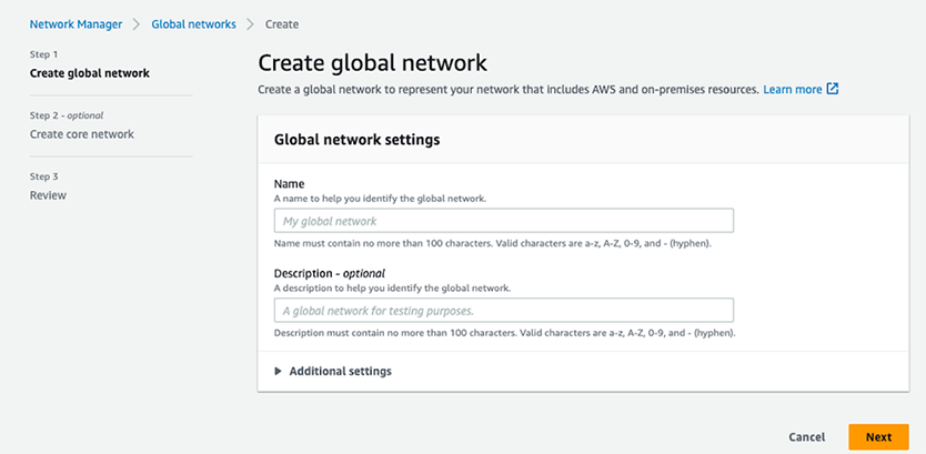
On the AWS console, use the AWS Network Manager to create a Global Network, if one does not already exist in the AWS deployment.
Figure 19. Create Global Network
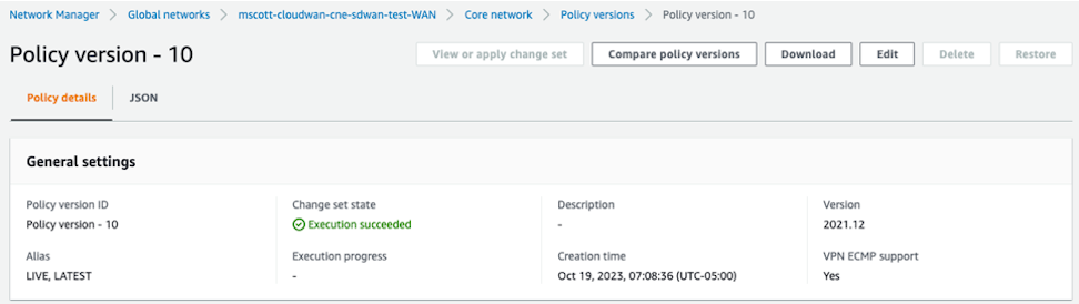
Create a Policy version.
A Policy version defines and configures the key details of the solution:
Figure 20. Policy Version
Enter the BGP ASN ranges used by the CNEs:
Figure 21. ASN Ranges
In the global Inside CIDR blocks field, define the respective CDR blocks for the CNEs.
Figure 22. Inside CIDR Blocks
Search for Edge locations and review the list of specific AWS AZ to place the CNE.
Figure 23. Edge Locations
Note: The ASN and Inside CIDR Blocks for each Edge location uses the defined range defined for the Global Network.
Search for Segments. Define logical segments using tags. Tag VPCs and Subnets to define segment membership. In this example, the format uses Key=Segment and Value=SDWAN.
Figure 24. Segments
Note: Use the value defined in the policy.
VCP and Connect Attachments specify the Segments used as well as the criteria for the Segments. In the example, a tag-value condition defines membership in the SD-WAN segment. The key-value pair uses the Condition values and must be present in VPCs and subnets in order to become Segment members.
Figure 25. Attachment Policies
Use one of the following types of attachments:
VPC Attachments
Connect Attachments
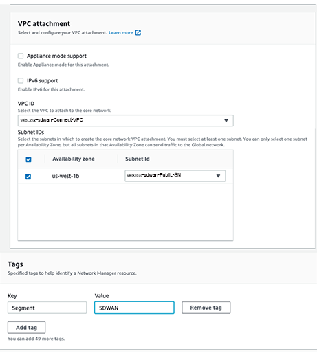
VPC Attachments - Each SD-WAN Transport VPC has a VPC attachment to the CNE. Specify at least one subnet within the VPC when creating the VPC attachment. In the example, the CNE with the location, us-west-1 AZ peers with the SD-WAN Transport VPC private VLAN subnet. Also, define a key-value pair for the Segment membership.
Figure 26. VPC Attachment
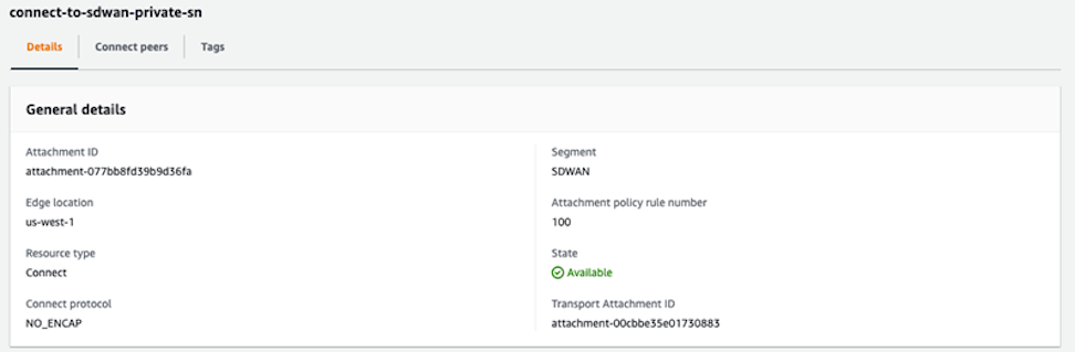
If configured correctly, the Attachment displays the configuration details including SDWAN as the Segment and the Attachment policy rule number.
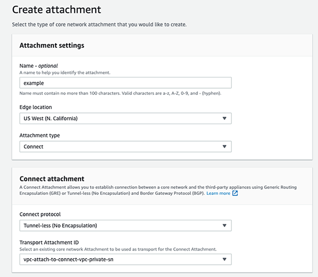
Configure the Connect Attachment for Tunnel-less (No encapsulation) and specify an existing VPC Attachment as the Transport Attachment ID.
Figure 27. Creating Attachment
Figure 28. Tags
If configured correctly, the Attachment displays membership in the SDWAN Segment. It also displays the Attachment policy rule number and NO-ENCAP as the Connect protocol.
Figure 29. Policy Details
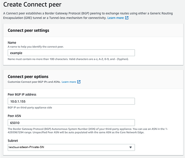
Create Connect Peers in the Connect Attachment and define the SD-WAN vEdge BGP peering in terms of the ASN and peer IP address.
Figure 30. Create Connect Peer
Once configured, the AWS console provides two Core Network BGP peer IP addresses to use on the SD-WAN BGP neighbors and selects them randomly from the Inside CIDR range configuration.
Configuring VeloCloud SD-WAN
Configure the BGP neighbors to connect with the two IP addresses provided by the AWS Cloud WAN in Connect Peers. The IP addresses originate from the Inside CIDR range defined in the policy, and requires creating static routes on the Edge to point to the CNE neighbor IPs using the LAN routed interface.
Note: Each Connect peer receives different BGP Core Network Peer IP address and in turn, Static Routes and BGP Neighbors receive different configurations.
When creating the BGP Neighbors, set the Max-Hop to two or more in the Additional Options column.
Figure 32. Additional Options
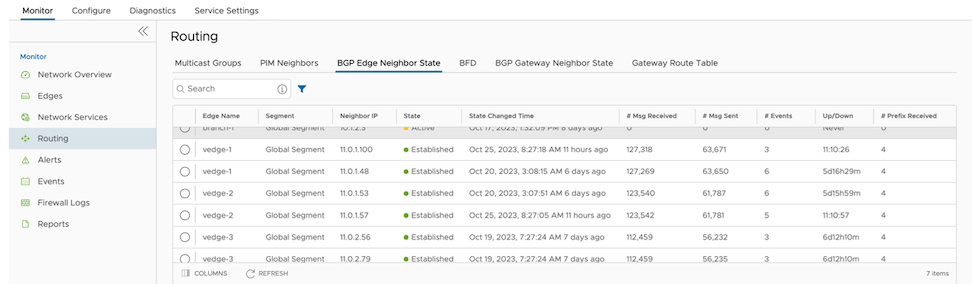
Use Monitor > Routing > BGP Edge Neighbor State to verify that the BGP peer relationship has established with the configured Neighbor IP addresses.
Figure 33. Routing
 The example displays the following configuration: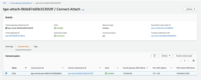




 Note: The ASN and Inside CIDR Blocks for each Edge location uses the defined range defined for the Global Network.
 Note: Use the value defined in the policy.