Connecting Serial and Management Cables
Connecting Supervisor Cables
Supervisor modules contain console, management, and USB ports. Figure 1 - Supervisor Ports (DCS-7300(-D)-SUP) displays status LED and port locations on the 7300 Series Modular switch supervisor.
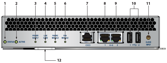
| 1 | Status LED | 5 | Fabric module status LED | 9 | Ethernet management port |
| 2 | Active LED | 6 | Fan module status LED | 10 | USB ports |
| 3 | Power supply status LED | 7 | Console serial port | 11 | Clock input port |
| 4 | Line card status LED | 8 | Ethernet management port | 12 | Release lever |
- Console (Serial) Port: Connect to a PC with RJ-45 to DB-9 serial adapter cable. Default switch settings include:
- 9600 baud
- No flow control
- 1 stop bit
- No parity bits
- 8 data bits
- Ethernet Management Port: Connect to 10/100/1000 management network with RJ-45 cable.
- USB Port: This may be used for software or configuration updates.
- Clock Input Port: The port type is MCX connector, 2-5.5V, 50 ohm termination.
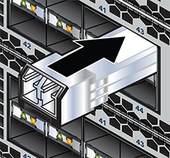
Connecting Linecard Modules and Cables
Install required SFP, SFP+, and QSFP+ optic modules in linecard module ports (Figure 2 - SFP or SFP+ Ports).
Connect cables as required to linecard module ports or RJ45 ports.
CAUTION: Excessive bending can damage interface cables, especially optical cables.