Rack Mounting the Switch
After completing the instructions for your rack type, proceed to Cabling the Switch.
Two-Post Rack Mount (19" rack)
The switches covered in this guide do not support two-post rack mounting. The accessory kit contains the parts required for the mounting kit ordered. Contact your local Arista Networks account representative for further information if you require other mounting types.
Four-Post Rack Mount (19" rack)
Perform the following tasks to mount the switch onto a four-post rack.
- Mounting bracket
- Rail
Each chassis side has attachment pins that align with bracket holes; the number of pins varies by switch model. Pin orientation is symmetric and central, with supporting bracket placement where the flange is either flush with the front and rear panels or not flush with the panels. Each bracket hole includes a key opening for placing the bracket flush with the chassis and then locking it into place.
Attachment pins must engage all bracket holes.
Goupilles de fixation doivent s’engager tous les trous de support.
Extracting the Brackets and the Rails
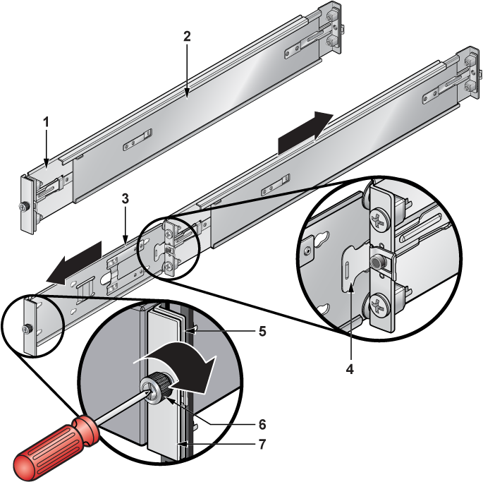
| 1 | Rail bracket (front) | 4 | Locking clip | 7 | Switch mounting ear |
| 2 | Rail bracket (rear) | 5 | Rail mounting ear | ||
| 3 | Switch bracket (for attaching to switch) | 6 | Thumb screw |
This procedure separates a bracket-rail assembly into its component pieces.
Attaching Mounting Brackets to the Chassis
The following figure displays the switch bracket alignment for mounting the switch into a four-post rack.
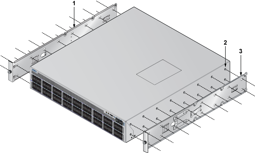
| 1 | Switch bracket | 2 | Attach point | 3 | Matching attachment hole |
This procedure attaches mounting brackets to the switch chassis, as the following figure depicts.
- Slide the bracket toward the front flange until the rail locks with an audible click.
Figure 3. Attaching the Mounting Brackets to the Switch Chassis 
1 Aligned rail 2 Seated rail To remove the mounting bracket from the chassis, lift the front edge of the mounting bracket clip with a flathead screwdriver and slide the bracket away from the front flange (opposite from the installation direction).
Expanding the Rails
The rail is initially contracted and must be expanded to attach onto the rack. This procedure expands the rails from their contracted state:
Assembling the Rails onto the Equipment Rack
- Repeat Step 1 through Step 2 for the left posts. Ensure the rails are on the same horizontal level.
Figure 4. Attaching the Rails 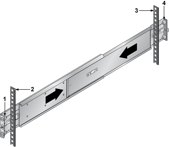
1 Front of right rail 3 Right rack post (rear) 2 Right rack post (front) 4 Rear of right rail
Attaching the Switch to the Rack
- Slide the switch on the rails toward the rear posts until the mounting bracket flanges are flush with the rail flanges attached to the rack posts.
Figure 5. Inserting the Switch onto the Rails 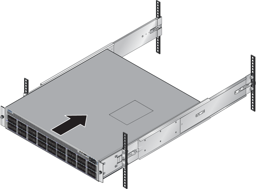
- Attach the bracket flanges to the rack post using the quick-release thumb screws supplied with the brackets.Hand-tighten the thumb screws or use a Phillips #2 screwdriver.
Note: Do not exceed a maximum torque of 20 in∙lb, nor use powered impact drivers to secure the thumb screws.
Figure 6. Attaching the Switch to the Rack Posts 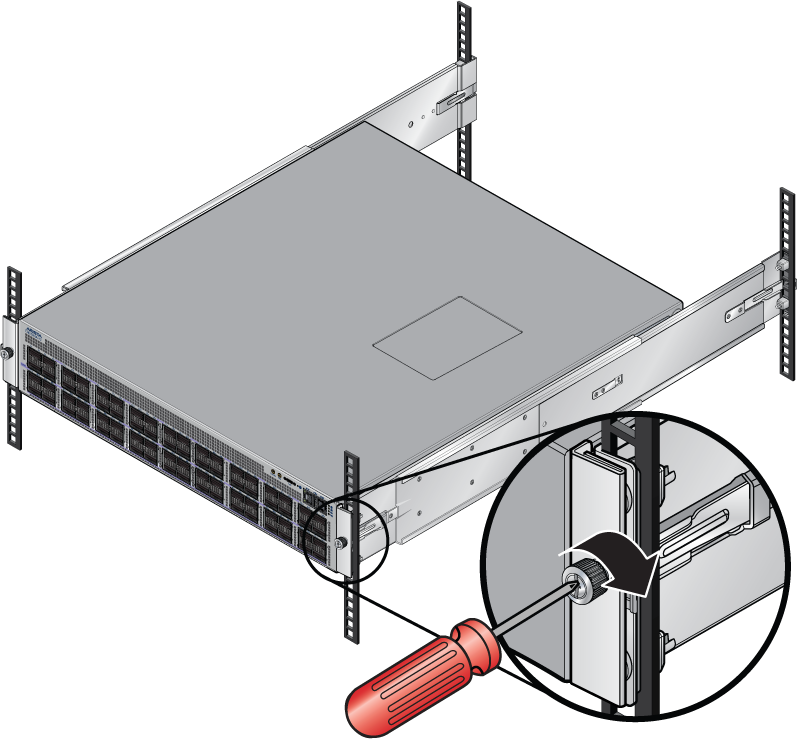
After completing the four-post rack mount, proceed to Cabling the Switch.
Rack Mounting the DCS-7720R4-128PE for Four-posts
To mount the switch to the rack, perform the following tasks.
- Insert and secure the four-post cradle to the rack Inserting and Securing the Cradle to the Racks for the Four-post DCS-DS-7720R4-128PE Mount.
- Insert and secure the switch into the rack Inserting and Securing the Switch into the Rack for the Four-post DCS-DS-7720R4-128PE Mount.
Attaching Mounting Brackets to the DCS-DS-7720R4-128PE for a Four-post Mount
The chassis includes the rack ears for mounting. The illustrations use a representative chassis.
Inserting and Securing the Cradle to the Racks for the Four-post DCS-DS-7720R4-128PE Mount
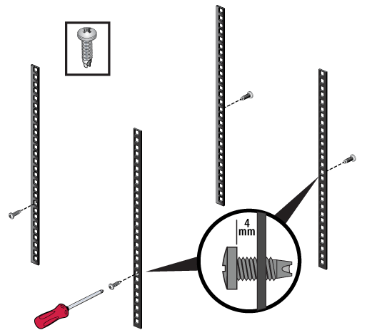
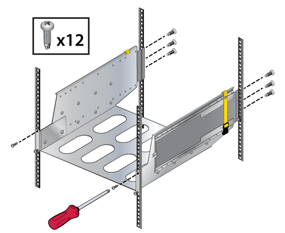
- Insert two screws loosely in the two front rack posts and two in the back two rack posts at the same level for the figure below.
Figure 7. Attaching Mounting Screws to the Rack Posts
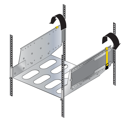
- Buckle the straps on the cradle together prior to installation so the left and right sides are angled slightly inwards, as shown in the figure below.
Figure 8. Buckling the Straps
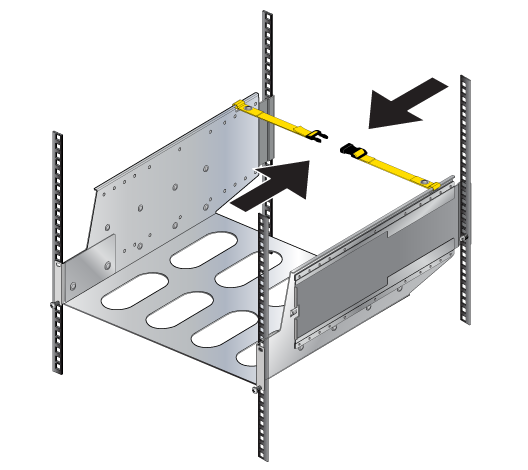
- Pull out the rear sliding rails slightly beyond the back rack posts.
- Insert the cradle so that the notches in the cradle engage behind the loosely mounted front screws for the figure below.
- Slide the rear sliding rails back in so that they are flush with the back rack posts, the notches in the cradle engage behind the loosely mounted screws, and the bottom of the cradle is horizontal and level, for the figure below.
Figure 9. Inserting the Cradle
- Release the clasp on the connector to rotate the left and right sides so they are vertical for the figure below.
Figure 10. Aligning the Cradle in the Rack
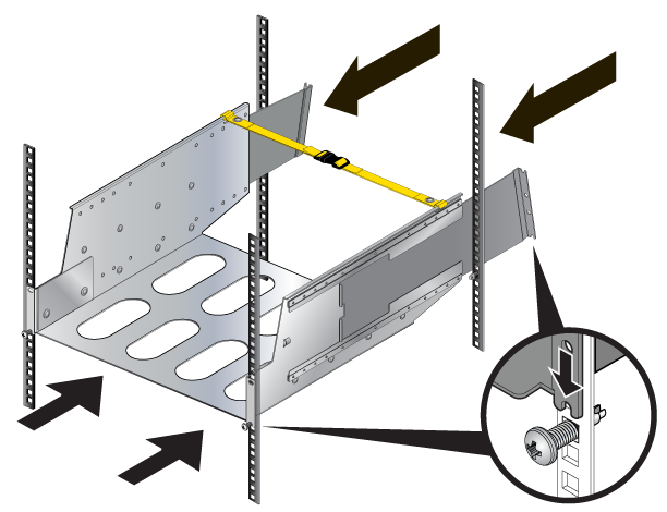
- Secure the cradle to the rack posts using the remaining screws, and tighten the loosely mounted screws for the figure below.
Figure 11. Securing the Cradle in the Rack
Inserting and Securing the Switch into the Rack for the Four-post DCS-DS-7720R4-128PE Mount
- Move the chassis to the rack using a mechanical lift.
Note: If modules are inserted in the chassis, use the lift carefully to avoid damaging any components.
- Lift the chassis into the rack and slide it into the cradle for the figure below.
Figure 12. Inserting the Chassis (Forward-Front)
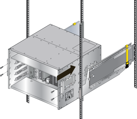
- Secure the chassis by tightening additional screws on the front flanges into the rack posts for the figure below.
After completing the Four-Post Installation, proceed to Cabling the Switch.