Configure Orchestrator Disaster Recovery
This section provides disaster recovery (DR) instructions for Orchestrator.
Orchestrator Disaster Recovery Overview
The Orchestrator Disaster Recovery (DR) feature prevents the loss of stored data and resumes Orchestrator services in the event of system or network failure.
- The recovery time objective (RTO), therefore, is dependent on explicit action by the operator to trigger promotion of the standby.
- The recovery point objective (RPO), however, is essentially zero, regardless of the recovery time, because all configuration is instantaneously replicated. Monitoring data that would have been collected during the outage is cached on the Edges and Gateways pending promotion of the standby.
Active/Standby Pair
In an Orchestrator DR deployment, two identical Orchestrator systems are configured as an active / standby pair. The operator can view the state of DR readiness through the web UI on either of the servers. Edges and Gateways are aware of both Orchestrators, and while they receive configuration changes only from the active Orchestrator, they periodically send DR heartbeats to both systems to report their view of both servers and to query the DR system status. When the operator triggers a failover, the Edges and Gateways are informed of the change in their next DR heartbeat.
DR States
From the view of an operator, and of the edges and gateways, an Orchestrator has one of four DR states:
| DR State | Description |
|---|---|
| Standalone | No DR configured. |
| Active | DR configured, acting as the primary Orchestrator server. |
| Standby | DR configured, acting as an inactive replica Orchestrator server. |
| Zombie | DR formerly configured and active but no longer acting as the active or standby. |
Run-time Operation
When DR is configured, the standby server runs in a limited mode, blocking all API calls except those related to the DR status and the DR heartbeats. When the operator invokes a failover, the standby is promoted to become fully operational as a Standalone server. The server that was formerly active is automatically transitioned to a Zombie state if it is responsive and visible from the promoted standby. In the Zombie state, management configuration services are blocked and any contact from Edges and Gateways that have not transitioned to the new active Orchestrator are redirected to the promoted server.

Set Up Orchestrator Replication
- The selected standby is put into a STANDBY_CANDIDATE state, enabling it to be configured by the active server.
- The active server is then given the address and credentials of the standby and it enters the ACTIVE_CONFIGURING state.
When a STANDBY_CONFIG_RQST is created from Active to Standby, the two servers synchronize through the state transitions.
- The Gateway time zone must be set to Etc/UTC. Use the following command to view the NTP time zone.
vcadmin@vcg1-example:~$ cat /etc/timezone Etc/UTC vcadmin@vcg1-example:~$If the time zone is incorrect, use the following commands to update the time zone.
echo "Etc/UTC" | sudo tee /etc/timezone sudo dpkg-reconfigure --frontend noninteractive tzdata - The NTP offset must be less than or equal to 15 milliseconds. Use the following command to view the NTP offset.
sudo ntpqvcadmin@vcg1-example:~$ sudo ntpq -p remote refid st t when poll reach delay offset jitter ============================================================================== *ntp1-us1.prod.v 74.120.81.219 3 u 474 1024 377 10.171 -1.183 1.033 ntp1-eu1-old.pr .INIT. 16 u - 1024 0 0.000 0.000 0.000 vcadmin@vcg1-example:~$If the offset is incorrect, use the following commands to update the NTP offset.
sudo systemctl stop ntp sudo ntpdate <server> sudo systemctl start ntp - By default, a list of NTP Servers are configured in the
/etc/ntpd.conffile. The Orchestrators on which DR need to be established must have Internet to access the default NTP Servers and ensure the time is in sync on both the Orchestrators. Customers can also use their local NTP server running in their environment to sync time.
network.public.address system property.Set Up the Standby Orchestrator
To set up Orchestrator replication, perform the following steps:
- Select Replication from the Navigation panel to display the Orchestrator Replication screen.
Figure 2. Orchestrator Replication 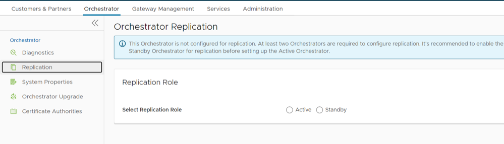
- Enable the Standby Orchestrator by selecting the Standby (Replication Role) radio button.
Figure 3. Replication Role 
- Select the Enable for Standby button.
The Prepare this Orchestrator for Standby Role dialog appears.
Figure 4. Enable for Standby 
- Select OK.
Figure 5. Standby Orchestrator 
After the Standby Orchestrator has been configured for replication, configure the Active Orchestrator. For additional information, see Set Up the Active Orchestrator.
Set Up the Active Orchestrator
To configure the second Orchestrator to be the Active Orchestrator:
- Type in the Standby Orchestrator Address and the Standby Orchestrator UUID.
The Orchestrator Address and Uuid are displayed in the Standby Orchestrator screen.
Figure 6. Orchestrator Replication 
- Select the Make Active button.
The Active Orchestrator screen displays showing a status of the current state.
Figure 7. Active Orchestrator 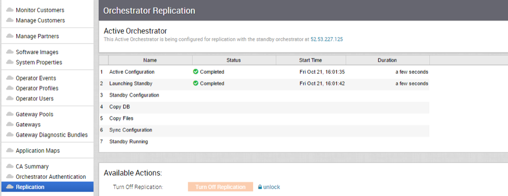
When configuration is complete, both Orchestrators (Standby and Active) will be in sync.
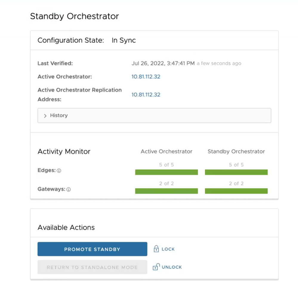
Standby Orchestrator in Sync
Figure 8. Standby Orchestrator in Sync 
You can select the toggle history link to view the status of each state.
Figure 9. Standby Orchestrator 
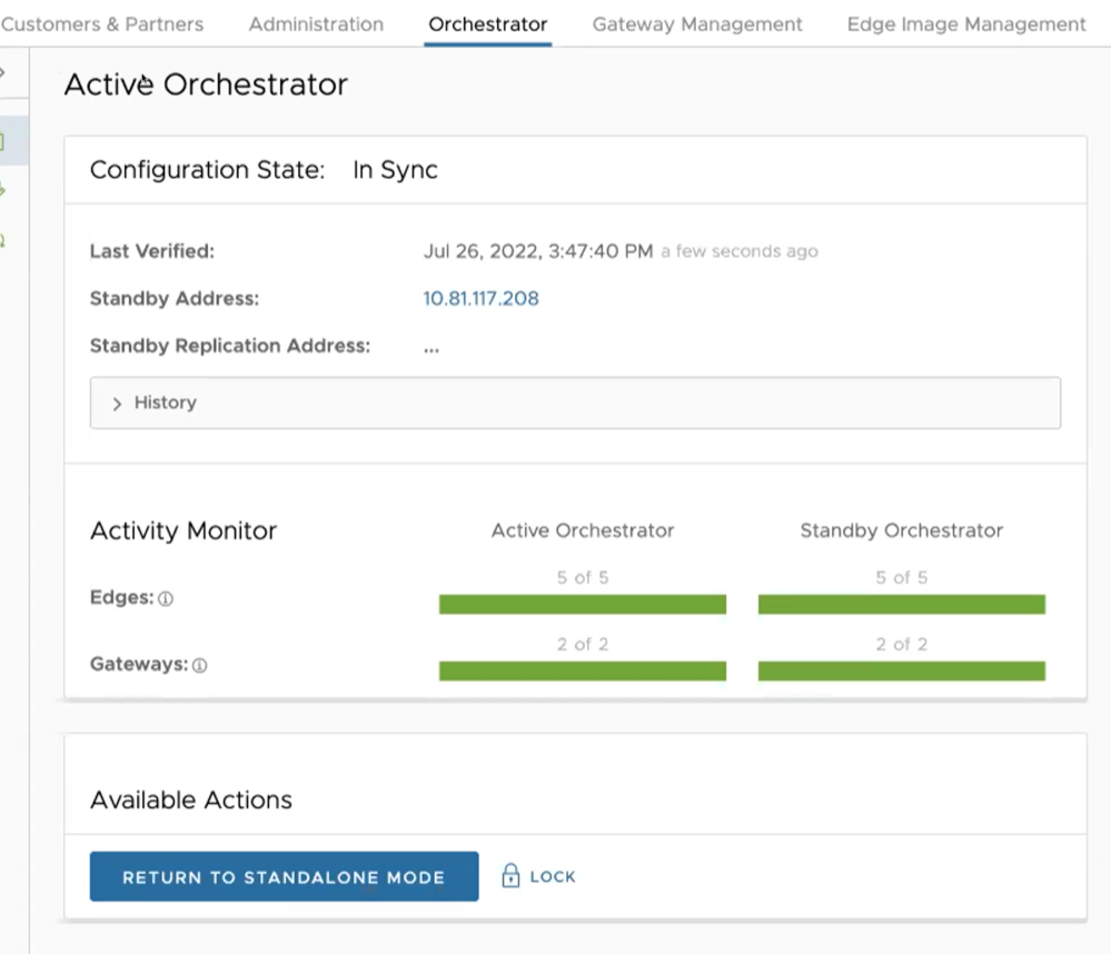
Active Orchestrator in Sync
Figure 10. Active Orchestrator in Sync 
Test Failover
The following testing failover scenarios are forced failovers for example purposes. You can perform these actions in the Available Actions area of the Active and Standby screens.
Promote a Standby Orchestrator
This section discusses how to promote a Standby Orchestrator.
- Select the unlock link.
- Select the Promote Standby button in the Available Actions area on the Standby Orchestrator screen.
Figure 11. Available Actions Tab 
The following dialog box appears, indicating that when you promote your Standby Orchestrator, administrators will no longer be able to manage the SASE Orchestrator using the previously Active Orchestrator.
Figure 12. Standby Orchestrator Dialog Box 
- Select the OK button to promote the Standby Orchestrator.
Another message dialog box appears to verify your request to promote the Standby Orchestrator. This message will appear only if the Standby Orchestrator perceives the Active Orchestrator to be in good health, meaning the Standby is communicating with the Active and duplicating data.
- Select OK to promote the Orchestrator.
Figure 13. Active Orchestrator Dialog Box 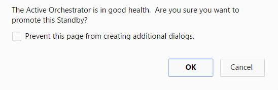
A final dialog box appears indicating that the Orchestrator is no longer a Standby and will restart in Standalone mode.
Figure 14. Standalone Mode Orchestrator Dialog Box 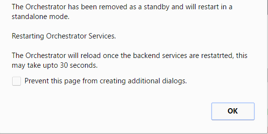
When you promote a Standby Orchestrator, it restarts in Standalone mode.
If the Standby can communicate with the formerly Active Orchestrator, it will instruct that Orchestrator to enter a Zombie state. In Zombie state, the Orchestrator communicates with its clients (edges, gateways, UI/API) that it is no longer active, and that they must communicate with the newly promoted Orchestrator. If the promoted Standby cannot communicate with the formerly Active Orchestrator, the operator should, if possible, manually demote the formerly Active Orchestrator.
Figure 15. Quiesced Orchestrator 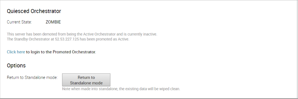
Return to Standalone Mode
To return the Zombie to standalone mode,click the Return to Standalone Mode button in the Available Actions area on the Active Orchestrator or Standby Orchestrator screens.

Troubleshooting SASE Orchestrator DR
This section discusses the failure states of the system. These are also listed in the UI, along with a more detailed description of the failure. Additional information is available in the log.
Recoverable Failures
- FAILURE_SYNCING_FILES
- FAILURE_GET_STANDBY_STATUS
- FAILURE_MYSQL_ACTIVE_STATUS
- FAILURE_MYSQL_STANDBY_STATUS
Unrecoverable Failures
- FAILURE_ACTIVE_CONFIGURING
- FAILURE_LAUNCHING_STANDBY
- FAILURE_STANDBY_CONFIGURING
- FAILURE_COPYING_DB
- FAILURE_COPYING_FILES
- FAILURE_SYNC_CONFIGURING
- FAILURE_GET_STANDBY_CONFIG
- FAILURE_STANDBY_CANDIDATE
- FAILURE_STANDBY_UNCONFIG
- FAILURE_STANDBY_PROMOTION
- FAILURE_ACTIVE_DEMOTION
Replication
The VeloCloud Orchestrator Disaster Recovery (DR) feature prevents the loss of stored data and resumes VeloCloud Orchestrator services in the event of system or network failure.
- The Recovery Time Objective (RTO), therefore, is dependent on explicit action by the operator to trigger promotion of the standby.
- The Recovery Point Objective (RPO), however, is essentially zero, regardless of the recovery time, because all configuration is instantaneously replicated. Monitoring data that would have been collected during the outage is cached on the Edges and Gateways pending promotion of the standby.
Active/Standby Pair
In a VeloCloud Orchestrator DR deployment, two identical VeloCloud Orchestrator systems are configured as an active / standby pair. The operator can view the state of DR readiness through the web UI on either of the servers. Edges and gateways are aware of both VeloCloud Orchestrators, and while they receive configuration changes only from the active VeloCloud Orchestrator, they periodically send DR heartbeats to both systems to report their view of both servers and to query the DR system status. When the operator triggers a failover, the Edges and Gateways are informed of the change in their next DR heartbeat.
DR States
From the view of an operator, and the Edges and Gateways, a VeloCloud Orchestrator has one of the following four DR states:
| DR State | Description |
|---|---|
| Standalone | No DR configured. |
| Active | DR configured, acting as the primary VeloCloud Orchestrator server. |
| Standby | DR configured, acting as an inactive replica VeloCloud Orchestrator server. |
| Zombie | DR formerly configured and active but no longer acting as the active or standby. |
Run-time Operation
When DR is configured, the standby server runs in a limited mode, blocking all API calls except those related to the DR status and the DR heartbeats. When the operator invokes a failover, the standby is promoted to become fully operational as a Standalone server. The server that was formerly active is automatically transitioned to a Zombie state if it is responsive and visible from the promoted standby. In the Zombie state, management configuration services are blocked and any contact from edges and gateways that have not transitioned to the new active VeloCloud Orchestrator are redirected to the promoted server.
Set Up VeloCloud Orchestrator Replication
- The selected standby is put into a STANDBY_CANDIDATE state, enabling it to be configured by the active server.
- The active server is then given the address and credentials of the standby and it enters the ACTIVE_CONFIGURING state.
When a STANDBY_CONFIG_RQST is made from active to standby, the two servers synchronize through the state transitions.
- The Gateway time zone must be set to Etc/UTC. Use the following command to view the NTP time zone.
vcadmin@vcg1-example:~$ cat /etc/timezone Etc/UTC vcadmin@vcg1-example:~$If the time zone is incorrect, use the following commands to update the time zone.
echo "Etc/UTC" | sudo tee /etc/timezone sudo dpkg-reconfigure --frontend noninteractive tzdata - The NTP offset must be less than or equal to 15 milliseconds. Use the following command to view the NTP offset.
sudo ntpqvcadmin@vcg1-example:~$ sudo ntpq -p remote refid st t when poll reach delay offset jitter ============================================================================== *ntp1-us1.prod.v 74.120.81.219 3 u 474 1024 377 10.171 -1.183 1.033 ntp1-eu1-old.pr .INIT. 16 u - 1024 0 0.000 0.000 0.000 vcadmin@vcg1-example:~If the offset is incorrect, use the following commands to update the NTP offset.
sudo systemctl stop ntp sudo ntpdate <server> sudo systemctl start ntp - By default, a list of NTP Servers are configured in the
/etc/ntpd.conffile. The Orchestrators on which DR need to be established must have Internet to access the default NTP Servers and ensure the time is in sync on both the Orchestrators. Customers can also use their local NTP server running in their environment to sync time.
Set Up the Standby Orchestrator
To set up the Standby Orchestrator, perform the following steps:
- In the SD-WAN service of the Enterprise Portal, select Orchestrator tab and then from the left pane select Replication button to display the Orchestrator Replication screen.
- Activate the Standby Orchestrator by selecting the Standby (Replication Role) radio button.
- Select Enable for Standby button.
Figure 18. Standby Orchestrator 
The Standby Orchestrator page appears.
- Enter the manual configuration parameters and select Update configuration info button.
After the Standby Orchestrator has been configured for replication, configure the Active Orchestrator according to the instructions below.
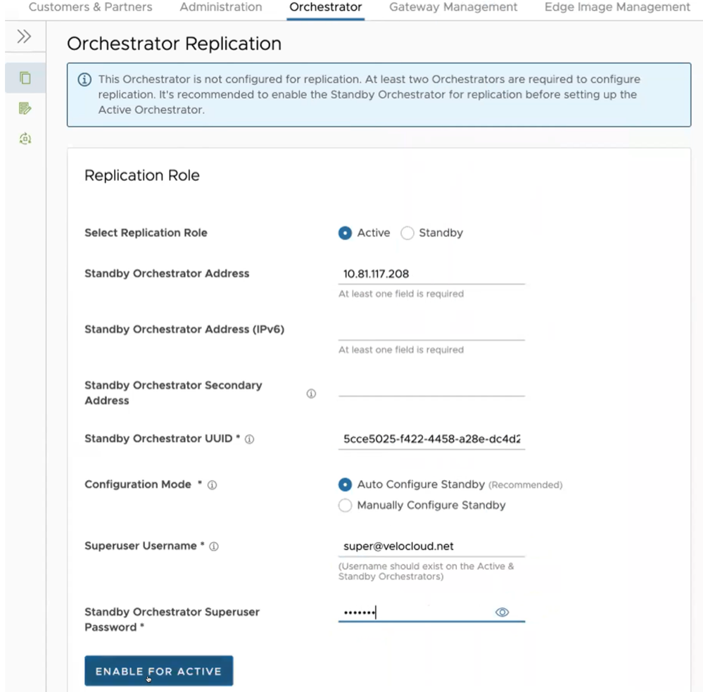
Set Up the Active Orchestrator
To set up the Active Orchestrator, select the Replication Role as Active and configure the following:
| Option | Description |
|---|---|
| Select Replication Role | Select the Active radio button for the replication role. |
| Standby Orchestrator Address | Enter the primary Standby Orchestrator IP Address. |
| Standby Orchestrator Address (IPv6) | Enter the Standby Orchestrator IPv6 Address. |
| Standby Orchestrator Secondary Address | Enter the address of the standby Orchestrator's secondary interface. This address is used for replication if the standby is promoted to active. Users can add Ipv4/Ipv6 or FQDN address here. |
| Standby Orchestrator UUID | Enter the UUID of the standby Orchestrator. |
| Configuration Mode | Select the Auto Configure Standby or Manually Configure Standby radio button based on the requirement.
When configured manually, paste a string value from ACTIVE VCO to STANDBY_WAIT . |
| Superuser Username | Enter the display name for the Orchestrator Superuser. |
| Standby Orchestrator Superuser Password | Enter the password for the Orchestrator Superuser.
Note: Starting from the 4.5 release, the use of the special character "<" in the password is no longer supported. In cases where users have already used "<" in their passwords in previous releases, they must remove it to save any changes on the page.
|
Select Enable for Active button to activate replication role.
When configuration is complete, both Orchestrators (Standby and Active) are in sync.
Standby Orchestrator in Sync
Active Orchestrator in Sync
Test Failover
The following testing failover scenarios are forced failovers for example purposes. You can perform these actions in the Available Actions area of the Active and Standbyscreens.
Promote a Standby Orchestrator
This section discusses how to promote a Standby Orchestrator.
To promote a Standby Orchestrator, perform the following steps:
- Select the unlock link.
- Select the Promote Standby button in the Available Actions area on the Standby Orchestrator screen.
Figure 22. Available Actions 
The following dialog box appears, indicating that when you promote your Standby Orchestrator, administrators can no longer be able to manage the VeloCloud Orchestrator using the previously Active Orchestrator.
Figure 23. Promote Standby Orchestrator 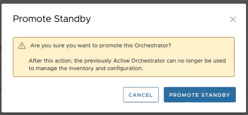
- Select the Promote Standby button to promote the Standby Orchestrator.
- Select Force Promote Standby to promote the Orchestrator.
Figure 24. Force Promote Standby Orchestrator 
A final dialog box appears indicating that the Orchestrator is no longer a Standby and restarts in Standalone mode.
Figure 25. Orchestrator Removed Status 
When you promote a Standby Orchestrator, it restarts in Standalone mode.
If the Standby can communicate with the formerly Active Orchestrator, it instructs that Orchestrator to enter a Zombie state. In Zombie state, the Orchestrator communicates with its clients (edges, gateways, UI/API) that it is no longer active, and that they must communicate with the newly promoted Orchestrator. If the promoted Standby cannot communicate with the formerly Active Orchestrator, the operator should, if possible, manually demote the formerly Active Orchestrator.

Return to Standalone Mode
To return the Zombie to standalone mode, select the Return to Standalone Mode button in the Available Actions area on the Active Orchestrator or Standby Orchestrator screens.

vco.disasterRecovery.zombie.expirySeconds, which is defaulted to 1800 seconds.Troubleshooting VeloCloud Orchestrator DR
This section describes the failure states of the system. These are also listed in the UI, along with a more detailed description of the failure. Additional information is available in the Arista log.
Recoverable Failures
- FAILURE_SYNCING_FILES
- FAILURE_GET_STANDBY_STATUS
- FAILURE_MYSQL_ACTIVE_STATUS
- FAILURE_MYSQL_STANDBY_STATUS
Unrecoverable Failures
- FAILURE_ACTIVE_CONFIGURING
- FAILURE_LAUNCHING_STANDBY
- FAILURE_STANDBY_CONFIGURING
- FAILURE_COPYING_DB
- FAILURE_COPYING_FILES
- FAILURE_SYNC_CONFIGURING
- FAILURE_GET_STANDBY_CONFIG
- FAILURE_STANDBY_CANDIDATE
- FAILURE_STANDBY_UNCONFIG
- FAILURE_STANDBY_PROMOTION
- FAILURE_ACTIVE_DEMOTION