Connecting Serial and Management Cables
This section discusses the following topics:
Connecting the Supervisor Cables
The supervisor module contains the console, management, and USB ports. The following figure displays port locations on the DCS-7368-SUP-D switch supervisor card.
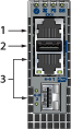
| 1 | Console Port (Serial) | 2 | USB Port | 3 | Ethernet Management Ports |
-
Console (Serial) Port: Connect to a PC with RJ-45 to DB-9 serial adapter cable. Default switch settings include:
- 9600 baud
- No flow control
- 1 stop bit
- No parity bits
- 8 data bits
- Ethernet management port: Connect to 10/100/1000 management network with RJ-45 cable.
- Ethernet management port (optical): Connect to 1 Gbit management network with SFP connector module and cable.
Figure 2. SFP Port Module Insertion 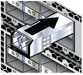
Connect cables as required to line card module ports. Supervisor and line card module ejectors on the front of the chassis assist with cable management.
Important:Excessive bending can damage interface cables, especially optical cables.
Flexion excessive peut endommager les câbles d'interface, en particulier les câbles optiques.
- USB Port: This may be used for software or configuration updates.
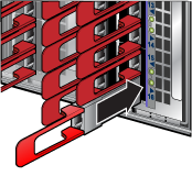
Connecting the Linecard Modules and Cables
Install required QSFP28, QSFP-DD, and OSFP optic modules in linecard module ports.
Note: In some devices, adjacent QSFP ports may require you to rotate the module for insertion.
Note: For more information about supported optical transceivers, refer to
https://www.arista.com/assets/data/pdf/Transceiver-Guide.pdf.
Warning: Excessive bending can damage interface cables, especially optical cables.