Front Panel
This section displays the front panel of all switches this guide covers.
Note: Depending on the components used to populate the chassis, the appearance of a specific switch may differ.
Note: Linecard slot numbering starts with '3'. When installing the linecards start at the lowest, begin with blanks.
Note: All switches are designed to fit in 19-inch racks.
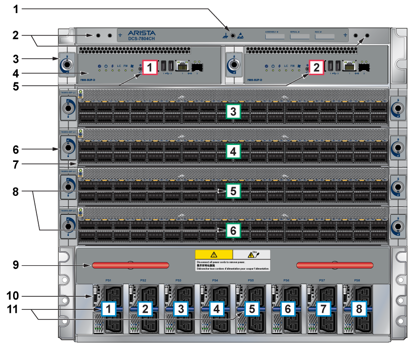
| 1 | ESD attach point | 2 | Grounding locations | 3 | Supervisor lock |
| 4 | Supervisor modules | 5 | Supervisor slot number | 6 | Linecard lock |
| 7 | Linecard | 8 | Linecard slot numbers | 9 | Extraction tool |
| 10 | Power supplies | 11 | Power supplies slot numbers |
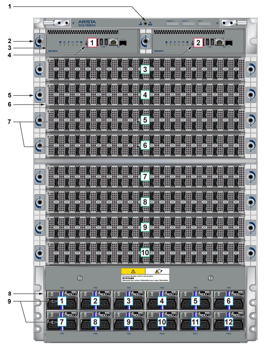
| 1 | ESD attach point | 2 | Supervisor lock | 3 | Supervisor modules |
| 4 | Supervisor slot numbers | 5 | Linecard lock | 6 | Linecard |
| 7 | Linecard slot numbers | 8 | Power supplies | 9 | Power supplies slot numbers |
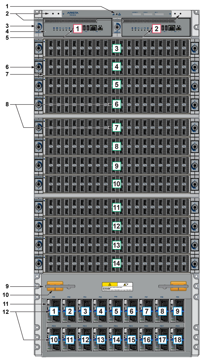
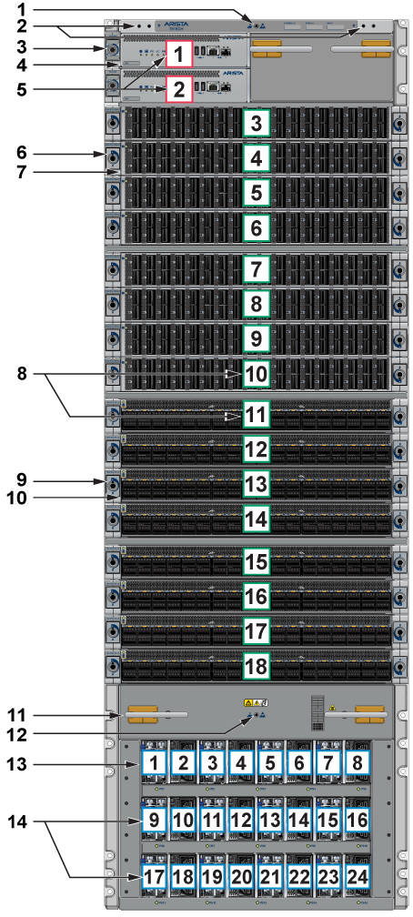
| 1 | ESD attach point | 2 | Grounding locations | 3 | Supervisor lock |
| 4 | Supervisor modules | 5 | Supervisor slot numbers | 6 | Linecard lock |
| 7 | Linecard | 8 | Linecard slot numbers | 9 | Extraction tool |
| 10 | Linecard and Supervisor extraction tool tether | 11 | Power supplies | 12 | Power supplies slot numbers |
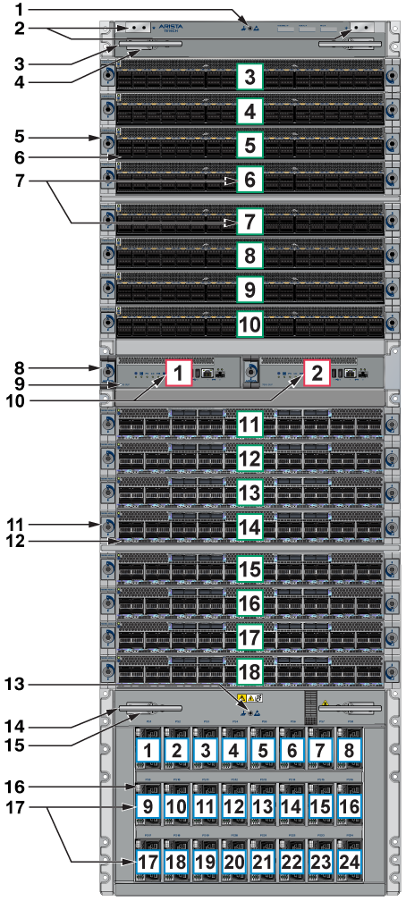
| 1 | ESD attach point | 2 | Grounding locations | 3 | Extraction tool |
| 4 | Linecard and Supervisor extraction tool tether | 5 | Linecard lock | 6 | Linecard |
| 7 | Linecard slot number | 8 | Supervisor lock | 9 | Supervisor modules |
| 10 | Supervisor slot numbers | 11 | Linecard lock | 12 | Linecard |
| 13 | ESD attach point | 14 | Extraction tool | 15 | Linecard and Supervisor extraction tool tether |
| 16 | Power supplies | 17 | Power supplies slot numbers |
| 1 | ESD attach point | 2 | Grounding locations | 3 | Supervisor lock |
| 4 | Supervisor module | 5 | Supervisor slot numbers | 6 | Linecard lock |
| 7 | Linecard | 8 | Linecard slot numbers | 9 | Linecard lock |
| 10 | Linecard | 11 | Extraction tool | 12 | ESD attach point |
| 13 | Power supplies | 14 | Power supplies slot numbers |