Preparation
Site Selection
The following criteria should be considered when selecting a site to install the switch:
• Temperature and Ventilation: For proper ventilation, install the switch where there is ample airflow to the front and back of the switch. The ambient temperature should not go below 0° or exceed 40° C.
Important! To prevent the switch from overheating, do not operate it in an area where the ambient temperature exceeds 40°C (104°F).
• Airflow Orientation: Determine the airflow direction of the four fan modules and two power supply modules on the rear panel. Figure 2-1 indicates the location of the airflow direction label on the power supply modules. The fan module airflow direction label is located on the left side of the handle. The fan and power supply module handles also indicate the module airflow direction:
• Blue Handle: Air Inlet module.
• Red Handle: Air Exit module.
Verify that each module has the same airflow direction. Base the switch orientation on the airflow direction of the modules to assure the air inlet is always oriented toward the cool aisle:
• Air Exit Modules: orient the rear panel toward the hot aisle.
• Air Inlet Modules: orient the rear panel toward the cool aisle.
If the airflow direction is not compatible with the installation site, contact your sales representative to obtain modules that circulate air in the opposite direction.
• Rack Space: Install the switch in a 19" rack or cabinet. The switch height is 1 RU. The accessory kit provides mounting brackets for two-post and four-post racks.
When mounting the switch in a partially filled rack, load the rack from bottom to top, with the heaviest equipment at the bottom. Load the switch at the bottom if it is the only item in the rack.
• Power Requirements: The switch requires one 100-240 VAC, 50 or 60 Hz, 5.29 A circuit. Two circuits provide redundancy protection. The switch uses power cables that comply with IEC-320 and have a C13 plug. The accessory kit provides two IEC-320 C13 to C14 power cables (two meters).
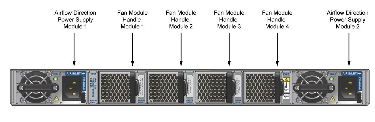
Figure 2-1: Airflow Direction Labels
Important! The power input plug-socket combination must be accessible at all times; it provides the primary method of disconnecting power from the system.
• Other Requirements: Select a site where liquids or objects cannot fall onto the equipment and foreign objects are not drawn into the ventilation holes. Verify these guidelines are met:
• Clearance areas to the front and rear panels allow for unrestricted cabling.
• All front and rear panel indicators can be easily read.
• AC power cords can reach from the AC power outlet to the connector on the rear panel.
Important! All power connections must be removed to de-energize the unit.
Tools Required for Installation
The following tools and equipment are required to install the switch:
• Phillips #1 screwdriver.
• Phillips #3 screwdriver.
• Four screws (two-post rack mount) that fit the equipment rack.
• Eight screws (four-post rack mount) that fit the equipment rack.
The accessory kit does not include screws for attaching the switch to the equipment rack. When installing the switch into an equipment rack with unthreaded post holes, nuts are also required to secure the switch to the rack posts.
Electrostatic Discharge (ESD) Precautions
Observe these guidelines to avoid ESD damage when installing or servicing the switch.
• Assemble or disassemble equipment only in a static-free work area.
• Use a conductive work surface (such as an antistatic mat) to dissipate static charge.
• Wear a conductive wrist strap to dissipate static charge accumulation.
• Minimize handling of assemblies and components.
• Keep replacement parts in their original static-free packaging.
• Remove all plastic, foam, vinyl, paper, and other static-generating materials from the work area.
• Use tools that do not create ESD.