Cabling the Modular Switch
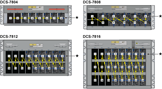
Cabling the Power Supplies
Before you begin, refer to the Arista Networks document Compliance and Safety Guide, available at product-documentation.
| Switch | Order |
|---|---|
| DCS-7804 | 8, 7, 6, 5, 4, 3, 2, 1 |
| DCS-7808 | 6, 12, 5, 11, 4, 10, 3, 9, 2, 8, 1, 7 |
| DCS-7812 | 9, 18, 8, 17, 7, 16, 6, 15, 5, 14, 4, 13, 3, 12, 2, 11, 1, 10 |
| DCS-7816 | 8, 16, 24, 7, 15, 23, 6, 14, 22, 5, 13, 21, 4, 12, 20, 3, 11, 19, 2, 10, 18, 1, 9, 17 |
The following figure shows the recommended order. A blank (X) should be placed on all unpopulated bays.
Power down the switch. Remove all power cords from the power inlets.
Mettez le commutateur: Retirez tous les cordons d'alimentation des prises d'alimentation.
The installation of this equipment must comply with local and national electrical codes. Consult with the appropriate regulatory agencies and inspection authorities to ensure compliance if necessary.
Installation de cet équipement doit être conformes aux codes électriques locaux et nationaux. Si nécessaire, consulter les organismes de réglementation appropriés et des autorités de contrôle pour assurer la conformité.
Many configurations will require additional power supplies.
Nombreuses configurations exigera des alimentations supplémentaires.
All power supply slots must be filled with either a power supply or blank to ensure proper airflow.
Tous les emplacements d'approvisionnement de puissance doivent être remplis avec une alimentation ou vide pour assurer un débit d'air appropriée.
Read all installation instructions before connecting the system to the power source.
Lire toutes les instructions d'installation avant de brancher le système à la source d'alimentation.
Power Supply Configurations show each switch's minimum number of operating power supplies connected to active circuits.
Each power supply includes a fan that maintains proper power supply temperature. The appendices display the location of components for all switches described in this guide.
Cabling Chassis Ground
Identify the location of the chassis grounding locations on the front panel of the switches. Additional grounding locations are on the rear panel of the switch chassis. After mounting the switch into the rack, connect at least one of the chassis grounds to the data center ground using two-hole ground lugs with 16 mm (5/8 in.) spacing and two M4 x 0.7 screws. After the switch is grounded, ESD wrist straps can be grounded by connecting them to one of the attach points.
Grounding wires and grounding lugs are not supplied. Wire size should meet local and national installation requirements. Commercially available 2 or 4 AWG wire is recommended for installations in the U.S.
À la terre et de mise à la terre fils cosses ne sont pas fournis. Calibre des fils doit satisfaire des exigences de l'installation locale et nationale. Disponible dans le commerce 2 ou 4 AWG fil est recommandé pour les installations aux États-Unis.
This equipment must be grounded. Never defeat the ground conductor. This unit requires over-current protection.
Cet équipement doit être mis à la terre. Ne jamais modifier le conducteur de terre. Cet appareil nécessite de protection contre les surintensités.
Secondary Grounding wires, lugs, and screws (M4 x 0.7) are not supplied.
Secondaire à la terre, câbles, cosses et vis (M4 x 0.7) ne sont pas fournis.
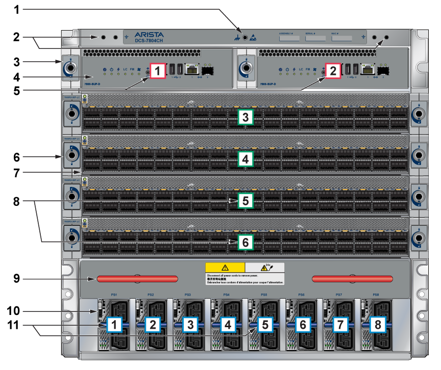
| 1 | ESD attach point | 2 | Grounding locations | 3 | Supervisor lock |
| 4 | Supervisor modules | 5 | Supervisor slot number | 6 | Linecard lock |
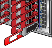
| 7 | Linecard | 8 | Linecard slot numbers | 9 | Extraction tool |
| 10 | Power supplies | 11 | Power supplies slot numbers |
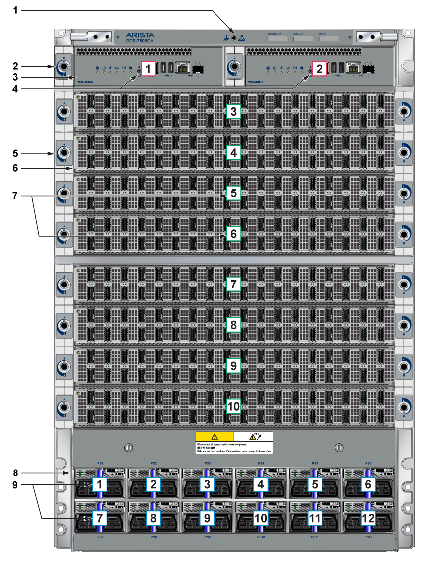
| 1 | ESD attach point | 2 | Supervisor lock | 3 | Supervisor modules |
| 4 | Supervisor slot numbers | 5 | Linecard lock | 6 | Linecard |
| 7 | Linecard slot numbers | 8 | Power supplies | 9 | Power supplies slot numbers |
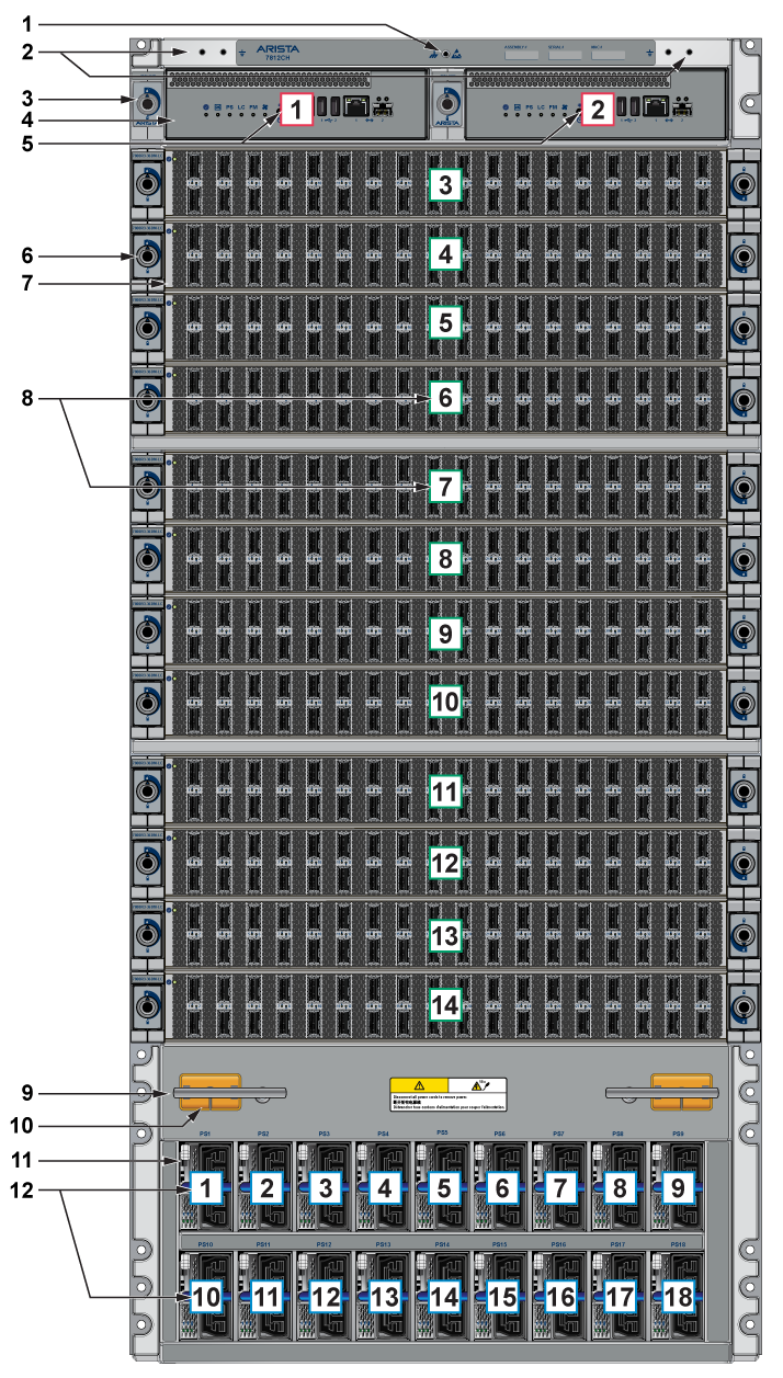
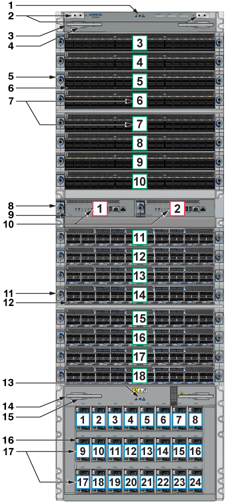
| 1 | ESD attach point | 2 | Grounding locations | 3 | Supervisor lock |
| 4 | Supervisor modules | 5 | Supervisor slot numbers | 6 | Linecard lock |
| 7 | Linecard | 8 | Linecard slot numbers | 9 | Extraction tool |
| 10 | Linecard and Supervisor extraction tool tether | 11 | Power supplies | 12 | Power supplies slot numbers |
| 1 | ESD attach point | 2 | Grounding locations | 3 | Extraction tool |
| 4 | Linecard and Supervisor extraction tool tether | 5 | Linecard lock | 6 | Linecard |
| 7 | Linecard slot number | 8 | Supervisor lock | 9 | Supervisor modules |
| 10 | Supervisor slot numbers | 11 | Linecard lock | 12 | Linecard |
| 13 | ESD attach point | 14 | Extraction tool | 15 | Linecard and Supervisor extraction tool tether |
| 16 | Power supplies | 17 | Power supplies slot numbers |
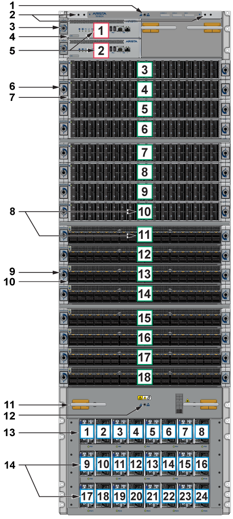
| 1 | ESD attach point | 2 | Grounding locations | 3 | Supervisor lock |
| 4 | Supervisor module | 5 | Supervisor slot numbers | 6 | Linecard lock |
| 7 | Linecard | 8 | Linecard slot numbers | 9 | Linecard lock |
| 10 | Linecard | 11 | Extraction tool | 12 | ESD attach point |
| 13 | Power supplies | 14 | Power supplies slot numbers |
Cabling the AC Power Supplies
The switches use PWR-D1-3041-AC-BLUE (Figure 7) power supplies with SAF-D-GRID connectors on the PSU inputs. Power cables are included with the accessory kit (Table 1). To power the switch, insert the other side of the cable into the main power-providing circuit.
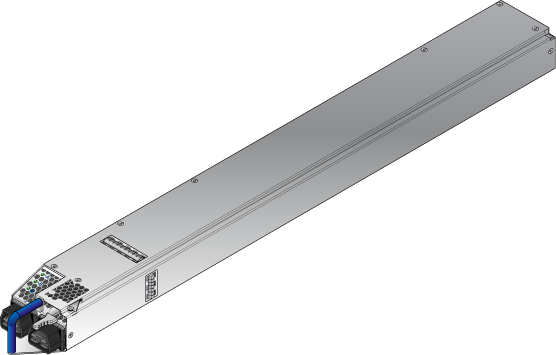
The Front Panel displays the front panel location of the power supplies.
- The LEDs on a PSU remain lit even after you disconnect the power and remove the PSU from the chassis. They will eventually turn off in a short while.
- The PWR-D1-3041-AC-BLUE PSU uses 2x 220 V supply inputs and uses 2 APP SAF-D-GRID 400 connectors.
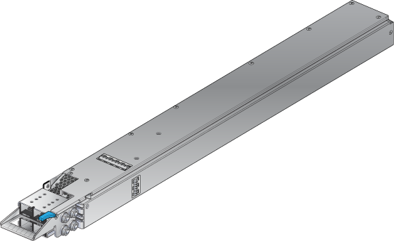
Cabling the DC Power Supply
The -48V and Battery-Return leads are a pair and should run adjacent and be approximately the same length.
Le - 48V et câbles de batterie-retour sont une paire courir à côté de l'autre et doivent être à peu près la même longueur.
DC Power Supplies
The switches support the PWR-D2-3041-DC-BLUE DC power supply displayed in Figure 8.
Wire and Lug Preparation
- Shrink the tubing with a heat gun.
Figure 9. Lugs Wiring Terminations 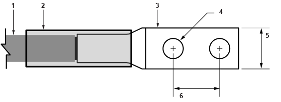
1 Insulated wire 3 Lug 5 Half-inch width 2 Heat-shrink tubing 4 Quarter-inch diameter hole 6 Five-eighth-inch apart centers
Power Supply Specifications
The Table 2 shows the power supply specifications for each of the PSUs supported.
| Power Supply | Maximum Output Power Rating (DC) | Input Voltage and Frequency | Maximum Input Current | Input Branch Circuit Protection |
|---|---|---|---|---|
| PWR-D1-3041-AC-BLUE | 3000 W | 200 to 240 VAC(nominal) 50/60 Hz (nominal) | 2x 16 A | 2x 20 A |
| PWR-D2-3041-DC-BLUE | 3000 W | -48 V to -60 VDC, 70 A to 55A | 2x 70 A | 2x 90 A |
Each power supply requires input branch circuit protection in compliance with AHJ requirements.
Chaque alimentation nécessite une protection du circuit de la branche d’entrée conformément aux exigences de l’AHJ.
Power Supply Configurations
The following table shows the power supply configurations for the modular switches.
| Modular Switch | Number of PSUs Shipped in Bundle | Maximum Number of PSUs Supported |
|---|---|---|
| DCS-7804 | 6 | 8 |
| DCS-7808 | 8 | 12 |
| DCS-7812 | 10 | 18 |
| DCS-7816 | 12 | 24 |
Recommendations for Power Supply Usage
- Use separate circuits (A and B) to protect each power supply.
- When replacing a failed PSU, use the same PSU model. If the original model is no longer supported or available, an alternative PSU must be approved before use.
- Only mix power supply types if your switch allows mixing power supplies.
- To minimize distribution power loss, use an equal number of supplies in each row (e.g., 4 PSUs in slots 1-4 and 4 PSUs in slots 7-10 for a configuration with 8 PSUs for the DCS-7808 switch). Cabling the Power Supplies provides more details.
Note: The DCS-7808 switch can house PSUs in either of two rows. The LEDs for PSUs in each row indicate correct status only after at least one of the PSUs in that row (PSU1 to PSU6 or PSU7 to PSU12) is energized from a power source. For the DCS-7812 and DCS-7816 switches, all PSU LEDs will report status correctly as long as one PSU is powered.
- All power supply slots must be filled with a powered supply, a blank (X), or a non-powered power supply.
- Valid redundancy configurations for each domain are described in Power Supply Redundancy.
Power Supply Redundancy
The installation of this equipment must comply with local and national electrical codes. Consult with the appropriate regulatory agencies and inspection authorities to ensure compliance if necessary.
Installation de cet équipement doit être conformes aux codes électriques locaux et nationaux. Si nécessaire, consulter les organismes de réglementation appropriés et des autorités de contrôle pour assurer la conformité.
Read all installation instructions before connecting the system to the power source.
Lire toutes les instructions d'installation avant de brancher le système à la source d'alimentation.
Most installations will have redundant, dual, independent power feeds. Each independent power feed will be referenced as A and B.
The recommended installation is to wire input_A and input_B of each supply to an independent power feed (A or B).
Each power supply includes a fan that maintains proper power supply temperature. The appendices display the location of the components on all switches described in this guide.
The Front Panel displays the front panel location of the supervisor modules, linecards, and PSUs.
The Rear Panel displays the rear panel location of fabric modules.
This unit requires over-current protection.
Cet appareil nécessite de protection contre les surintensités.
Unused slots must be occupied or covered with a blank to ensure proper airflow through the chassis.
Les emplacements inutilisés doivent être occupés ou recouvert d'un blanc pour assurer la bonne circulation d'air dans le châssis.
Connecting Supervisor Cables
Supervisor modules contain console, management, and USB ports. Figure 10 display port and status LED locations on the supervisors. For additional information about the serial port, refer to the chassis specification in Figure 11.
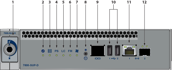
| 1 | Locking mechanism | 5 | Linecard status LED | 9 | RJ-45 Serial management port |
| 2 | Supervisor status LED | 6 | Fabric Module status LED | 10 | USB Ports |
| 3 | Supervisor active status LED | 7 | Fan status LED | 11 | RJ-45 Ethernet management port |
| 4 | PSU status LED | 8 | Clock In | 12 | SFP Ethernet management port |
- Console (Serial) Port: Connect to a PC with RJ-45 to DB-9 serial adapter cable. Default switch settings include:
- 9600 baud
- No flow control
- 1 stop bit
- No parity bits
- 8 data bits
The appropriate supervisor cards must be installed in one of the designated slots. They are shown in Figure 11 for the DCS-7808 switch. For the DCS-7816 switch, the supervisor slots are in the middle of the chassis.
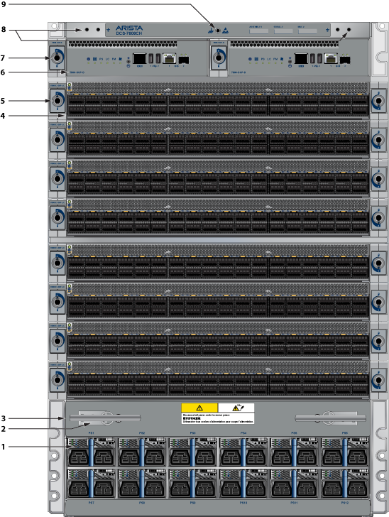
| 1 | Power supplies | 4 | Linecards | 7 | Supervisor lock |
| 2 | Linecard and Supervisor extraction tool tether | 5 | Linecard lock | 8 | Grounding locations |
| 3 | Extraction tool | 6 | Supervisor modules | 9 | ESD attach point |
RJ-45 to DB-9 Connections
| RJ-45 | DB-9 | RJ-45 | DB-9 | ||||
|---|---|---|---|---|---|---|---|
| RTS | 1 | 8 | CTS | GND | 5 | 5 | GND |
| DTR | 2 | 6 | DSR | RXD | 6 | 3 | TXD |
| TXD | 3 | 2 | RXD | DSR | 7 | 4 | DTR |
| GND | 4 | 5 | GND | CTS | 8 | 7 | RTS |
- Ethernet management port: Connect to 10/100/1000 management network with RJ-45 cable.
- USB Port: This may be used for software or configuration updates.
- Clock Input Port: The port type is MCX connector, 2-5.5V, 50 ohm termination.
Connecting Linecard Modules and Cables
Install required SFP, SFP+, QSFP+, QSFP100, OSFP, and QSFP-DD optic modules in linecard module ports (Figure 12).
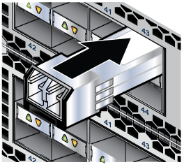
Connect cables as required to linecard module ports. Supervisor and linecard module ejectors on the front of the chassis assist with cable management.
https://www.arista.com/assets/data/pdf/Transceiver-Guide.pdf.
Excessive bending can damage interface cables, especially optical cables.
Flexion excessive peut endommager les câbles d'interface, en particulier les câbles optiques.