IPv6
Introduction
Routing transmits network layer data packets over connected independent subnets. Each subnet is assigned an IP address range and each device on the subnet is assigned an IP address from that range.
Connected subnets have IP address ranges that do not overlap. A router is a network device connecting multiple subnets. Routers forward inbound packets to the subnet whose address range includes the packets’ destination address.
IPv4 and IPv6 are Internet layer protocols that define packet-switched inter-networking, including source-to-destination datagram transmission across multiple networks. The switch supports IP version 4 (IPv4) and IP version 6 (IPv6).
IPv6 is described by RFC 2460: Internet Protocol, Version 6 (IPv6) Specification. RFC 2463 describes ICMPv6 for IPv6. ICMPv6 is a core protocol of the Internet Protocol suite.
IPv6 Description
Internet Protocol version 6 (IPv6) consists ofa communications protocol used for relaying network packets across a set of connected networks using the Internet Protocol suite. eos assigns a 128 bit IP address that identifies its network location to each network device.
IPv6 Address Format
- Leading zeros in each 16-bit number may be omitted.
- One set of consecutive 16-bit numbers that equal zero may be replaced by a double colon.
Example
d28e:0000:0000:0000:0234:812f:61ed:4419
d28e:0:0:0:234:812f:61ed:4419
d28e::234:812f:61ed:4419
IPv6 addresses typically denote a 64-bit network prefix and a 64-bit host address.
Unicast and Anycast Addressing
Unicast addressing defines a one-to-one association between the destination address and a network endpoint. Each destination address uniquely identifies a single receiver endpoint. Anycast addressing defines a one-to-one-of-many association, for example, packets to a single member of a group of potential receivers identified by the same destination address.
- A 64-bit network prefix that identifies the network segment.
- A 64-bit interface identifier based on interface MAC address.
- Global address - Valid in all networks and connect with other addresses with global scope anywhere or to addresses with link-local scope on the directly attached network.
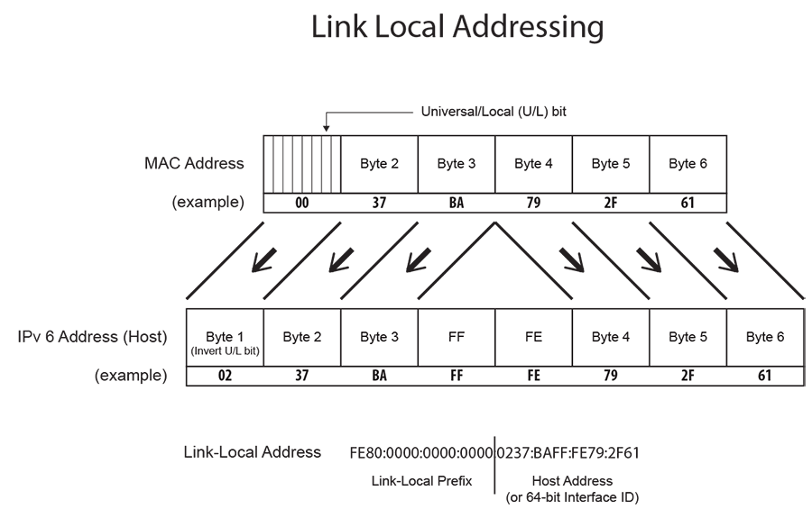
- Link-local address - Scope extends only to the link to which the interface is directly connected. Link-local addresses do not route from the link.
The switch creates the link-local addresses and you cannot configure it. The following figure depicts the switch’s link local address derivation method.
Multicast Addressing
Multicast addressing defines a one-to-many association. Packets simultaneously route from a single sender to multiple endpoints in a single transmission. The network replicates packets as required by network links that contain a recipient endpoint. eos assigns one multicast address to an interface for each multicast group of an interface.
A solicited-node multicast address consists of an IPv6 multicast address whose scope extends only to the link to the directly connected interface. All IPv6 hosts have at least one address per interface. Neighbor Discovery Protocol uses solicited-node multicast addresses to obtain Layer 2 link-layer addresses of other nodes.
IPv6 DHCP Snooping
Dynamic Host configuration Protocol (DHCP) snooping is a Layer 2 feature that is configured on LAN switches. The Arista eos switch supports Option-37 insertion that allows relay agents to provide remote-id information in DHCP request packets. DHCP servers use this information to determine the originating port of DHCP requests and associate a corresponding IP address to that port. DHCP servers use port information to track host location and IP address usage by authorized physical ports.
DHCP snooping uses the information option (Option-37) to include the switch MAC address (router-id) along with the physical interface name and VLAN number (remote-id) in DHCP packets. After adding the information to the packet, the DHCP relay agent forwards the packet to the DHCP server as specified by the DHCP protocol.
Neighbor Discovery Protocol
- Auto-configuring a node IPv6 address.
- Sensing other nodes on the link.
- Discovering the link-local addresses of other nodes on the link.
- Detecting duplicate IPv6 addresses.
- Discovering available routers.
- Discovering DNS servers
- Discovering the link address prefix.
- Maintaining path reachability data to other active neighbor nodes.
- Router Solicitation
- Router Advertisement
- Neighbor Solicitation
- Neighbor Advertisement
- Redirect
IPv6 Duplicate Address Detection Proxy
Overview
IPv6 Duplicate Address Detection Proxy ensures that all IPv6 addresses assigned on a network segment are unique. After a host verifies the uniqueness of the IPv6 address, it enables DAD on the network.
However, if two network segments cannot communicate with each other, IPv6 DAD cannot perform and duplicate addresses may be assigned to the same interface. To prevent this, a proxy for IPv6 hosts must be assigned on the network and it responds on behalf of the address owner when the address already exists.
Configuring IPv6
Configuring IPv6 on the Switch
Configure IPv6 to route unicast packets, perform static routing, and Equal Cost Multi-path routing on a switch. This section covers the following topics:
Enabling IPv6 Unicast Routing on the Switch
The ipv6 unicast-routing command enables the forwarding of IPv6 unicast packets. When routing is enabled, the switch attempts to deliver inbound packets to destination addresses by forwarding them to interfaces or next hop addresses specified by the IPv6 routing table.
Example
switch(config)# ipv6 unicast-routing
switch(config)#
Configuring Default and Static IPv6 Routes
The ipv6 route command creates an IPv6 static route to a destination with an IPv6 prefix, and the source uses an IPv6 address or a routable interface port. When multiple routes exist to a destination prefix, the route with the lowest administrative distance takes precedence.
y default, eos assigns an administrative distance of1 to static routes.
Assigning a higher administrative distance to a static route allows dynamic routing data to override the static route. For example, an OSPF intra-area route, with a default distance of 110, overrides a static route with a distance value of 200.
Example
switch(config)# ipv6 route 10:23:31:00:01:32:93/24 vlan 300
switch(config)#
The default route denotes the packet forwarding rule that takes effect if no other route exists for a specified IPv6 address. eos sends all packets without destinations in the routing table to the destination specified by the default route.
The IPv6 default route source uses ::/0 as an IP address. eos refers to the default route destination as the default gateway.
Example
switch(config)# ipv6 route ::/0 fd7a:629f:52a4:fe61::2
switch(config)#
Configuring Link-Local Next Hop Autodiscovery for IPv6 Static Routes
IPv6 static routes support link-local next hop addresses on point-to-point interfaces, but in deployments that rely on Zero Touch Provisioning (ZTP) to activate switches with static routes, specifying link-local addresses in configuration templates becomes challenging. Link-Local addresses vary per switch and interface and does not allow the use of a single template across multiple deployments.
eos supports automatic discovery of link-local next-hop using the IPv6 Router Advertisements to discover the neighbor link-local address and use it as the next-hop for the static routes. Configuring this feature enables simpler and more scalable ZTP deployment and eliminates the need to specify link-local addresses in configuration templates.
Use the following command to enable automatic link-local next-hop discovery on a specified point-to-point interface, Ethernet 1:
switch(config)# ipv6 route 2001:db8:100::/6 next-hop auto p2p Ethernet1
switch(config)#
IPv6 ECMP
Multiple routes configured to the same destination with the same administrative distance comprise an Equal Cost Multi-Path (ECMP) route. The switch spreads outbound traffic across all ECMP route paths equally and assigns the same tag value to each path. Commands that change the tag value of any ECMP path change the tag value of all paths in the ECMP.
Resilient ECMP is available for IPv6 routes. Equal Cost Multipath Routing (ECMP) and Load Sharing describes resilient ECMP. The ipv6 hardware fib ecmp resilience command implements IPv6 resilient ECMP.
Example
switch(config)# ipv6 hardware fib ecmp resilience 2001:db8:0::/64 capacity 5 redundancy 3
switch(config)#
Configuring IPv6 on an Interface
This section covers the following topics:
Enabling IPv6 on an Interface
The ipv6 enable command enables IPv6 in the configuration Mode if it does not have a configured IPv6 address. It also configures the interface with an IPv6 address.
The no ipv6 enable command disables IPv6 on an interface not configured with an IPv6 address. This command does not disable interfaces configured with an IPv6 address.
Example
switch(config)# interface vlan 200
switch(config-vl200)# ipv6 enable
switch(config-vl200)#
Assigning an IPv6 Address to an Interface
The ipv6 address command enables IPv6 in the Interface configuration Mode, assigns a global IPv6 address to the interface, and defines the prefix length. Routable interfaces support this command. Multiple global IPv6 addresses can be assigned to an interface. eos supports Stateless Address Auto configuration (SLAAC).
Examples
- Use the following commands to configure an IPv6 address with subnet mask for
vlan
200:
switch(config)# interface vlan 200 switch(config-if-Vl200)# ipv6 address 10:23:31::1:32:93/64 switch(config-if-Vl200)# - Use the following commands to configure an IPv6 address using
SLAAC:
switch(config)#interface vlan 200
switch(config-if-vl200)#ipv6 address auto-config
switch(config-if-vl200)#
IPv6 Neighbor Discovery
- Determine Layer 2 addresses for neighbors known to reside on attached links.
- Detect changed Layer 2 addresses.
- Purge invalid values from the neighbor cache table.
- Find neighboring routers to forward packets.
- Track neighbor reachability status.
The RFC 2461 defines IPv6 Neighbor Discovery. IPv6 Stateless Address Autoconfiguration is described by RFC 2462.
The following sections describe Neighbor Discovery configuration tasks.
Reachable Time
The ipv6 nd reachable-time command specifies the time period that eos includes in the reachable time field of Router Advertisements (RAs) sent from the configuration mode interface. The reachable time defines the period that a remote IPv6 node becomes reachable after a reachability confirmation event.
Example
switch(config)# interface vlan 200
switch(config-if-Vl200)# ipv6 nd reachable-time 25000
switch(config-if-Vl200)# show active
   interface Vlan200
   ipv6 address fd7a:4321::1/64
   ipv6 nd reachable-time 25000
switch(config-if-Vl200)#
Router Advertisement Interval
The ipv6 nd ra interval command configures the interval between IPv6 RA transmissions from the configuration mode interface.
Example
switch(config)# interface vlan 200
switch(config-if-Vl200)# ipv6 nd ra interval 60
switch(config-if-Vl200)# show active
interface Vlan200
   ipv6 nd ra interval 60
switch(config-if-Vl200)#
Router Lifetime
The ipv6 nd ra lifetimecommand specifies the value eos places in therouter lifetime field of IPv6 RAs sent from the IPv6 interface.
If you configure the value as 0, IPv6 peers connected to the specified interface remove the switch from the lists of default routers. Values greater than 0 indicate the time in seconds that peers should keep the router on their default router lists without receiving further RAs from the switch. Unless set to 0, the router lifetime value should be equal to or exceed the interval between unsolicited RAs sent on the interface.
Example
switch(config)# interface vlan 200
switch(config-if-Vl200)# ipv6 nd ra lifetime 2700
switch(config-if-Vl200)# show active
interface Vlan200
   ipv6 nd ra lifetime 2700
switch(config-if-Vl200)#
Router Advertisement Prefix
The ipv6 nd prefix command configures neighbor discovery router advertisement prefix inclusion for RAs sent from the configuration mode interface.
By default, all prefixes configured as IPv6 addresses are advertised in the interface’s RAs. The ipv6 nd prefix command with the no-advertise option prevents advertising of the specified prefix without affecting the advertising of other prefixes specified as IPv6 addresses. When an interface configuration includes at least one ipv6 nd prefix command that enables prefix advertising, RAs advertise only prefixes specified through ipv6 nd prefix commands.
Commands enabling prefix advertising also specify the advertised valid and preferred lifetime periods. Default periods are 2,592,000 (valid) and 604,800 (preferred) seconds.
Example
switch(config)# interface vlan 200
switch(config-if-Vl200)# ipv6 nd prefix 3012:D678::/64 1296000
switch(config-if-Vl200)#
Router Advertisement Suppression
The ipv6 nd ra disabled command suppress IPv6 RA transmissions on the configuration mode interface. By default, only unsolicited RAs that are transmitted periodically are suppressed. The all option configures the switch to suppress all RAs, including those responding to a router solicitation.
Example
switch(config)# interface vlan 200
switch(config-vl200)# ipv6 nd ra disabled all
switch(config-vl200)#
Router Advertisement MTU Suppression
The ipv6 nd ra mtu suppress command suppresses the router advertisement MTU option on the IPv6 interface. The MTU option causes an identical MTU value to advertise from all nodes on a link. By default, eos does not suppress the router advertisement MTU option.
Example
switch(config)# interface vlan 200
switch(config-vl200)# ipv6 nd ra mtu suppress
switch(config-vl200)#
Router Advertisement Flag configuration
- The ipv6 nd managed-config-flag command sets the managed address configuration flag. This bit instructs hosts to use stateful address autoconfiguration.
- The ipv6 nd other-config-flag command sets the other stateful configuration flag. This bit indicates availability of autoconfiguration information, other than addresses. Hosts should use stateful autoconfiguration when available. The setting of this flag has no effect if the managed address configuration flag is set.
- These commands configure the switch to set the managed address
configuration flag in advertisements sent from
interface vlan
200.
switch(config)# interface vlan 200 switch(config-if-Vl200)# ipv6 nd managed-config-flag switch(config-if-Vl200)# - These commands configure the switch to set the other stateful
configuration flag in advertisements sent from
interface vlan
200.
switch(config)# interface vlan 200
switch(config-if-Vl200)# ipv6 nd other-config-flag
switch(config-if-Vl200)#
IPv6 Router Preference
The IPv6 Router Preference protocol supports an extension to RA messages for communicating default router preferences and more specific routes from routers to hosts. This provides assistance to hosts when selecting a router. RFC 4191 describes the IPv6 Router Preference Protocol.
The ipv6 nd router-preference command specifies the value that the switch enters in the Default Router Preference (DRP) field of RAs sent from the IPv6 interface. The default field entry value is medium.
Example
switch(config)# interface vlan 200
switch(config-if-Vl200)# ipv6 nd router-preference medium
switch(config-if-Vl200)#
Configuring uRPF
Unicast Reverse Path Forwarding (uRPF) verifies the accessibility of source IP addresses in forwarded packets from the switch. Unicast Reverse Path Forwarding (uRPF) describes uRPF. Enable uRPF for IPv6 packets entering the IPv6 interface using the ipv6 verify command.
- Strict Mode -uRPF verifies that a packet received on the interface has a routing table entry specified for a return packet.
- Loose Mode - uRPF validation does not consider the inbound packet ingress interface only that a valid return path exists.
Example
switch(config)# interface vlan 100
switch(config-if-Vl100)# ipv6 verify unicast source reachable-via rx allow-default
switch(config-if-Vl100)# show active
 interface Vlan100
   ipv6 verify unicast source reachable-via rx allow-default
switch(config-if-Vl100)#
Configuring IPv6 Duplicate Address Detection Proxy on an Interface
Configure IPv6 DAD on an interface, and add an IPv6 address on the interface. Then enable IPv6 on the interface. You can configure this in conjunction with IPv6 ND Proxy.
Example configuration
Use the following commands on interface Ethernet 1:
switch(config-if-Et1/1#ipv6 nd dad proxy
switch(config-if-Et1/1#ipv6 address 2001:db8:1::/64
switch(config-if-Et1/1#ipv6 enableswitch(config-if-Et1/1#ipv6 nd cache expire 1800Displaying IPv6 DAD Proxy Information
switch#show ipv6 nd dad interface
 Ethernet1
 ipv6 nd proxy prefix connected
 ipv6 nd dad proxy
 ipv6 address 2001:db8:3::/64
Displaying IPv6 Network Components
Displaying RIB Route Information
Use the show rib route ipv6 command to view the IPv6 Routing Information Base (RIB) information.
Example
switch# show rib route ipv6 bgp
VRF name: default, VRF ID: 0xfe, Protocol: bgp
Codes: C - Connected, S - Static, P - Route Input
       B - BGP, O - Ospf, O3 - Ospf3, I - Isis
       > - Best Route, * - Unresolved Nexthop
       L - Part of a recursive route resolution loop
 B    2001:10:1::/64 [200/42]
         via 2001:10:1::100 [0/1]
            via Ethernet1, directly connected
>B    2001:10:100::/64 [200/200]
         via 2001:10:1::100 [0/1]
            via Ethernet1, directly connected
>B    2001:10:100:1::/64 [200/0]
         via 2001:10:1::100 [0/1]
            via Ethernet1, directly connected
>B    2001:10:100:2::/64 [200/42]
         via 2001:10:1::100 [0/1]
            via Ethernet1, directly connected

switch#
Displaying the FIB and Routing Table
The show ipv6 route command displays routing table entries in the Forwarding Information Base (FIB), including static routes, routes to directly connected networks, and dynamically learned routes. Multiple equal cost paths to the same prefix display contiguously as a block, with the destination prefix displayed only on the first line.
Example
switch> show ipv6 route fd7a:3418:52a4:fe18::/64
IPv6 Routing Table - 77 entries
Codes: C - connected, S - static, K - kernel, O - OSPF, B - BGP, R - RIP, A -
Aggregate

O   fd7a:3418:52a4:fe18::/64 [10/20]
     via f180::21c:73ff:fe00:1319, Vlan3601
     via f180::21c:73ff:fe00:1319, Vlan3602
     via f180::21c:73ff:fe00:1319, Vlan3608
     via f180::21c:73ff:fe0f:6a80, Vlan3610
     via f180::21c:73ff:fe00:1319, Vlan3611

switch>
Displaying the Route Age
The show ipv6 route age command displays the IPv6 route age to the specified IPv6 address or prefix.
Example
switch> show ipv6 route 2001::3:0/11 age
IPv6 Routing Table - 74 entries
Codes: C - connected, S - static, K - kernel, O - OSPF, B - BGP, R - RIP, A -
Aggregate

C 2001::3:0/11 age 00:02:34
switch>
Displaying Host Routes
- F - Displays static routes from the FIB.
- R - Displays routes defined because the IP address is an interface address.
- A - Displays routes to any neighboring host with the switch that has an ARP entry.
Example
switch# show ipv6 route host
R - receive F - FIB, A - attached

 F  ::1 to cpu
 A  fee7:48a2:0c11:1900:400::1 on Vlan102
 R  fee7:48a2:0c11:1900:400::2 to cpu
 F  fee7:48a2:0c11:1a00::b via fe80::21c:73ff:fe0b:a80e on Vlan3902
 R  fee7:48a2:0c11:1a00::17 to cpu
 F  fee7:48a2:0c11:1a00::20 via fe80::21c:73ff:fe0b:33e on Vlan3913
 F  fee7:48a2:0c11:1a00::22 via fe80::21c:73ff:fe01:5fe1 on Vlan3908
                            via fe80::21c:73ff:fe01:5fe1 on Vlan3902

switch#
Displaying Route Summaries
The show ipv6 route summary command displays the current number of routes of the IPv6 routing table in summary format.
Example
switch> show ipv6 route summary
Route Source    Number Of Routes
------------------ ----------------
   connected                      2
   static                         0
   ospf                           5
   bgp                            7
   isis                           0
   internal                       1
   attached                       0
   aggregate                      2

   Total Routes                   17
switch>
TCP MSS Clamping for IPv6
TCP MSS Clamping limits the value of the Maximum Segment Size (MSS) in the TCP header of TCP SYN packets transiting a specified Ethernet or tunnel interface. Setting the MSS ceiling can avoid IP fragmentation in tunnel scenarios by ensuring that the MSS is low enough to account for the extra overhead of GRE and tunnel outer IP headers. Use TCP MSS Clamping when connecting through a GRE tunnel to cloud providers that require asymmetric routing.
When configuring MSS clamping on an interface, if the TCP MSS value in a SYN packet transiting that interface exceeds the configured ceiling limit, the configured limit overwrites the TCP MSS value, and the TCP checksum recomputes and updates.
By default, the software datapath handles TCP MSS Clamping. However, the hardware configuration can support the process to minimize possible packet loss and reduce the number of TCP sessions that the switch can establish per second.
Configuring the TCP MSS Ceiling on an IPv6 Interface
Set the TCP MSS Ceiling limit on an interface using command tcp mss ceiling ipv6. This also enables TCP MSS Clamping on the switch.
- This command works only on egress packets.
- Unicast packets entering the switch support TCP MSS Ceiling and the configuration has no effect on GRE transit packets
- or GRE decap, even if the egress interface has TCP MSS Ceiling configured.
- eos does not support TCP MSS Ceiling on L2 (switchport) interfaces.
- VXLAN, Loopback or management interfaces do not support TCP MSS Ceiling.
- Only hardware TCP MSS clamping is supported on release eos-4.26.1F and later.
switch(config)# interface ethernet 26
switch(config-if-Et5)# no switchport
switch(config-if-Et5)# tcp mss ceiling ipv6 1436 egress
switch(config-if-Et5)#
IPv6 Commands
Global configuration Commands
Interface configuration Commands
- ipv6 address
- ipv6 enable
- ipv6 nd dad proxy
- ipv6 nd managed-config-flag
- ipv6 nd ns-interval
- ipv6 nd other-config-flag
- ipv6 nd prefix
- ipv6 nd ra dns-server
- ipv6 nd ra dns-servers lifetime
- ipv6 nd ra dns-suffix
- ipv6 nd ra dns-suffixes lifetime
- ipv6 nd ra hop-limit
- ipv6 nd ra interval
- ipv6 nd ra lifetime
- ipv6 nd ra mtu suppress
- ipv6 nd ra disabled
- ipv6 nd ra rx accept default-route
- ipv6 nd reachable-time
- ipv6 nd router-preference
- ipv6 verify
- pim ipv6 sparse-mode
- ipv6 dhcp snooping
Privileged EXEC Commands
EXEC Commands
- show ipv6 dhcp relay counters
- show ipv6 dhcp snooping counters
- show ipv6 dhcp snooping hardware
- show ipv6 hardware fib aggregate-address
- show ipv6 interface
- show ipv6 nd dad proxy
- show ipv6 nd ra internal state
- show ipv6 neighbors
- show ipv6 route
- show ipv6 route age
- show ipv6 route host
- show ipv6 route interface
- show ipv6 route match tag
- show ipv6 route summary
- show platform fap mroute ipv6
- show rib route ipv6
clear ipv6 dhcp relay counters
The clear ipv6 dhcp relay counters command resets the DHCP relay counters. If you do not specify a port, the command clears the counters for the switch and for all interfaces. Otherwise, the command clears the counter for the specified interface.
Command Mode
Privileged EXEC
Command Syntax
clear ipv6 dhcp relay counters [port]
Parameters
- no parameter - Removes all dynamic entries.
- interface ethernet e_num - Specify the Ethernet interface by e_num.
- interface loopback l_num - Specify the Loopback interface by l_num.
- interface port-channel p_num - Specify the Port-channel interface by p_num p_num.
- interface vlan v_num - Specify the VLAN interface by v_num.
Example
switch(config)# show ipv6 dhcp relay counters

          |  Dhcp Packets  |
Interface | Rcvd Fwdd Drop |         Last Cleared
----------|----- ---- -----|---------------------
  All Req |  376  376    0 | 4 days, 19:55:12 ago
 All Resp |  277  277    0 |
          |                |
Ethernet4 |  207  148    0 | 4 days, 19:54:24 ago


switch(config)# interface ethernet 4
switch(config-if-Et4)# clear ipv6 dhcp relay counters

          |  Dhcp Packets  |
Interface | Rcvd Fwdd Drop |         Last Cleared
----------|----- ---- -----|---------------------
  All Req |  380  380    0 | 4 days, 21:19:17 ago
 All Resp |  281  281    0 |
          |                |
Ethernet4 |    0    0    0 |4 days, 21:18:30 ago
These commands clear all DHCP relay counters on the switch.
switch(config-if-Et4)# exit

switch(config)# clear ipv6 dhcp relay counters

switch(config)# show ipv6 dhcp relay counters
          |  Dhcp Packets  |
Interface | Rcvd Fwdd Drop | Last Cleared
----------|----- ---- -----|-------------
  All Req |    0    0    0 |  0:00:03 ago
 All Resp |    0    0    0 |
          |                |
Ethernet4 |    0    0    0 | 0:00:03 ago
switch(config)#
clear ipv6 dhcp snooping counters
The clear ipv6 dhcp snooping counters command resets the DHCP snooping packet counters.
Command Mode
Privileged EXEC
Command Syntax
clear ipv6 dhcp snooping counters [counter_type]
- counter_type - Specifies the type of counter to reset.
- no parameter - Clears the counters for each VLAN.
-
debug - Clears aggregate counters and drop cause counters.
- This command clears the number of DHCP packets sent and received on each
VLAN.
switch# clear ipv6 dhcp snooping counters switch# show ipv6 dhcp snooping counters | Dhcpv6 Request Pkts | Dhcpv6 Reply Pkts | Vlan | Rcvd Fwdd Drop | Rcvd Fwdd Drop | Last Cleared -----|------ ------ -------|------ ----- ------|------------- 2789 | 1 1 0 | 1 1 0 | 0:03:09 ago - This command clears the number of DHCP packets sent on the
switch.
switch# clear ipv6 dhcp snooping counters debug
switch# show ipv6 dhcp snooping counters debug

Counter                       Snooping to Relay Relay to Snooping
----------------------------- ----------------- -----------------
Received                                      1                 1
Forwarded                                     1                 1
Dropped - Invalid VlanId                      0                 0
Dropped - Parse error                         0                 0
Dropped - Invalid Dhcp Optype                 0                 0
Dropped - Invalid Remote-ID Option            0                 0
Dropped - Snooping disabled                   0                 0

Last Cleared:  0:04:29 ago
clear ipv6 neighbors
The clear ipv6 neighbors command removes the specified dynamic IPv6 neighbor discovery cache entries. Commands that do not specify an IPv6 address remove all dynamic entries for the listed interface. Commands that do not specify an interface remove all dynamic entries.
Command Mode
Privileged EXEC
Command Syntax
clear ipv6 neighbors [port][dynamic_ipv6]
- port Interface through which neighbor is accessed. Options
include the following:
- no parameter - Removes all dynamic entries.
- interface ethernet e_num - Specify the Ethernet interface by e_num.
- interface loopback l_num - Specify the Loopback interface by l_num.
- interface port-channel p_num - Specify the Port-channel interface by p_num p_num.
- interface vlan v_num - Specify the VLAN interface by v_num.
- dynamic_ipv6 - Specifies the address of entry to remove.
Options include the following:
- no parameter - Removes all dynamic entries for specified interface.
- ipv6_addr - Removes the IPv6 address of the entry.
Example
switch# clear ipv6 neighbors vlan 200
switch#
ipv6 address
The ipv6 address command assigns a global IPv6 address to the IPv6 interface, and defines the prefix length. Routable interfaces support this command. Multiple global IPv6 addresses can be assigned to an interface. The IPv6 address or prefix can be supplied manually, or configured using Stateless Address Auto configuration.
The no ipv6 address and default ipv6 address commands remove the IPv6 address assignment from the configuration mode interface by deleting the corresponding ipv6 address command from running-config. If the command does not include an address, all address assignments are removed from the interface. IPv6 remains enabled on the interface after the removal of all IPv6 addresses only ifipv6 enable command is configured on the interface.
Command Mode
Interface-Ethernet configuration
Interface-Loopback configuration
Interface-management configuration
Interface-Port-channel configuration
Interface-VLAN configuration
Command Syntax
ipv6 address [ ipv6_address | ipv6_prefix | auto-config ]
no ipv6 address { ipv6_address | ipv6_prefix | auto-config }
default ipv6 address { ipv6_address | ipv6_prefix | auto-config }
Parameter
ipv6_address - Specify the IPv6 address to assign to the interface.
ipv6_prefix - Specify the IPv6 prefix assigned to the interface (CIDR notation).
auto-config - Use SLAAC auto-configuration.
Example
switch(config)# interface vlan 200
switch(config-if-Vl200)# ipv6 address 10:23:31:00:01:32:93/64
switch(config-if-Vl200)#
ipv6 dhcp relay always-on
The iv6p dhcp relay always-on command enables the switch DHCP relay agent on the switch regardless of the DHCP relay agent status on any interface. By default, the DHCP relay agent is enabled only if at least one routable interface is configured with an ipv6 dhcp relay destination statement.
The no ipv6 dhcp relay always-on and default ipv6 dhcp relay always-on commands remove the ipv6 dhcp relay always-on command from running-config.
Command Mode
Global configuration
Command Syntax
ipv6 dhcp relay always-on
no ipv6 dhcp relay always-on
default ipv6 dhcp relay always-on
Exampleswitch(config)# ipv6 dhcp relay always-on
switch(config)#ipv6 dhcp relay destination
The ipv6 dhcp relay destination command enables the DHCPv6 relay agent and sets the destination address on the configuration mode interface.
The no ipv6 dhcp relay destination and default ipv6 dhcp relay destination commands remove the corresponding ipv6 dhcp relay destination command from running-config. When the commands do not list an IPv6 address, all ipv6 dhcp relay destination commands are removed from running-config.
Command Mode
Interface-Ethernet configuration
Interface-Port-channel configuration
Interface-VLAN configuration
Command Syntax
ipv6 dhcp relay destination [ipv6_addr][source-address ipv6_addr]
no ipv6 dhcp relay destination [ipv6_addr]
default ipv6 dhcp relay destination [ipv6_addr]
- ipv6_addr DCHP Server’s IPv6 address.
- source-address ipv6_addr specify the source IPv6 address to communicate with DHCP server.
Guidelines
If the source-address parameter is specified, then the DHCP client receives an IPv6 address from the subnet of source IP address. The source-address must be one of the configured addresses on the interface.
Example
This command enables the DHCPv6 relay agent and sets the destination address to 2001:0db8:0:1::1 on interface ethernet 4.
switch(config)# interface ethernet 4
switch(config-if-Et4)# ipv6 dhcp relay destination 2001:0db8:0:1::1
switch(config-if-Et4)# show ip dhcp relay
DHCP Relay is active
DHCP Relay Option 82 is disabled
DHCPv6 Relay Link-layer Address Option (79) is disabled
DHCP Smart Relay is disabled
Interface: Ethernet4
  DHCP Smart Relay is disabled
  DHCP servers: 1::1
                2001:db8:0:1::1
switch(config-if-Et4)#
ipv6 dhcp relay option link-layer address
The ipv6 dhcp relay option link-layer address command enables the DHCPv6 relay agent to configure the client link layer address option to solicit and request messages. In other words, the command enables the link layer address option (79) in the global configuration mode.
The no ipv6 dhcp relay option link-layer address command disables the link layer address option (79) in the global configuration mode.
Command Mode
Global configuration
Command Syntax
ipv6 dhcp relay option link-layer address
no ipv6 dhcp relay option link-layer address
default ipv6 dhcp relay option link-layer address
Example
switch(config)# ipv6 dhcp relay option link-layer addressipv6 dhcp relay option remote-id
The ipv6 dhcp relay option command configures DHCPv6 Relay Option 37, Remote-ID, to add the MAC address, interface ID or name, and hostname as the remote-id format. The no version of the command removes the configuration from the running-config.
Command Mode
Global configuration
Command Syntax
ipv6 dhcp relay option remote-id format {%m:%h:%p | %m:%i | %m:%p}
no ipv6 dhcp relay option remote-id format {%m:%h:%p | %m:%i | %m:%p}
Parameters
- remote-id - Add Option 37 to the DHCP Relay configuration.
- format - Select one of the following as the format for the remote-id:
- %m:%h:%p - Specify the MAC address, hostname, and interface name as the remote-id.
- %m:%i - Specify the MAC address and interface ID as the remote-id.
- %m:%p - Specify the MAC address and interface name as the remote-id.
Example
Use the following command to specify using the MAC address, hostname, and interface name for the Remote-ID:
switch(config)# ipv6 dhcp relay option remote-id format %m:%h:%p ipv6 enable
The ipv6 enable command enables IPv6 on the configuration mode interface. Assigning an IPv6 address to an interface also enables IPv6 on the interface.
The no ipv6 enable and default ipv6 enable command remove the corresponding ipv6 enable command from running-config. This action disables IPv6 on interfaces that are not configured with an IPv6 address.
Command Mode
Interface-Ethernet configuration
Interface-Loopback configuration
Interface-management configuration
Interface-Port-channel configuration
Interface-VLAN configuration
Command Syntax
ipv6 enable
no ipv6 enable
default ipv6 enable
Example
switch(config)# interface vlan 200
switch(config-vl200)# ipv6 enable
switch(config-vl200)#
ipv6 hardware fib aggregate-address
The ipv6 hardware fib aggregate-address command specifies the routing table repository of specified IPv6 route.
By default, routes that are created statically through the CLI or dynamically through routing protocols are initially stored in software routing tables, then entered in the hardware routing table by the routing agent. This command prevents the entry of the specified route into the hardware routing table. Specified routes that are in the hardware routing table are removed by this command. Specific routes that are encompassed within the specified route prefix are affected by this command.
The no ipv6 hardware fib aggregate-address and default ipv6 hardware fib aggregate-address commands remove the restriction from the hardware routing table for the specified routes by removing the corresponding ipv6 hardware fib aggregate-address command from running-config.
Command Mode
Global configuration
Command Syntax
ipv6 hardware fib aggregate-address ipv6_prefix summary-only software-forward
no ipv6 hardware fib aggregate-address ipv6_prefix
default ipv6 hardware fib aggregate-address ipv6_prefix
Parameters
ipv6_prefix IPv6 prefix that is restricted from the hardware routing table (CIDR notation).
Example
switch(config)# ipv6 hardware fib aggregate-address fd77:4890:5313:ffed::/64
summary-only software-forward
switch(config)# show ipv6 hardware fib aggregate-address
Codes: S - Software Forwarded
S  fd77:4890:5313:ffed::/64

switch(config)#
ipv6 hardware fib ecmp resilience
The ip hardware fib ecmp resilience command configures a fixed number of next hop entries in the hardware ECMP table for the specified IPv6 address prefix. In addition to specifying the maximum number of next hop addresses that the table can contain for the prefix, the command introduces a redundancy factor that allows duplication of each next hop address. The fixed table space for the address is the maximum number of next hops multiplied by the redundancy factor.
The default method of adding or removing next hop entries when required by the active hashing algorithm leads to inefficient management of the ECMP table, which can result in the rerouting of packets to different next hops that breaks TCP packet flows. Implementing fixed table entries for a specified IP address allows data flows that are hashed to a valid next hop number to remain intact. Additionally, traffic is evenly distributed over a new set of next hops.
The no ip hardware fib ecmp resilience and default ip hardware fib ecmp resilience commands restore the default hardware ECMP table management by removing the ip hardware fib ecmp resilience command from running-config.
Command Mode
Global configuration
Command Syntax
ipv6 hardware fib ecmp resilience net_prfx capacity nhop_max redundancy duplicates
no ipv6 hardware fib ecmp resilience net_addr
default ipv6 hardware fib ecmp resilience net_addr
- net_prfx IPv6 address prefix managed by command.
- nhop_max Specifies maximum number of nexthop
entries for specified IP address prefix. Value range varies by platform:
- Helix: <2 to 64>
- trident: <2 to 32>
- trident II: <2 to 64>
- duplicates Specifies the redundancy factor. Value ranges from 1 to 128.
Example
switch(config)# ipv6 hardware fib ecmp resilience 2001:db8:0::/64 capacity 5 redundancy 3ipv6 hardware fib nexthop-index
The ipv6 hardware fib nexthop-index command deterministically selects the next hop used for ECMP routes. By default, routes that are created statically through the CLI or dynamically through routing protocols are initially stored in software routing tables, then entered in the hardware routing table by the routing agent. This command specifies the method of creating an index-offset number that points to the next hop from the list of the route’s ECMP next hops.
- Next hop index: specified in the command.
- Prefix offset: the least significant bits of the route’s prefix.
The command specifies the number of bits that comprise the prefix offset. The prefix offset is set to the prefix when the command specifies a prefix size larger than the prefix. If the command specifies an prefix size of zero, the prefix-offset is also zero and the index-offset is set to the next hop index.
When the index-offset is greater than the number of next hops in the table, the position of the next hop is the remainder of the division of the index-offset by the number of next hop entries.
The no ipv6 hardware fib nexthop-index and default ipv6 hardware fib nexthop-index commands remove the specified nexthop used for ECMP routes by removing the ipv6 hardware fib nexthop-index command from running-config.
Command Mode
Global configuration
Command Syntax
ipv6 hardware fib nexthop nxthop_index [PREFIX]
no ipv6 hardware fib nexthop
default ipv6 hardware fib nexthop
- nxthop_index specifies the next hop index. Value ranges from 0 to 32.
- PREFIX Number of bits of the route’s prefix to
use as the prefix-offset. Value ranges from 0 to
64.
- no parameter The prefix offset is set to zero.
- prefix-bits 0 to 64 Specifies the number bits to use as the prefix-offset.
Example
switch(config)# ipv6 hardware fib nexthop-index 5 prefix-bits 10

switch> show ip
IP Routing : Enabled
IP Multicast Routing : Disabled
VRRP: Configured on 0 interfaces

IPv6 Unicast Routing : Enabled
IPv6 ECMP Route support : False
IPv6 ECMP Route nexthop index: 5
IPv6 ECMP Route num prefix bits for nexthop index: 10
switch>
ipv6 hardware fib optimize prefixes
The ipv6 hardware fib optimize prefixes command in the Global configuration Mode reserves IPv6 optimized prefixes on the default and non-default VRFs.
The no version of the command explicitly removes the configuration from the running-config on the switch.
Command Mode
Global configuration
Command Syntax
ip hardware fib optimize vrf vrf_name prefixes minimum count num_prefixes
no ip hardware fib optimize vrf vrf_name prefixes minimum count num_prefixes
Parameters
- vrf vrf_name - Specify the VRF to minimize prefixes.
- prefixes minimum count num_prefixes - Specify the minimum number of prefixes to optimize on the VRF.
Example
Use the following command to create reservations for 35 IPv6 optimized prefixes on VRF green:
switch(config)# ipv6 hardware fib optimize vrf green prefixes minimum count 35
            ! Please restart the SandL3Unicast agent to reserve space for optimized FIB prefixes
ipv6 nd dad proxy
IPv6 DAD Proxy can be configured on an interface, and you must configure an IPv6 address on the interface and then enable IPv6 on the interface. You can configure this in conjunction with IPv6 ND Proxy.
Command Mode
Interface-Ethernet configuration
Command Syntax
ipv6 nd dad proxy
Example
switch(config-if-Et1/1#ipv6 nd dad proxy
switch(config-if-Et1/1#ipv6 address 2001:db8:1::/64
switch(config-if-Et1/1#ipv6 enable
ipv6 nd managed-config-flag
The ipv6 nd managed-config-flag command causes the managed address configuration flag to be set in IPv6 RA packets transmitted from the configuration mode interface.
The no ipv6 nd managed-config-flag and default ipv6 nd managed-config-flag commands restore the default setting where the managed address configuration flag is not set in IPv6 RA packets transmitted by the interface by removing the corresponding ipv6 nd managed-config-flag command from running-config.
Command Mode
Interface-Ethernet configuration
Interface-Loopback configuration
Interface-management configuration
Interface-Port-channel configuration
Interface-VLAN configuration
Command Syntax
ipv6 nd managed-config-flag
no ipv6 nd managed-config-flag
default ipv6 nd managed-config-flag
Example
switch(config)# interface vlan 200
switch(config-if-Vl200)# ipv6 nd managed-config-flag
switch(config-if-Vl200)#
ipv6 nd ns-interval
The ipv6 nd ns-interval command configures the interval between IPv6 Neighbor Solicitation (NS) transmissions from the configuration mode interface.
The no ipv6 nd ns-interval and default ipv6 nd ns-interval commands return the IPv6 NS transmission interval for the configuration mode interface to the default value of 1000 milliseconds by removing the corresponding ipv6 nd ns-interval command from running-config.
Command Mode
Interface-Ethernet configuration
Interface-Loopback configuration
Interface-management configuration
Interface-Port-channel configuration
Interface-VLAN configuration
Command Syntax
ipv6 nd ns-interval period
no ipv6 nd ns-interval
default ipv6 nd ns-interval
Parameter
period interval in milliseconds between successive IPv6 neighbor solicitation transmissions. Values range from 1000 to 4294967295. The default period is 1000 milliseconds.
Example
switch(config)# interface vlan 200
switch(config-if-Vl200)# ipv6 nd ns-interval 30000
switch(config-if-Vl200)#
ipv6 nd other-config-flag
The ipv6 nd other-config-flag command configures the configuration mode interface to send IPv6 RAs with the other stateful configuration flag set.
The no ipv6 nd other-config-flag and default ipv6 nd other-config-flag commands restore the default setting by removing the corresponding ipv6 nd other-config-flag command from running-config.
Command Mode
Interface-Ethernet configuration
Interface-Loopback configuration
Interface-management configuration
Interface-Port-channel configuration
Interface-VLAN configuration
Command Syntax
ipv6 nd other-config-flag
no ipv6 nd other-config-flag
default ipv6 nd other-config-flag
Example
switch(config)# interface vlan 200
switch(config-if-Vl200)# ipv6 nd other-config-flag
switch(config-if-Vl200)#
ipv6 nd prefix
The ipv6 nd prefix command configures neighbor discovery Router Advertisements (RAs) prefix inclusion for RAs sent from the configuration mode interface.
By default, all prefixes configured as IPv6 addresses are advertised in the interface’s RAs. The ipv6 nd prefix command with the no-advertise option prevents advertising of the specified prefix without affecting the advertising of other prefixes specified as IPv6 addresses. When an interface configuration includes at least one ipv6 nd prefix command that enables prefix advertising, RAs advertise only prefixes specified through ipv6 nd prefix commands.
Commands enabling prefix advertising also specify the advertised valid and preferred lifetime periods. Default periods are 2,592,000 (valid) and 604,800 (preferred) seconds.
The no ipv6 nd prefix and default ipv6 nd prefix commands remove the corresponding ipv6 nd prefix command from running-config.
Command Mode
Interface-Ethernet configuration
Interface-Loopback configuration
Interface-management configuration
Interface-Port-channel configuration
Interface-VLAN configuration
Command Syntax
ipv6 nd prefix ipv6_prefix LIFETIME [FLAGS]
ipv6 nd prefix ipv6_prefix no-advertise
no ipv6 nd prefix ipv6_prefix
default ipv6 nd prefix ipv6_prefix
- ipv6_prefix IPv6 prefix (CIDR notation).
- no-advertise Prevents advertising of the specified prefix.
- LIFETIME Period that the specified IPv6 prefix
is advertised (seconds). Options include:
- valid preferred Two values that set the valid and preferred lifetime periods.
- valid One value that sets the valid lifetime. The preferred lifetime is set to the default value.
- no parameter The valid and preferred lifetime periods are set to their default values.
- FLAGS on-link and
autonomous address-configuration flag
values in RAs.
- no parameter both flags are set.
- no-autoconfig autonomous address-configuration flag is reset.
- no-onlink on-link flag is reset.
- no-autoconfig no-onlink both flags are reset.
- no-onlink no-autoconfig both flags are reset.
Example
switch(config)# interface vlan 200
switch(config-if-Vl200)# ipv6 nd prefix 3012:D678::/64 1296000
ipv6 nd ra disabled
The ipv6 nd ra disabled command suppress IPv6 Router Advertisement (RA) transmissions on the configuration mode interface. By default, only unsolicited RAs that are transmitted periodically are suppressed. The all option configures the switch to suppress all RAs, including those responding to a router solicitation.
The no ipv6 nd ra disabled and default ipv6 nd ra disabled commands restore the transmission of RAs on the configuration mode interface by deleting the corresponding ipv6 nd ra disabled command from running-config.
Command Mode
Interface-Ethernet configuration
Interface-Loopback configuration
Interface-management configuration
Interface-Port-channel configuration
Interface-VLAN configuration
Command Syntax
ipv6 nd ra disabled [SCOPE]
no ipv6 nd ra disabled
default ipv6 nd ra disabled
Parameters
- no parameter Periodic unsolicited RAs are suppressed.
- all All RAs are suppressed.
Example
switch(config)# interface vlan 200
switch(config-vl200)# ipv6 nd ra disabled all
switch(config-vl200)#
ipv6 nd ra dns-server
The ipv6 nd ra dns-server command configures the IPv6 address of a preferred Recursive DNS Server (RDNSS) for the command mode interface to include in its neighbor-discovery Router Advertisements (RAs). Including RDNSS information in RAs provides DNS server configuration for connected IPv6 hosts without requiring DHCPv6.
Multiple servers can be configured on the interface by using the command repeatedly. A lifetime value for the RDNSS can optionally be specified with this command, and overrides any default value configured for the interface using the ipv6 nd ra dns-servers lifetime command.
The no ipv6 nd ra dns-server and default ipv6 nd ra dns-server commands remove the corresponding ipv6 nd ra dns-server command from running-config.
Command Mode
Interface-Ethernet configuration
Interface-Loopback configuration
Interface-management configuration
Interface-Port-channel configuration
Interface-VLAN configuration
Command Syntax
ipv6 nd ra dns-server ipv6_addr SERVER_LIFE
no ipv6 nd ra dns-server ipv6_addr
default ipv6 nd ra dns-server ipv6_addr
- ipv6_addr RDNSS address to be included in RAs from the command mode interface.
- SERVER_LIFE maximum lifetime value for the
specified RDNSS entry. This value overrides any default lifetime value.
Value should be between the RA interval configured on the interface and two
times that interval. Options include:
- no parameter lifetime period is the default lifetime period configured on the interface. If no lifetime period is configured on the interface, the default value is 1.5 times the maximum RA interval set by the ipv6 nd ra interval command.
- lifetime 0 the configured RDNSS is not to be used.
- lifetime 1 to 4294967295 specifies the lifetime period for this RDNSS in seconds.
Example
switch(config)# interface vlan 200
switch(config-if-Vl200)# ipv6 nd ra dns-server 2001:0db8:0:1::1 lifetime 300
switch(config-if-Vl200)#
ipv6 nd ra dns-servers lifetime
The ipv6 nd ra dns-servers lifetime command sets the default value that the configuration mode interface uses for the lifetime of any Recursive DNS Server (RDNSS) configured on the interface. A lifetime value set for an individual RDNSS overrides this value. The lifetime value is the maximum amount of time after a route advertisement packet is sent that the RDNSS referenced in the packet may be used for name resolution.
The no ipv6 nd ra dns-servers lifetime and default ipv6 nd ra dns-servers lifetime commands remove the default lifetime value from the interface by removing the corresponding ipv6 nd ra dns-servers lifetime command from running-config. When there is no default RDNSS lifetime value configured on the interface, an RDNSS without a custom lifetime value will default to 1.5 times the RA interval configured on the interface. A lifetime of zero seconds means that the RDNSS must not be used for name resolution.
Command Mode
Interface-Ethernet configuration
Interface-Loopback configuration
Interface-management configuration
Interface-Port-channel configuration
Interface-VLAN configuration
Command Syntax
ipv6 nd ra dns-servers lifetime period
no ipv6 nd ra dns-servers lifetime
default ipv6 nd ra dns-servers lifetime
Parameters
- 0 any RDNSS configured on the command mode interface without a custom lifetime value must not be used.
- 1 to 4294967295 maximum RDNSS lifetime value for the configuration mode interface. This value is overridden by any lifetime value set with the ipv6 nd ra dns-server command. Should be between the router advertisement interval configured on the interface and two times that interval.
Example
switch(config)# interface vlan 200
switch(config-if-Vl200)# ipv6 nd ra dns-servers lifetime 350
switch(config-if-Vl200)#
ipv6 nd ra dns-suffix
The ipv6 nd ra dns-suffix command creates a DNS Search List (DNSSL) for the command mode interface to include in its neighbor-discovery Router Advertisements as defined in RFC 6106 . The DNSSL contains the domain names of DNS suffixes for IPv6 hosts to append to short, unqualified domain names for DNS queries.
Multiple DNS domain names can be added to the DNSSL by using the command repeatedly. A lifetime value for the DNSSL can optionally be specified with this command, and overrides any default value configured for the interface using the ipv6 nd ra dns-suffixes lifetime command.
The no ipv6 nd ra dns-suffix and default ipv6 nd ra dns-suffix commands remove the corresponding ipv6 nd ra dns-suffix command from running-config.
Command Mode
Interface-Ethernet configuration
Interface-Loopback configuration
Interface-management configuration
Interface-Port-channel configuration
Interface-VLAN configuration
Command Syntax
ipv6 nd ra dns-suffix domain SUFFIX_LIFE
no ipv6 nd ra dns-suffix ipv6_addr
default ipv6 nd ra dns-suffix ipv6_addr
- domain domain suffix for IPv6 hosts to append to short, unqualified domain names for DNS queries. Suffix must contain only alphanumeric characters, “.” and “-” and must begin and end with an alphanumeric character.
- SUFFIX_LIFE maximum lifetime value for the
specified domain suffix. This value overrides any default lifetime value.
Value should be between the RA interval configured on the interface and two
times that interval. Options include:
- no parameter lifetime period is the default lifetime period configured on the interface. If no lifetime period is configured on the interface, the default value is 1.5 times the maximum RA interval set by the ipv6 nd ra interval command.
- lifetime 0 the configured domain suffix is not to be used.
- lifetime 1 to 4294967295 specifies the lifetime period for this domain suffix in seconds.
Example
switch(config)# interface vlan 200
switch(config-if-Vl200)# ipv6 nd ra dns-suffix test.com lifetime 300
switch(config-if-Vl200)#
ipv6 nd ra dns-suffixes lifetime
The ipv6 nd ra dns-suffixes lifetime command sets the default value that the configuration mode interface uses for the lifetime of any DNS Search List (DNSSL) configured on the interface. A lifetime value set for an individual DNSSL overrides this value. The lifetime value is the maximum amount of time after a route advertisement packet is sent that the DNSSL included in the packet may be used for name resolution.
The no ipv6 nd ra dns-suffixes lifetime and default ipv6 nd ra dns-suffixes lifetime commands remove the default lifetime value from the interface by removing the corresponding ipv6 nd ra dns-suffixes lifetime command from running-config. When there is no default DNSSL lifetime value configured on the interface, a DNSSL without a custom lifetime value will default to 1.5 times the RA interval configured on the interface. A lifetime of zero seconds means that the DNSSL must not be used for name resolution.
Command Mode
Interface-Ethernet configuration
Interface-Loopback configuration
Interface-management configuration
Interface-Port-channel configuration
Interface-VLAN configuration
Command Syntax
ipv6 nd ra dns-suffixes lifetime period
no ipv6 nd ra dns-suffixes lifetime
default ipv6 nd ra dns-suffixes lifetime
Parameters
- 0 any DNSSL configured on the command mode interface without a custom lifetime value must not be used.
- 1 to 4294967295 maximum DNSSL lifetime value for the configuration mode interface. This value is overridden by any lifetime value set with the ipv6 nd ra dns-suffix command. Should be between the RA interval configured on the interface and two times that interval.
Example
switch(config)# interface vlan 200
switch(config-if-Vl200)# ipv6 nd ra dns-suffixes lifetime 350
switch(config-if-Vl200)#
ipv6 nd ra hop-limit
The ipv6 nd ra hop-limit command sets a suggested hop-limit value to be included in Router Advertisement (RA) packets. The hop-limit value is to be used by attached hosts in outgoing packets.
The no ipv6 nd ra hop-limit and default ipv6 nd ra hop-limit commands remove the corresponding ipv6 nd ra hop-limit command from running-config.
Command Mode
Interface-Ethernet configuration
Interface-Loopback configuration
Interface-management configuration
Interface-Port-channel configuration
Interface-VLAN configuration
Command Syntax
ipv6 nd ra hop-limit quantity
no ipv6 nd ra hop-limit lifetime
default ipv6 nd ra hop-limit lifetime
Parameters
- 0 indicates that outgoing packets from attached hosts are to be immediately discarded.
- 1 to 255 number of hops. The default value is 64.
Example
switch(config)# interface vlan 200
switch(config-if-Vl200)# ipv6 nd ra hop-limit
switch(config-if-Vl200)#
ipv6 nd ra interval
The ipv6 nd ra interval command configures the interval between IPv6 Router Advertisement transmissions from the configuration mode interface.
The no ipv6 nd ra interval and default ipv6 nd ra interval commands return the IPv6 RA transmission interval for the configuration mode interface to the default value of 200 seconds by removing the corresponding ipv6 nd ra interval command from running-config.
Command Mode
Interface-Ethernet configuration
Interface-Loopback configuration
Interface-management configuration
Interface-Port-channel configuration
Interface-VLAN configuration
Command Syntax
ipv6 nd ra interval [SCALE] ra_period [minimum_period]
no ipv6 nd ra interval
default ipv6 nd ra interval
- SCALE timescale in which command parameter
values are expressed.
- no parameter seconds.
- msec milliseconds.
- ra_period maximum interval between successive
IPv6 RA transmissions. The default period is 200
seconds.
- 4 - 1800 valid range when SCALE is set to default value (seconds).
- 500 - 1800000 valid range when SCALE is set to msec.
- minimum_period minimum interval between
successive IPv6 RA transmissions. Must be smaller than
ra_period. By default, a minimum period is
not defined.
- no parameter Command does not specify a minimum period.
- 3 - 1799 valid range when scale is set to default value (seconds).
- 375 - 1799999 valid range when scale is set to msec.
Example
switch(config)# interface vlan 200
switch(config-if-Vl200)# ipv6 nd ra interval 60
switch(config-if-Vl200)# show active
interface Vlan200
   ipv6 nd ra interval 60
switch(config-if-Vl200)#
ipv6 nd ra lifetime
The ipv6 nd ra lifetime command specifies the value that the switch places in the router lifetime field of IPv6 Router Advertisements sent from the configuration mode interface.
If the value is set to 0, IPv6 peers connected to the specified interface will remove the switch from their lists of default routers. Values greater than 0 indicate the time in seconds that peers should keep the router on their default router lists without receiving further RAs from the switch. Unless the value is 0, the router lifetime value should be equal to or greater than the interval between unsolicited RAs sent on the interface.
The no ipv6 nd ra lifetime and default ipv6 nd ra lifetime commands return the IPv6 RA lifetime data entry filed for the configuration mode interface to the default value of 1800 seconds by removing the corresponding ipv6 nd ra lifetime command from running-config.
Command Mode
Interface-Ethernet configuration
Interface-Loopback configuration
Interface-management configuration
Interface-Port-channel configuration
Interface-VLAN configuration
Command Syntax
ipv6 nd ra lifetime ra_lifetime
no ipv6 nd ra lifetime
default ipv6 nd ra lifetime
Parameters
- 0 Router should not be considered as a default router.
- 1 - 65535 Lifetime period advertised in RAs. Should be greater than or equal to the interval between IPv6 RA transmissions from the configuration mode interface as set by the ipv6 nd ra interval command.
Example
switch(config)# interface vlan 200
switch(config-if-Vl200)# ipv6 nd ra lifetime 2700
switch(config-if-Vl200)# show active
interface Vlan20
   ipv6 nd ra lifetime 2700
switch(config-if-Vl200)#
ipv6 nd ra mtu suppress
The ipv6 nd ra mtu suppress command suppresses the Router Advertisement (RA) MTU option on the configuration mode interface. The MTU option causes an identical MTU value to be advertised by all nodes on a link. By default, the RA MTU option is not suppressed.
The no ipv6 nd ra mtu suppress and default ipv6 nd ra mtu suppress commands restores the MTU option setting to enabled by for the configuration mode interface by removing the corresponding ipv6 nd ra mtu suppress command from running-config.
Command Mode
Interface-Ethernet configuration
Interface-Loopback configuration
Interface-management configuration
Interface-Port-channel configuration
Interface-VLAN configuration
Command Syntax
ipv6 nd ra mtu suppress
no ipv6 nd ra mtu suppress
default ipv6 nd ra mtu suppress
Example
switch(config)# interface vlan 200
switch(config-vl200)# ipv6 nd ra mtu suppress
switch(config-vl200)#
ipv6 nd ra rx accept default-route
The ipv6 nd ra rx accept default-route command configures the interface to accept the default gateway information from the Router Advertisement (RA) in the interface configuration. eos disables this parameter by default. The no and default versions of the command disables the feature.
Command Mode
Interface configuration Mode
Command Syntax
ipv6 nd ra rx accept default
Parameters
- ipv6 - Specifies using the IPv6 address family.
- nd - Specifies Neighbor Discovery and Router Advertisement.
- ra - Specifies using Router Advertisement commands.
- rx - Specifies the action on the receiving RA.
- accept - Specifies accepting the information on the RA.
- default-route- Specifies accepting the default gateway information from the RA.
Example
switch(config)# interface Ethernet3/1
switch(config-if-Et3/1) ipv6 nd ra rx accept default-route
ipv6 nd reachable-time
The ipv6 nd reachable-time command specifies the time period that the switch includes in the reachable time field of RAs sent from the configuration mode interface. The reachable time defines the period that a remote IPv6 node is considered reachable after a reachability confirmation event.
RAs that advertise zero seconds indicate that the router does not specify a reachable time. The default advertisement value is 0 seconds. The switch reachability default period is 30 seconds.
The no ipv6 nd reachable-time and default ipv6 nd reachable-time commands restore the entry of the default value (0) in RAs sent from the configuration mode interface by deleting the corresponding ipv6 nd reachable-time command from running-config.
Command Mode
Interface-Ethernet configuration
Interface-Loopback configuration
Interface-management configuration
Interface-Port-channel configuration
Interface-VLAN configuration
Command Syntax
ipv6 nd reachable-time period
no ipv6 nd reachable-time
default ipv6 nd reachable-time
Parameter
period Reachable time value (milliseconds). Value ranges from 0 to 4294967295. Default is 0.
Example
switch(config)# interface vlan 200
switch(config-if-Vl200)# ipv6 nd reachable-time 25000
interface Vlan200
   ipv6 address fd7a:4321::1/64
   ipv6 nd reachable-time 25000
switch(config-if-Vl200)#
ipv6 nd router-preference
The ipv6 nd router-preference command specifies the value that the switch enters in the Default Router Preference (DRP) field of Router Advertisements (RAs) that it sends from the configuration mode interface. The default field entry value is medium.
The no ipv6 nd router-preference and default ipv6 nd router-preference commands restore the switch to enter the default DRP field value of medium in RAs sent from the configuration mode interface by deleting the corresponding ipv6 nd router-preference command from running-config.
Command Mode
Interface-Ethernet configuration
Interface-Loopback configuration
Interface-management configuration
Interface-Port-channel configuration
Interface-VLAN configuration
Command Syntax
ipv6 nd router-preference [RANK [high | low | medium]]
no ipv6 nd router-preference
default ipv6 nd router-preference
Parameters
- high
- low
- medium
Example
switch(config)# interface vlan 200
switch(config-if-Vl200)# ipv6 nd router-preference medium
switch(config-if-Vl200)#
ipv6 neighbor cache persistent
The ipv6 neighbor cache persistent command restores the IPv6 neighbor cache after reboot.
The no ipv6 neighbor cache persistent and default ipv6 neighbor cache persistent commands remove the ARP cache persistant configuration from the running-config.
Command Mode
Global configuration
Command Syntax
ipv6 neighbor cache persistent
no ipv6 neighbor cache persistent
default ipv6 neighbor cache persistent
Example
switch(config)# ipv6 neighbor cache persistent
switch(config)#
ipv6 neighbor
The ipv6 neighbor command creates an IPv6 neighbor discovery cache static entry. The command converts pre-existing dynamic cache entries for the specified address to static entries.
The no ipv6 neighbor and default ipv6 neighborcommands remove the specified static entry from the IPV6 neighbor discovery cache and delete the corresponding ipv6 neighbor command from running-config. These commands do not affect any dynamic entries in the cache.
Command Mode
Global configuration
Command Syntax
ipv6 neighbor ipv6_addr PORT mac_addr
no ipv6 neighbor ipv6_address PORT
default ipv6 neighbor ipv6_addr PORT
- ipv6_addr Neighbor’s IPv6 address.
- PORT Interface through which the neighbor is
accessed. Options include:
- ethernet e_num Ethernet interface specified by e_num.
- loopback l_num Loopback interface specified by l_num.
- management m_num management interface specified by m_num.
- port-channel p_num Port-channel interface specified by p_num.
- vlan v_num VLAN interface specified by v_num.
- VXLAN vx_num VXLAN interface specified by vx_num.
- mac_addr Neighbor’s data-link (hardware) address. (48-bit dotted hex notation – H.H.H).
Example
switch(config)# ipv6 neighbor 3100:4219::3EF2 vlan 200 0100.4EA1.B100
switch(config)#
ipv6 route
The ipv6 route command creates an IPv6 static route. The destination is a IPv6 prefix; the source is an IPv6 address or a routable interface port. When multiple routes exist to a destination prefix, the route with the lowest administrative distance takes precedence.
By default, the administrative distance assigned to static routes is 1. Assigning a higher administrative distance to a static route configures it to be overridden by dynamic routing data. For example, a static route with a distance value of 200 is overridden by OSPF intra-area routes, which have a default distance of 110.
- null0: traffic to the specified destination is dropped.
- IPv6 gateway: Switch identifies egress interface by recursively resolving the next-hop.
- Egress interface: Switch assumes destination subnet is directly connected to interface; when routing to any subnet address, the switch sends an ARP request to find the MAC address for the first packet.
- Combination Egress interface and IPv6 gateway: Switch does not assume subnet is directly connected to interface; the only ARP traffic is for the nexthop address for the first packet on the subnet. Combination routes are not recursively resolved.
Multiple routes that are configured to the same destination with the same administrative distance comprise an Equal Cost Multi-Path (ECMP) route. The switch attempts to spread outbound traffic across all ECMP route paths equally. All ECMP paths are assigned the same tag value; commands that change the tag value of any ECMP path change the tag value of all paths in the ECMP.
The no ipv6 route and default ipv6 route commands delete static routes by removing the corresponding ipv6 route statements from running-config. Commands not including a source delete all statements to the destination. Only statements with parameters that match specified command arguments are deleted. Parameters that are not in the command line are not evaluated.
Command Mode
Global configuration
Command Syntax
ipv6 route dest_prefix next-hop [distance][tag_opt][rt_name]
no ipv6 route dest_prefix [nexthop_addr][distance]
default ipv6 route dest_prefix [nexthop_addr][distance]
- dest_prefix Destination IPv6 prefix (CIDR notation).
- next-hop Access method of next hop device. Options
include:
- null0 Null0 interface – route is dropped.
- nexthop_addr IPv6 address of nexthop device.
- ethernet e_num Ethernet interface specified by e_num.
- loopback l_num Loopback interface specified by l_num.
- management m_num management interface specified by m_num.
- port-channel p_num Port-channel interface specified by p_num.
- vlan v_num VLAN interface specified by v_num.
- VXLAN vx_num VXLAN interface specified by vx_num.
- ethernet e_num nexthop_addr Combination route (Ethernet interface and gateway).
- loopback l_num nexthop_addr Combination route (loopback interface and gateway).
- management m_num nexthop_addr Combination route (management interface and gateway).
- port-channel p_num nexthop_addr Combination route (port channel interface and gateway).
- vlan v_num nexthop_addr Combination route (VLAN interface and gateway).
- VXLAN vx_num nexthop_addr Combination route (VXLAN interface and gateway).
- distance administrative distance assigned to route.
Options include:
- no parameter route assigned default administrative distance of one.
- 1 to 255 The administrative distance assigned to route.
- TAG_OPT static route tag. Options include:
- no parameter assigns default static route tag of 0.
- tag 0 to 4294967295 Static route tag value.
- RT_NAME Associates descriptive text to the
route. Options include:
- no parameter No text is associated with the route.
- name descriptive_text The specified text is assigned to the route.
- auto p2p interface Specify automatic link-local next-hop discovery on an interface.
Example
switch(config)# ipv6 route 10:23:31:00:01:32:93/24 vlan 300ipv6 unicast-routing
The ipv6 unicast-routing command enables the forwarding of IPv6 unicast packets. When routing is enabled, the switch attempts to deliver inbound packets to destination addresses by forwarding them to interfaces or next hop addresses specified by the IPv6 routing table.
The no ipv6 unicast-routing and default ip ipv6 unicast-routing commands disable IPv6 unicast routing by removing the ipv6 unicast-routing command from running-config. Dynamic routes added by routing protocols are removed from the routing table. Static routes are preserved by default; the delete-static-routes option removes static entries from the routing table.
IPv6 unicast routing is disabled by default.
Command Mode
Global configuration
Command Syntax
ipv6 unicast-routing
no ipv6 unicast-routing [DELETE_ROUTES]
default ipv6 unicast-routing [DELETE_ROUTES]
Parameters
- no parameter Routing table retains static entries.
- delete-static-routes Static entries are removed from the routing table.
Example
switch(config)# ipv6 unicast-routing
switch(config)#
ipv6 verify
The ipv6 verify command configures Unicast Reverse Path Forwarding (uRPF) for inbound IPv6 packets on the configuration mode interface. uRPF verifies the accessibility of source IP addresses in packets that the switch forwards.
- Strict mode: uRPF also verifies that a packet is received on the interface that its routing table entry specifies for its return packet.
- Loose mode: uRPF validation does not consider the inbound packet’s ingress interface.
The no ipv6 verify and default ipv6 verify commands disable uRPF on the configuration mode interface by deleting the corresponding ipv6 verify command from running-config.
Command Mode
Interface-Ethernet configuration
Interface-Loopback configuration
Interface-management configuration
Interface-Port-Channel configuration
Interface-VLAN configuration
Command Syntax
ipv6 verify unicast source reachable-via RPF_MODE
no ipv6 verify unicast
default ipv6 verify unicast
Parameters
- any Loose mode.
- rx Strict mode.
- rx allow-default Strict mode. All inbound packets are forwarded if a default route is defined.
Guidelines
The first IPv6 uRPF implementation briefly disables IPv6 unicast routing. Subsequent ip verify commands on any interface do not disable IPv6 routing.
Example
switch(config)# interface vlan 100
switch(config-if-Vl100)# ipv6 verify unicast source reachable-via rx allow-default
switch(config-if-Vl100)# show active
 interface Vlan100
   ipv6 verify unicast source reachable-via rx allow-default
switch(config-if-Vl100)#
ipv6 dhcp snooping
The ipv6 dhcp snooping command enables DHCP snooping globally on the switch.
The no ipv6 dhcp snooping and default ipv6 dhcp snooping commands disable global DHCP snooping by removing the ipv6 dhcp snooping command from running-config.
Command Mode
Global configuration
Command Syntax
ipv6 dhcp snooping [remote-id option | vlan [$ | vlan-range]]
no ipv6 dhcp snooping [remote-id option | vlan [$ | vlan-range]]
default ipv6 dhcp snooping [remote-id option | vlan [$ | vlan-range]]
- remote-id option configures the remote ID option.
- vlan enables IPv6 DHCP snooping for a specific VLAN. Numbers range from 1 to 4094.
- $ end of range.
- vlan-range VLANs based on the snooping enabled. Formats include a number, a number range, or a comma-delimited list of numbers and ranges. Numbers range from 1 to 4094.
Examples
-
The following configuration enables IPv6 DHCP snooping feature at the global level.
switch(config)# ipv6 dhcp snooping switch(config)# ipv6 dhcp snooping remote-id option switch(config)# ipv6 dhcp snooping vlan <vlan|vlan-range> - The following command display IPv6 DHCP snooping
state.
switch(config)# ipv6 dhcp snooping
switch(config)# show ipv6 dhcp snooping
DHCPv6 Snooping is enabled
DHCPv6 Snooping is operational
DHCPv6 Snooping is configured on following VLANs:
  2789-2790
DHCPv6 Snooping is operational on following VLANs:
  2789
Insertion of Option-37 is enabled
pim ipv6 sparse-mode
The pim ipv6 sparse-mode command enables PIM Sparse Mode (PIM-SM) and IGMP (router mode) on the configuration mode interface.
The no pim ipv6 sparse-mode and default pim ipv6 sparse-mode commands restore the default PIM and IGMP (router mode) settings of disabled on the configuration mode interface by removing the pim ipv6 sparse-mode command from running-config.
Command Mode
Interface-Ethernet configuration
Interface-Port-Channel
configuration Interface-VLAN configuration
Command Syntax
pim ipv6 sparse-mode
no pim ipv6
no pim ipv6 sparse-mode
default pim ipv6
default pim ipv6 sparse-mode
Example
switch(config)# interface vlan 4
switch(config-if-Vl4)# pim ipv6 sparse-mode
switch(config-if-Vl4)#
show ipv6 dhcp relay counters
The show ipv6 dhcp relay counters command displays the number of DHCP packets received, forwarded, or dropped on the switch and on all interfaces enabled as DHCP relay agents.
Command Mode
EXEC
Command Syntax
show ipv6 dhcp relay counters
Example
switch> show ipv6 dhcp relay counters
          |  Dhcp Packets  |
Interface | Rcvd Fwdd Drop |         Last Cleared
----------|----- ---- -----|---------------------
  All Req |  376  376    0 | 4 days, 19:55:12 ago
 All Resp |  277  277    0 |
          |                |
Ethernet4 |  207  148    0 | 4 days, 19:54:24 ago

switch>
show ipv6 dhcp snooping
The show ipv6 dhcp snooping command displays information about the DHCP snooping configuration.
Command Mode
EXEC
Command Syntax
show ipv6 dhcp snooping
Example
This command displays the switch’s DHCP snooping configuration.
switch# show ipv6 dhcp snooping
DHCPv6 Snooping is enabled
DHCPv6 Snooping is operational
DHCPv6 Snooping is configured on following VLANs:
  2789-2790
DHCPv6 Snooping is operational on following VLANs:
  2789
Insertion of Option-37 is enabled
show ipv6 dhcp snooping counters
The show ipv6 dhcp snooping counters command displays counters that track the quantity of DHCP request and reply packets that the switch receives. Data is either presented for each VLAN or aggregated for all VLANs with counters for packets dropped.
Command Mode
EXEC
Command Syntax
show ipv6 dhcp snooping counters [COUNTER_TYPE]
- COUNTER_TYPE The type of counter that the command displays.
- no parameter command displays counters for each VLAN.
- debug command displays aggregate counters and drop cause counters.
- This command displays the number of DHCP packets sent and received on each
VLAN.
switch# show ipv6 dhcp snooping counters | Dhcpv6 Request Pkts | Dhcpv6 Reply Pkts | Vlan | Rcvd Fwdd Drop | Rcvd Fwdd Drop | Last Cleared -----|------ ------ -------|------ ----- ------|------------- 2789 | 1 1 0 | 1 1 0 | 0:03:09 ago - This command displays the number of DHCP packets sent on the
switch.
switch# show ipv6 dhcp snooping counters debug

Counter                       Snooping to Relay Relay to Snooping
----------------------------- ----------------- -----------------
Received                                      1                 1
Forwarded                                     1                 1
Dropped - Invalid VlanId                      0                 0
Dropped - Parse error                         0                 0
Dropped - Invalid Dhcp Optype                 0                 0
Dropped - Invalid Remote-ID Option            0                 0
Dropped - Snooping disabled                   0                 0

Last Cleared:  0:04:29 ago
show ipv6 dhcp snooping hardware
The show ipv6 dhcp snooping hardware command displays internal hardware DHCP snooping status on the switch.
Command Mode
EXEC
Command Syntax
show ipv6 dhcp snooping hardware
Example
This command displays DHCP snooping hardware status.
switch# show ipv6 dhcp snooping hardware
DHCPv6 Snooping is enabled
DHCPv6 Snooping is enabled on following VLANs:
    2789
    Vlans enabled per Slice
        Slice:  Linecard0-0
        2789
        Slice:  Linecard0-1
        2789
        Slice:  Linecard0-2
        2789
        Slice:  Linecard0-3
        2789
show ipv6 hardware fib aggregate-address
The show ipv6 hardware fib aggregate-address command displays the IPv6 prefixes that are restricted from entry into the hardware routing table. The ipv6 hardware fib aggregate-address command configures IPv6 prefix restictions.
Command Mode
EXEC
Command Syntax
show ipv6 address fib aggregate-address [ADDRESS][RESTRICTION]
- ROUTE_FILTER filters by IPv6 address. Options
include:
- no parameter Displays all routes.
- ipv6_addr Command displays only specified address.
- ipv6_prefix Command displays addresses filtered by specified prefix (CIDR notation).
- RESTRICTION filters by route restriction.
- no parameter displays routes restricted from the hardware routing table.
- software-forward displays routes restricted from the hardware routing table.
Example
switch> show ipv6 hardware fib aggregate-address
Codes: S - Software Forwarded
S  fd77:4890:5313:aaed::/64
S  fd77:4890:5313:ffed::/64

switch>
show ipv6 interface
The ipv6 interface command displays the status of specified routed interfaces that are configured for IPv6.
Command Mode
EXEC
Command Syntax
show ipv6 interface [INTERFACE_NAME][INFO_LEVEL]
- INTERFACE_NAME interfaces for which command
displays status.
- no parameter all routed interfaces.
- ethernet e_num Ethernet interface specified by e_num.
- loopback l_num Loopback interface specified by l_num.
- management m_num management interface specified by m_num.
- port-channel p_num Port-Channel Interface specified by p_num.
- vlan v_num VLAN interface specified by v_num.
- VXLAN vx_num VXLAN interface specified by vx_num.
- INFO_LEVEL amount of information that is
displayed. Options include:
- no parameter command displays data block for each specified interface.
- brief command displays table that summarizes IPv6 interface data.
Example
switch> show ipv6 interface vlan 903
Vlan903 is up, line protocol is up (connected)
  IPv6 is enabled, link-local is fe80::21c:73ff:fe01:21e/64
  Global unicast address(es):
    fd7a:629f:52a4:fe10::3, subnet is fd7a:629f:52a4:fe10::/64
  Joined group address(es):
    ff02::1
    ff02::1:ff01:21e
    ff02::1:ff00:3
    ff01::2
switch>
show ipv6 nd dad proxy
Display information about the IPv6 Duplicate Address Detection (DAD) feature configured on an interface.
Command Mode
Interface-Ethernet configuration
Command Syntax
show ipv6 nd dad proxy
Example
switch# show ipv6 nd dad interface ethernet1/1
Ethernet1/1
ipv6 nd proxy prefix connected
ipv6 nd dad proxy
ipv6 address 2001:db8:3::/64
show ipv6 nd ra internal state
The ipv6 nd ra internal state command displays the state of the IPv6 Router Advertisement (RA) daemon for the specified routable interface.
Command Mode
EXEC
Command Syntax
show ipv6 nd ra internal state [INTERFACE_NAME]
Parameters
- no parameter all routed interfaces.
- ethernet e_num Ethernet interface specified by e_num.
- loopback l_num Loopback interface specified by l_num.
- management m_num management interface specified by m_num.
- port-channel p_num Port-Channel Interface specified by p_num.
- vlan v_num VLAN interface specified by v_num.
- VXLAN vx_num VXLAN interface specified by vx_num.
Example
switch> show ipv6 nd ra internal state vlan 1243
INTERFACE: Vlan3908
                                ifindex : 0x00000021
                                    mtu : 9212
                            numIpv6Addr : 2
                   numPrefixToAdvertise : 0
                    numPrefixToSuppress : 0
                             RaSuppress : 0
                          RsRspSuppress : 0
                      raIntervalMaxMsec : 200000
                      raIntervalMinMsec : 0
                      managedConfigFlag : 0
                        otherConfigFlag : 0
                          raMtuSuppress : 0
                             raLifetime : 1800
                         reacheableTime : 0
                       routerPreference : 0
                             lastRaTime : 2012-05-01 09:22:57.020634
                      lastRsRspSentTime :
                            nextTimeout : 171.474535 (sec)
                  raNotSentIntfNotReady : 0
                              numRaSent : 219
                              numRsRcvd : 0
                        numRsSuppressed : 0
                           numRsRspSent : 0
            numRsDroppedInvalidHopLimit : 0
            numPktDroppedUnexpectedType : 0
                            initialized : 1
show ipv6 neighbors
The show ipv6 neighbors command displays the IPv6 neighbor discovery cache. The command provides filters to restrict the list to a specified IPv6 address or routable interface.
Command Mode
EXEC
Command Syntax
show ipv6 neighbors [PORT][SOURCE][INFO_LEVEL]
- PORT Filters by interface through which neighbor is
accessed. Options include:
- no parameter all routed interfaces.
- ethernet e_num Ethernet interface specified by e_num.
- loopback l_num Loopback interface specified by l_num.
- management m_num management interface specified by m_num.
- port-channel p_num Port-channel interface specified by p_num.
- vlan v_num VLAN interface specified by v_num.
- VXLAN vx_num VXLAN interface specified by vx_num.
- SOURCE Filters by neighbor IPv6 address. Options
include:
- no parameter all IPv6 neighbors.
- ipv6_addr IPv6 address of individual neighbor.
- INFO_LEVEL amount of information that is
displayed. Options include:
- no parameter command displays the discovery cache for the specified interfaces.
- summary command displays summary information only.
Example
switch> show ipv6 neighbors fe80::21c:73ff:fe01:5fe1
IPv6 Address                              Age Hardware Addr    State Interface
fe80::21c:73ff:fe01:5fe1                    0 001c.d147.8214   REACH Et12
fe80::21c:73ff:fe01:5fe1                    0 001c.d147.8214   REACH Po999
fe80::21c:73ff:fe01:5fe1                    0 001c.d147.8214   REACH Vl102
fe80::21c:73ff:fe01:5fe1                    0 001c.d147.8214   REACH Vl103
fe80::21c:73ff:fe01:5fe1                    0 001c.d147.8214   REACH Vl205
fe80::21c:73ff:fe01:5fe1                    0 001c.d147.8214   REACH Vl207
fe80::21c:73ff:fe01:5fe1                    0 001c.d147.8214   REACH Vl3901
fe80::21c:73ff:fe01:5fe1                    0 001c.d147.8214   REACH Vl3902
fe80::21c:73ff:fe01:5fe1                    0 001c.d147.8214   REACH Vl3903
fe80::21c:73ff:fe01:5fe1                    0 001c.d147.8214   REACH Vl3904
fe80::21c:73ff:fe01:5fe1                    0 001c.d147.8214   REACH Vl3905
fe80::21c:73ff:fe01:5fe1                    0 001c.d147.8214   REACH Vl3996
show ipv6 route
The show ipv6 route command displays IPv6 routing table entries that are in the Forwarding Information Base (FIB), including static routes, routes to directly connected networks, and dynamically learned routes. Multiple equal cost paths to the same prefix are displayed contiguously as a block, with the destination prefix displayed only on the first line.
The show running-config command displays all configured routes.
Command Mode
EXEC
Command Syntax
show ipv6 route [ADDRESS][ROUTE_TYPE][INFO_LEVEL]
Parameters
- ADDRESS filters routes by IPv6 address or
prefix.
- no parameter all routing table entries.
- ipv6_address routing table entries matching specified IPv6 address.
- ipv6_prefix routing table entries matching specified IPv6 prefix (CIDR notation).
- ROUTE_TYPE filters routes by specified protocol
or origin.
- no parameter all routing table entries.
- aggregate entries for BGP aggregate routes.
- bgp entries added through BGP protocol.
- connected entries for routes to networks directly connected to the switch.
- kernel entries appearing in Linux kernel but not added by eos software.
- isis entries added through IS-IS protocol.
- ospf entries added through OSPF protocol.
- static entries added through CLI commands.
- INFO_LEVEL Filters entries by next hop
connection.
- no parameter filters routes whose next hops are directly connected.
- detail displays all routes.
Examples
- This command displays a route table entry for a specific IPv6
route.
switch> show ipv6 route fd7a:3418:52a4:fe18::/64 IPv6 Routing Table - 77 entries Codes: C - connected, S - static, K - kernel, O - OSPF, B - BGP, R - RIP, A - Aggregate O fd7a:3418:52a4:fe18::/64 [10/20] via fe80::21c:73ff:fe00:1319, Vlan3601 via fe80::21c:73ff:fe00:1319, Vlan3602 via fe80::21c:73ff:fe00:1319, Vlan3608 via fe80::21c:73ff:fe0f:6a80, Vlan3610 via fe80::21c:73ff:fe00:1319, Vlan3611 -
This example displays an IPv6 route with Forwarding Equivalency Class (FEC) with an IPv6 next hop and an IPv4 next hop route.
# show ipv6 route 2001:1::/64
VRF: default
Routing entry for 2001:1::/64
Source Codes:
      C - connected, S - static, K - kernel, O3 - OSPFv3,
      B - Other BGP Routes, A B - BGP Aggregate, R - RIP,
      I L1 - IS-IS level 1, I L2 - IS-IS level 2, DH - DHCP,
      NG - Nexthop Group Static Route, M - Martian,
      DP - Dynamic Policy Route, L - VRF Leaked,
      G  - gRIBI, RC - Route Cache Route,
      CL - CBF Leaked Route

B I      2001:1::/64 [200/0]
            via 2001:2:0:40::2, Ethernet1
            via 10.0.0.2, Ethernet3, backup
show ipv6 route age
The show ipv6 route age command displays the IPv6 route age to the specified IPv6 address or prefix.
Command Mode
EXEC
Command Syntax
show ipv6 route ADDRESS age
Parameters
- ipv6_address routing table entries matching specified address (A:B:C:D:E:F:G:H).
- ipv6_prefix routing table entries matching specified IPv6 prefix (A:B:C:D:E:F:G:H/PL).
Example
switch> show ipv6 route 2001::3:0/11 age
IPv6 Routing Table - 74 entries
Codes: C - connected, S - static, K - kernel, O - OSPF, B - BGP, R - RIP, A -
Aggregate

C 2001::3:0/11 age 00:02:34
show ipv6 route host
- F static routes from the FIB.
- A routes to any neighboring host for which the switch has an ARP entry.
- R routes defined because the IP address is an interface address.
Command Mode
EXEC
Command Syntax
show ipv6 route host
Example
switch> show ipv6 route host
R - receive F - FIB, A - attached

 F  ::1 to cpu
 A  fee7:48a2:0c11:1900:400::1 on Vlan102
 R  fee7:48a2:0c11:1900:400::2 to cpu
 F  fee7:48a2:0c11:1a00::b via fe80::21c:73ff:fe0b:a80e on Vlan3902
 R  fee7:48a2:0c11:1a00::17 to cpu
 F  fee7:48a2:0c11:1a00::20 via fe80::21c:73ff:fe0b:33e on Vlan3913
 F  fee7:48a2:0c11:1a00::22 via fe80::21c:73ff:fe01:5fe1 on Vlan3908
                            via fe80::21c:73ff:fe01:5fe1 on Vlan3902
show ipv6 route interface
The show ipv6 route interface command displays routing table entries on a specified routed port.
Command Mode
EXEC
Command Syntax
show ipv6 route [ADDRESS] interface PORT_NAME [INFO_LEVEL]
Parameters
- ADDRESS filters routes by IPv6 address or
prefix.
- no parameter all routing table entries.
- ipv6_address routing table entries matching specified IPv6 address.
- ipv6_prefix routing table entries matching specified IPv6 prefix (CIDR notation).
- PORT_NAME interfaces for which command displays
status.
- ethernet e_num Ethernet interface specified by e_num.
- loopback l_num Loopback interface specified by l_num.
- management m_num management interface specified by m_num.
- port-channel p_num Port-Channel Interface specified by p_num.
- vlan v_num VLAN interface specified by v_num.
- VXLAN vx_num VXLAN interface specified by vx_num.
- INFO_LEVEL Filters entries by next hop
connection.
- no parameter filters routes whose next hops are directly connected.
-
detail displays all routes.
Example
switch> show ipv6 route interface ethernet 8
IPv6 Routing Table - 77 entries
Codes: C - connected, S - static, K - kernel, O - OSPF, B - BGP, R - RIP, A -
Aggregate

O   fd7a:629f:63af:1232::/64 [150/11]
     via fe80::823c:73ff:fe00:3640, Ethernet8
O   fd7a:629f:63af:4118::/64 [150/11]
     via fe80::823c:73ff:fe00:3640, Ethernet8
O   fd7a:629f:63af:4119::/64 [150/11]
     via fe80::823c:73ff:fe00:3640, Ethernet8
O   fd7a:629f:63af:411a::/64 [150/11]
     via fe80::823c:73ff:fe00:3640, Ethernet8
O   fd7a:629f:63af:fe78::/64 [150/11]
     via fe80::823c:73ff:fe00:3640, Ethernet8
C   fd7a:629f:63af:fe88::/64 [0/1]
     via ::, Ethernet12
O   fd7a:629f:63af:fe8c::/64 [10/20]
     via fe80::21c:73ff:fe00:3640, Ethernet8
C   fe80:0:40::/64 [0/1]
     via ::, Ethernet8
show ipv6 route match tag
The show ipv6 route match tag command displays the route tag assigned to the specified IPv6 address or prefix. Route tags are added to static routes for use by route maps.
Command Mode
EXEC
Command Syntax
show ipv6 route ADDRESS match tag
Parameters
- ipv6_address routing table entries matching specified address (A:B:C:D:E:F:G:H).
- ipv6_prefix routing table entries matching specified IPv6 prefix (A:B:C:D:E:F:G:H/PL).
Example
switch> show ipv6 route 2001:0DB8::/64 match tag
IPv6 Routing Table - 74 entries
Codes: C - connected, S - static, K - kernel, O3 - OSPFv3, B - BGP, R - RIP, A B
- BGP Aggregate, I L1 - IS-IS level 1, I L2 - IS-IS level 2, DH - DHCP, NG -
Nexthop Group Static Route, M - Martian, DP - Dynamic Policy Route, L - VRF Leaked

C   2001:0DB8::/64 tag 0
show ipv6 route summary
The show ipv6 route summary command displays the information about the IPv6 routing table.
Command Mode
EXEC
Command Syntax
show ipv6 route summary
Example
switch> show ipv6 route summary
Route Source       Number Of Routes
------------------ ----------------
   connected                      2
   static                         0
   ospf                           5
   bgp                            7
   isis                           0
   internal                       1
   attached                       0
   aggregate                      2

   Total Routes                   17
show platform fap mroute ipv6
The show platform fap mroute ipv6 command enables PIM Sparse Mode (PIM-SM) and IGMP (router mode) on the configuration mode interface.
Command Mode
EXEC
Command Syntax
show platform fap mroute ipv6
Example
This command enables PIM sparse mode on VLAN 4 interface.
switch# show platform fap mroute ipv6
Jericho0 Multicast Routes:
--------------------------
Location  GroupId Group               Source         IIF      McId    OIF
FLP/TT    FLP/TT  TT                  FLP            FLP      FLP     FLP
----------------------------------------------------------------------------------------------------
4096/2048 1/1     ff33::1:0:0:23/128  101:1::2/128   Vlan1357 21504   Vlan1044(Et7/1) Vlan1123(Et9/1)
                                                                      Vlan1200(Et8/1) Vlan1223(Et2/1)
                                                                      Vlan1226(Et5/1) Vlan1232(Et3/1)
                                                                      Vlan1307(Et6/1) Vlan1337(Et4/1)
show rib route ipv6
The show rib route ipv6 command displays a list of IPv6 Routing Information Base (RIB) routes.
Command Mode
EXEC
Command Syntax
show rib route ipv6 [vrf vrf_name] [PREFIX][ROUTE TYPE]
- vrf vrf_name displays RIB routes from the specified VRF.
- PREFIX displays routes filtered by the
specified IPv6 information. Options include:
- ipv6_address displays RIB routes filtered by the specified IPv6 address.
- ipv6_subnet_mask displays RIB routes filtered by the specified IPv6 address and subnet mask.
- ipv6_prefix displays RIB routes filtered by the specified IPv6 prefix.
- ROUTE TYPE displays routes filtered by the
specified route type. Options include:
- bgp displays RIB routes filtered by BGP.
- connected displays RIB routes filtered by connected routes.
- dynamicPolicy displays RIB routes filtered by dynamic policy routes.
- host displays RIB routes filtered by host routes.
- isis displays RIB routes filtered by ISIS routes.
- ospf displays RIB routes filtered by OSPF routes.
- ospf3 displays RIB routes filtered by OSPF3 routes.
- reserved displays RIB routes filtered by reserved routes.
- route-input displays RIB routes filtered by route-input routes.
- static displays RIB routes filtered by static routes.
- This command displays IPv6 RIB BGP
routes.
switch# show rib route ipv6 bgp VRF name: default, VRF ID: 0xfe, Protocol: bgp Codes: C - Connected, S - Static, P - Route Input B - BGP, O - Ospf, O3 - Ospf3, I - Isis > - Best Route, * - Unresolved Nexthop L - Part of a recursive route resolution loop B 2001:10:1::/64 [200/42] via 2001:10:1::100 [0/1] via Ethernet1, directly connected >B 2001:10:100::/64 [200/200] via 2001:10:1::100 [0/1] via Ethernet1, directly connected >B 2001:10:100:1::/64 [200/0] via 2001:10:1::100 [0/1] via Ethernet1, directly connected >B 2001:10:100:2::/64 [200/42] via 2001:10:1::100 [0/1] via Ethernet1, directly connected - This command displays IPv6 RIB connected
routes.
switch# show rib route ipv6 connected
VRF name: default, VRF ID: 0xfe, Protocol: connected
Codes: C - Connected, S - Static, P - Route Input
       B - BGP, O - Ospf, O3 - Ospf3, I - Isis
       > - Best Route, * - Unresolved Nexthop
       L - Part of a recursive route resolution loop
>C    2001:10:1::/64 [0/1]
         via 2001:10:1::102, Ethernet1
>C    2001:10:2::/64 [0/1]
         via 2001:10:2::102, Ethernet2
>C    2001:10:3::/64 [0/1]
         via 2001:10:3::102, Ethernet3