Dynamic Path Selection
The AWE-7200R and CloudEOS router supports Dynamic Path Selection, and selects the path for the traffic to optimize application performance in enterprise deployments.
Enterprise network sites, including data centers, branches, and public clouds, such as AWS VPC and Azure VNet, interconnect through multiple service providers (SPs) using MPLS, Internet, and LTE technologies. To establish these connections over AWE-7200R and CloudEOS router networks, enterprises deploy edge routers. They may also build GRE or IPsec tunnels between sites. For high availability, at least two AWE-7200R and CloudEOS router networks or paths have availability between sites.
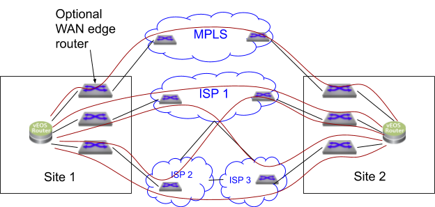
The previous example shows a network with five possible paths: one MPLS path and four paths via Internet Service Providers (ISPs) - ISP1, ISP1-ISP3, ISP2-ISP3, and ISP2-ISP1. Each ISP offers different costs, bandwidth, AWE-7200R and CloudEOS router characteristics, and SLAs. This multi-ISP model benefits users who seek cost-effective network solutions without compromising application performance.
Traditional enterprises often use MPLS VPNs, which offer excellent AWE-7200R and CloudEOS router characteristics, such as latency, but come at a high cost and with limited geographic availability. With its higher bandwidth and lower costs, the Internet has emerged as an alternative AWE-7200R and CloudEOS router option. However, inconsistent SLAs can be challenging to maintain application performance across multiple ISPs. Traditional routing solutions cannot optimize routing across diverse AWE-7200R and CloudEOS router SP networks.
Overview
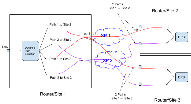
The following section provides a functional overview of the Dynamic Path Selection feature. The diagram illustrates a network topology consisting of three routers at different locations, interconnected through two service providers. Site 1 has a central hub in this configuration, and establishes connections with Site 2 and Site 3. Two distinct paths exist between Site 1 and Site 2, and two separate paths exist between Site 1 and Site 3.
Path Definition Overview
A path represents a pair of interfaces, a source interface, and a destination interface, with traffic flowing from site to site. For example, eth1/router1 -- eth1/router2 denote a path. Note that there could be many paths through the same egress interface. The path does not refer to the packet's network path through the SP network. There could be multiple network paths in the SP network from the customer edge router to another edge router. Also, the network paths can change. A path has unidirectional properties, and path characteristics track in each direction.
Dynamic Load Balancing
Dynamic load balancing selects the best path, destination IP and egress interface, to a destination for a given application. The algorithm selects the best paths based on user-specified priorities or constraints, and dynamic load balance flows across selected paths.
AWE-7200R and CloudEOS router Overlay using VXLAN

r1addr and r2addr addresses have accessibility through SP networks, the VXLAN overlay works similarly to the datacenter network. The internal VTEP IP address cannot be reached over the SP networks. While you can configure the VTEP IP address as routable over MPLS network, unlike ISP, and since you want to load balance across SP networks dynamically,the router does not advertise the VTEP IP address over MPLS. However, the AWE-7200R and CloudEOS router interfaces have SP routable IP addresses. For example, the AWE-7200R and CloudEOS router1 has a routable IP address, r1w1, and the AWE-7200R and CloudEOS router2 has a routable IP address, r1w2. The forwarding engine replaces the VTEP address on the packet based on the selected path before sending it to the SP network.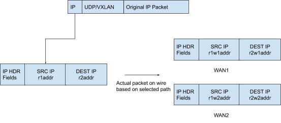
- The router VTEP IP V1 contains the nexthop for all the customer prefixes, and the customer prefixes
p1, and others advertise using the EVPN type 5 address family. - Access VTEP IP V1 through the two publicly routable AWE-7200R and CloudEOS router IP addresses, the
r1w1andr1w2addresses.
The router must know the SP routable IP addresses to reach each.
interface dps 1
The interface dps 1, created by default, represents the dps interface. Similar to the VXLAN interface, it carries all inter-site AWE-7200R and CloudEOS router traffic. The system applies any policies to the packet before encapsulation to this interface.
Peer VTEP Reachability
- MPLS - ip11, ip21
- Internet ip12 - ip22
- Internet ip12 - ip23
- Internet ip13 - ip22
- Internet ip13 - ip23
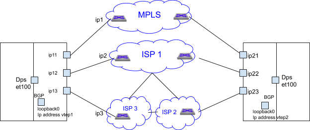
Peer VTEP reachability must be configured statically, but exchanged through BGP in the future. BGP runs on the same loopback interface used as the VXLAN source VREP interface in underlay.
The router tracks the available configured paths using routing updates, interface state, and programs the available paths for forwarding.
Control Plane Traffic
All BGP traffic between sites traverse the dps interface, utilizing path selection to ensure leveraging of all path selection features. Diverse path selection policies can be established to manage both control plane traffic types and end applications.
Load Balancing Algorithm
The Load Balancing algorithm selects the path that fulfills all the criteria for an application. If multiple paths meet the criteria, the load balances across those paths. If none of the paths meet all the criteria, it selects the path with the lowest loss rate.
The selected path for a given flow stores in the flow cache, and not reevaluated for constraints. Even if the path characteristics no longer meet the user-specified criteria, packets from that flow continue to take the same path.
- The path becomes inactive.
- The flow remaps to a different application.
- When the user changes the constraints or priority, the path no longer has validity for this flow.
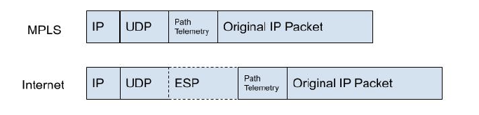
Path Telemetry
The Path Telemetry feature provides the ability to determine the AWE-7200R and CloudEOS router path state and measure the characteristics, including latency (one-way delay), jitter, packet loss rate, and throughput.
Path State Determination
Path telemetry uses keepalive and feedback packets to determine the path state. It sends out periodic keepalive packets, and after a second, when it receives a peer’s feedback packet, the path becomes active, and measures its characteristics. Accordingly, if no feedback packet received within a certain period, such as after 5 keepalive packets, the path becomes inactive and used for path selection.
configuration
This section discusses the commands to configure and verify the Dynamic Path Selection feature.
Defining Paths
A path represents a pair of interfaces or their IP addresses, a source interface, and a destination interface for traffic can flow from site to site.
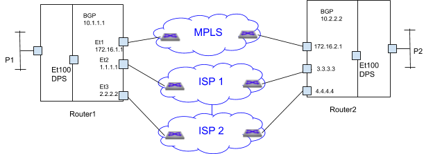
- MPLS path - 172.16.1.1 -- 172.16.2.1
- 4 Internet paths
- 1.1.1.1 -- 3.3.3.3
- 1.1.1.1 -- 4.4.4.4
- 2.2.2.2 -- 3.3.3.3
- 2.2.2.2 -- 4.4.4.4
However, some paths cross ISPs, for example, 1.1.1.1 -- 4.4.4.4 goes from router1 through ISP 1, ISP 2 to router2. In some customer scenarios, ISP2 can be an LTE SP and used as a backup in case ISP 1 fails. In this case, the paths 1.1.1.1 -- 4.4.4.4 and 2.2.2.2 -- 3.3.3.3 should not be used.
- Restrict paths - define which paths are valid among the available paths, like the LTE backup SP discussed before.
- Apply specific policies to the path group. Apply encryption for all Internet paths.
Configure path-group commands in the router Path Selection configuration Mode,router path-selection.
router path-selection
path-group <group-name>
local interface <intf-name>
## more local interface commands
## that belong to the same path-group, eg Internet
peer static router-ip <ip-address>
ipv4 address <ip-addr1>
## more IP addresses through which the router can be reached
The router-IP is the same as the VTEP-IP. local used to configure the local AWE-7200R and CloudEOS router IP address or interface part of the path-group. Use Peers to configure the remote VTEP reachability statically.
Each combination of peer and local IP addresses provides a potential path. If routing resolves the remote IP through a local interface, then that local-remote IP pair becomes a real path used for forwarding.
- mpls-group
- Internet-group
Further, if paths must be restricted through the Internet, divide the Internet groups into more groups. For example, the customer can define ISP1 and ISP2-ISP3 as separate groups and create 2 Internet paths instead of 4.
Creating Path-Groups under Path-Selection
Syntax
router path-selection path-groupname
name - Specify the name of the path group.
Example
router(config)#router path-selection
router(config-dynamic-path-selection)#
router(config-dynamic-path-selection)#path-group mpls
Specifying Local interfaces under Path-Group Sub-Mode
Syntax
path-group <name> local interface <intf-name>
Configure the local interface on the local AWE-7200R and CloudEOS router interface part of the path-group. The AWE-7200R and CloudEOS router interface uses the assigned IP addresses as AWE-7200R and CloudEOS router IP addresses. Multiple interfaces can be specified.
Example
In the above deployment, ether1 is part of MPLS path-group.
router(config-dynamic-path-selection)# path-group mpls
router(config-path-group-mpls)# local interface ether1

Ethernet 2 and 3 are part of Internet path-group
router(config-dynamic-path-selection)# path-group internet
router(config-path-group-internet)# local interface ether2
router(config-path-group-internet)# local interface ether3
Specifying Remote VTEPs and Reachability Statically
Syntax
path-group <name> peer static router-ip <ip-address> ipv4 address <ip-addr1> ipv4 address <ip-addr2>
The parameter, peer static, configures the remote VTEP reachability statically through routable IP addresses over the SP network. The router-IP uses the VTEP IP address. In the Internet, the routable IP address uses a public IP address. In the case of MPLS, the MPLS provider can reach using an enterprise specific private IP address. Typically, configure customer edge routers (CEs) to exchange subnets by running eBGP on the SP PE router.
Example
router(config-dynamic-path-selection)# path-group mpls
router(config-path-group-mpls)# peer static router-ip 10.2.2.2
router(config-peer-router-ip-10.2.2.2-mpls)# ipv4 address 172.16.2.1

For the Internet path group router2’s router IP 10.2.2.2 is reachable via two IP addresses only via ISP1 3.3.3.3 and another through ISP2 4.4.4.4

router(config-dynamic-path-selection)# path-group internet
router(config-path-group-internet)# peer static router-ip 10.2.2.2
router(config-peer-router-ip-10.2.2.2-internet)# ipv4 address 3.3.3.3
router(config-peer-router-ip-10.2.2.2-internet)# ipv4 address 4.4.4.4
Example
router(config)# router path-selection
router(config-dynamic-path-selection)# path-group mpls
router(config-path-group-mpls)# local interface et1
router(config-path-group-mpls)# peer static router-ip 10.2.2.2
router(config-peer-router-ip-10.2.2.2-mpls)# ipv4 address 172.16.2.1
router(config-peer-router-ip-10.2.2.2-mpls)# path-group internet
router(config-path-group-internet)# local interface et2
router(config-path-group-internet)# local interface et3
router(config-path-group-internet)# peer static router-ip 10.2.2.2
router(config-peer-router-ip-10.2.2.2-internet)# ipv4 address 3.3.3.3
router(config-peer-router-ip-10.2.2.2-internet)# ipv4 address 4.4.4.4

The paths defined are
MPLS path - 172.16.1.1 -- 172.16.2.1
4 Internet paths
1.1.1.1 -- 3.3.3.3
1.1.1.1 -- 4.4.4.4
2.2.2.2 -- 3.3.3.3
2.2.2.2 -- 4.4.4.4

However if ISP2 is a LTE and the customer does not want paths to cross over from ISP1 to LTE then the configuration should be

router(config)# router path-selection
router(config-dynamic-path-selection)# path-group mpls
router(config-path-group-mpls)# local interface et1
router(config-path-group-mpls)# peer static router-ip 10.2.2.2
router(config-peer-router-ip-10.2.2.2-mpls)# ipv4 address 172.16.2.1
router(config-peer-router-ip-10.2.2.2-mpls)# path-group internet
router(config-path-group-internet)# local interface et2
router(config-path-group-internet)# peer static router-ip 10.2.2.2
router(config-peer-router-ip-10.2.2.2-internet)# ipv4 address 3.3.3.3
router(config-peer-router-ip-10.2.2.2-internet)# path-group lte
router(config-path-group-lte)# local interface et3
router(config-path-group-lte)# peer static router-ip 10.2.2.2
router(config-peer-router-ip-10.2.2.2-lte)# ipv4 address 4.4.4.4

In the above case the paths are
MPLS path - 172.16.1.1 -- 172.16.2.1
Internet path 1.1.1.1 -- 3.3.3.3
LTE path 2.2.2.2 -- 4.4.4.4.
Underlay dps configuration
To enable the exchange of dps paths and EVPN routes, configure the VXLAN with the private IP address of a loopback interface. The dps interface configuration should be divided and applied under two L3 interfaces, VXLAN1 and et100.
dps interface configuration
Add any private IP address to configure the dps interface as a Layer 3 interface. However, the interface does not use the assigned IP address for routing.
Syntax
interface dps1
router(config)# interface dps1
router(config-if-Dp1)# no routerport
router(config-if-Dp1)# ip address 11.0.0.1/24
VXLAN configuration
In the example, the configuration uses a private IP, 1.1.1.1 configured in loopback 0 interface and used as a VXLAN source interface.
Example
router(config)# interface loopback 0
router(config-if-Lo0)# ip address 1.1.1.1/32
router(config-if-Lo0)# interface vxlan1
router(config-if-Vx1)# vxlan source-interface dps1
router(config-if-Vx1)# vxlan udp-port 4789
router(config-if-Vx1)# vxlan vrf vrf1 vni 100
BGP uses on the same loopback IP as the VXLAN source interface IP. In the above example, BGP uses the IP addresses, 1.1.1.1, 2.2.2.2, and 3.3.3.3 for each peer.
Applying Policies for Path Groups
The policies for the path groups applies to all the paths in the group. CloudEOS supports the following policy:
Encrypting Path-Group
Applying an IPsec profile to the group encrypts all paths within the group according to the profile. This policy, used to encrypt all Internet paths, simplifies IPsec configuration by eliminating the need to specify the traffic for encryption.
Syntax
path-group name ipsec profile ipsec-profile-name
Applying an IPsec profile encypts all the paths in the path group based on the algorithms and authentication mechanisms per the profile.
Configuring Load Balancing Profile
Configure the load balancing policy using the command router path-selection.
Syntax
router path-selection load-balance policy name latency milliseconds jitter ;milliseconds loss-rate 0.00-100.00 percentage path-group group-name [ priority number] path-group group-name
Specifying Path Groups to the Load Balancer
Syntax
router path-selection load-balance policy <name> path-group <group-name> path-group <group-name>
When specifying multiple path-groups, flows load-balance across all the paths in the specified path-groups.
Example
router(config)# router path-selection
router(config-dynamic-path-selection)# load-balance policy best-effort
router(config-load-balance-policy-best-effort)# path-group mpls
router(config-load-balance-policy-best-effort)# path-group internet
Specifying Constraints for Path Selection
Syntax
router path-selection load-balance policy <name> latency <milliseconds> jitter <milliseconds> loss-rate <0.00-100.00 percentage>
Path selection can be based on specified latency, jitter, and loss-rate constraints. Flows load-balance across all selected paths when multiple paths meet the constraints. If no paths meet all the requirements, select the path with the lowest loss rate.
Example
router(config-path-selection)# load-balance policy voice
router(config-load-balance-policy-voice)# path-group mpls
router(config-load-balance-policy-voice)# path-group internet
router(config-load-balance-policy-voice)# latency 50
router(config-load-balance-policy-voice)# loss-rate 1
In this case, the traffic load-balances across all the paths that meet the constraints. If none matches, then the router sends the traffic to the best path.
Specifying Preference to a Path-Group
Syntax
router path-selection load-balance policy name path-group group-name [ priority number] path-group group-name
Path group preference can be specified for load balancing flows. A lower priority number indicates higher priority for the path group. If unspecified, the router uses the default priority of 1 (highest). Traffic load balances among path groups within the same load-balance profile that share the same priority. If no available paths in a path group, the router considers paths from the next lower priority group. Reasons for path unavailability may include the following:
- The interface has the status,
down. - The route has not resolved.
- Path keepalives have failed.
- The load balancing policy specified constraints have not been met.
Example
router(config-dynamic-path-selection)# load-balance policy voice
router(config-load-balance-policy-voice)# path-group mpls
router(config-load-balance-policy-voice)# path-group internet
When the MPLS path goes down, all the existing flows forward through Internet paths. When the MPLS path returns to active, all the new flows forward through MPLS paths.
Classification - Application Profiles
Use the following commands in CloudEOS.
Syntax
application traffic recognition application ipv4 http-8080 { protocol <proto> [ destination-port { <port_num> | <port-range> } ] } protocol tcp destination-port 8080 protocol tcp destination-port 8000 application ipv4 app2-service protocol tcp destination-port 8001-8080
The application configuration, which can be specified with custom signatures or imported from a DPI engine, should be extended to include path-selection.
Syntax
Applications can be grouped, and attributes such as the traffic class can be specified using the application profile below.
application traffic recognition application-profile app-xyz application <app-name-1> application <app-name-2>
Example
router(config)# application traffic recognition
router(config-app-recognition)# application-profile gold
router(config-app-profile-gold)# application voice
router(config-app-profile-gold)# traffic-policies

“bronze” profile for best effort
router(config-app-recognition)# application-profile bronze
router(config-app-profile-bronze)# application best-effort
router(config-app-profile-bronze)# traffic-policies
Path Selection Policy
The load balancing policy can be specified based on the application.
Syntax
router path-selection policy <dps-policy-name> <rule key> application-profile <profile-name> load-balance <load balance policy name> <rule key> application-profile <profile-name> load-balance <load balance policy name>
The configuration requires sequence numbers since a flow can match multiple application profiles. Also, set load-balance as a sub-mode to add other actions for “match application-profile.”
router(config)# router path-selection
router(config-dynamic-path-selection)# policy dynamic
router(config-policy-dynamic)# 10 application-profile voice
router(config-policy-rule-key-10-dynamic)# load-balance voice
router(config-policy-rule-key-10-dynamic)# 20 application-profile best
router(config-policy-rule-key-20-dynamic)# load-balance best
Applying the Path Selection Policy
Use VXLAN encapsulated VTI interfaces for all site-to-site traffic. Each VRF has distinct classification and path selection policies. For example, the test VRF could have a straightforward application classification and load-balancing policy.
Syntax
router path-selection vrf vrf-name path-selection-policy policy-name
VRF all applies a policy on all VRFs. If both all and per VRF policy specified, only the per VRF policy applies.
To prevent unnecessary classification overhead for LAN-to-LAN traffic, the policy, classification and load balancing, only applies to the datapath after identifying traffic as site-to-site.
When applied to a VRF, the policy implementes in the egress direction on the hidden SVI interface for the VTI VXLAN tunnel interface. The policy is disregarded if no VTI is configured.

router(config)# router path-selection
router(config-dynamic-path-selection)# vrf red
router(config-vrf-red)# path-selection-policy production
router(config-vrf-red)#
Path Telemetry UDP Port
By default, the path telemetry protocol uses 4793 as the destination UDP port number for encapsulation. Use the following command to configure the UDP port for dps.
Syntax
router path-selection encapsulation path-telemetry udp port number
router(config)# router path-selection
router(config-dynamic-path-selection)# encapsulation path-telemetry udp port 4794
Complete Path Selection configuration Example

router# application traffic recognition
router(config-app-recognition)# application-profile platinum
router(config-app-profile-platinum)# application voice
router(config-app-profile-platinum)# application skype-voice
router(config-app-profile-platinum)# application-profile bronze
router(config-app-profile-bronze)# application scp
router(config-app-profile-bronze)# application ftp
router(config-app-profile-bronze)# router path-selection
router(config-dynamic-path-selection)# path-group mpls
router(config-path-group-mpls)# local interface et1
router(config-path-group-mpls)# peer static router-ip 10.2.2.2
router(config-peer-router-ip-10.2.2.2-mpls)# ipv4 address 172.16.2.1
router(config-peer-router-ip-10.2.2.2-mpls)# path-group internet
router(config-path-group-internet)# local interface et2
router(config-path-group-internet)# local interface et3
router(config-path-group-internet)# peer static router-ip 10.2.2.2
router(config-peer-router-ip-10.2.2.2-internet)# ipv4 address 3.3.3.3
router(config-peer-router-ip-10.2.2.2-internet)# ipv4 address 4.4.4.4
router(config-dynamic-path-selection)# load-balance policy voice
router(config-load-balance-policy-voice)# latency 50
router(config-load-balance-policy-voice)# path-group mpls
router(config-load-balance-policy-voice)# path-group internet priority 2
router(config-load-balance-policy-voice)# load-balance policy best-effort
router(config-load-balance-policy-best-effort)# path-group mpls
router(config-load-balance-policy-best-effort)# path-group internet
router(config-load-balance-policy-best-effort)# load-balance policy default
router(config-load-balance-policy-default)# path-group internet
router(config-load-balance-policy-default)# policy dynamic
router(config-policy-dynamic)# 10 application-profile platinum
router(config-policy-rule-key-10-dynamic)# load-balance voice
router(config-policy-rule-key-10-dynamic)# 20 application-profile bronze
router(config-policy-rule-key-20-dynamic)# load-balance best-effort
router(config-dynamic-path-selection)# policy dynamic
router(config-policy-dynamic)# interface ethernet 100
router(config-if-Et100)# no routerport
router(config-if-Et100)# ip address 11.0.0.1/24
router(config-if-Et100)# interface loopback 0
router(config-if-Lo0)# ip address 10.1.1.1/32
router(config-if-Lo0)# interface vxlan 1
router(config-if-Vx1)# vxlan source-interface loopback 0
router(config-if-Vx1)# vxlan udp-port 4789
router(config-if-Vx1)# vxlan vrf vrf1 vni 100
router(config-if-Vx1)# ip route 10.2.2.2/32 ethernet 100
router(config)# arp 10.2.2.2 00:00:33:02:00:00 arpa
router(config)#
Site-1
router(config)# router path-selection
router(config-dynamic-path-selection)# path-group 1
router(config-path-group-1)# local interface ethernet 5
!
router(config-path-group-1)# peer static router-ip 22.22.22.22
router(config-peer-router-ip-22.22.22.22-1)# ipv4 address 8.0.1.5
!
router(config-peer-router-ip-22.22.22.22-1)# load-balance policy policy-1
router(config-load-balance-policy-policy-1)# path-group 1
!
router(config-load-balance-policy-policy-1)# policy policy-1
router(config-policy-policy-1)# default-match
router(config-policy-default-rule-policy-1)# load-balance policy-1
!
router(config-policy-default-rule-policy-1)# vrf default
router(config-vrf-default)# path-selection-policy policy-1
!
router(config-dynamic-path-selection)# vrf et1
router(config-vrf-et1)# path-selection-policy policy-1
!
router(config-vrf-et1)# vrf instance et1
router(config-vrf-et1)# interface ethernet 1
router(config-if-Et1)# description LAN-interface
router(config-if-Et1)# no routerport
router(config-if-Et1)# ip address 4.0.1.5/24
!
router(config)# vrf instance et1
router(config-vrf-et1)# interface ethernet 1
router(config-if-Et1)# description LAN-interface
router(config-if-Et1)# no routerport
router(config-if-Et1)# ip address 4.0.1.5/24
!
router(config-if-Et1)# interface ethernet 5
router(config-if-Et5)# description WAN-interface
router(config-if-Et5)# no routerport
router(config-if-Et5)# ip address 5.0.1.5/24
!
router(config-if-Et5)# interface ethernet 100
router(config-if-Et100)# no routerport
router(config-if-Et100)# ip address 10.0.0.2/24
!
router(config-if-Et100)# interface loopback 1
router(config-if-Lo1)# ip address 11.11.11.11/32
!
router(config-if-Lo1)# interface vxlan 1
router(config-if-Vx1)# vxlan source-interface loopback 1
router(config-if-Vx1)# vxlan udp-port 4789
router(config-if-Vx1)# vxlan vrf et1 vni 5
!
router(config-if-Vx1)# ip route 22.22.22.22/32 ethernet 100
!
router(config)# arp 22.22.22.22 22:22:22:22:22:22 arpa
!
router(config)# ip routing
router(config)# ip routing vrf et1
!
router(config)# router bgp 32
router(config-router-bgp)# neighbor 5.0.1.1 remote-as 501
router(config-router-bgp)# neighbor 5.0.1.1 maximum-routes 12000
router(config-router-bgp)# neighbor 22.22.22.22 remote-as 43
router(config-router-bgp)# neighbor 22.22.22.22 update-source loopback 1
router(config-router-bgp)# neighbor 22.22.22.22 ebgp-multihop
router(config-router-bgp)# neighbor 22.22.22.22 send-community extended
router(config-router-bgp)# neighbor 22.22.22.22 maximum-routes 12000
router(config-router-bgp)# redistribute static
!
router(config-router-bgp)# address-family evpn
router(config-router-bgp-af)# neighbor 22.22.22.22 activate
!
router(config-router-bgp-af)# exit
router(config-router-bgp)# address-family ipv4
router(config-router-bgp-af)# no neighbor 22.22.22.22 activate
router(config-router-bgp-af)# exit
!
router(config)# router bgp 32
router(config-router-bgp)# vrf et1
router(config-router-bgp-vrf-et1)# rd 4.0.1.5:0
router(config-router-bgp-vrf-et1)# route-target import evpn 9.0.1.5:0
router(config-router-bgp-vrf-et1)# route-target export evpn 4.0.1.5:0
router(config-router-bgp-vrf-et1)# router-id 4.0.1.5
router(config-router-bgp-vrf-et1)# network 4.0.1.0/24
router(config-router-bgp-vrf-et1)# network 50.0.0.0/24
router(config-router-bgp-vrf-et1)# exit

router(config-router-bgp) #exit
router(config)#
-------------------------------------------------------------------------
Site-2
router(config)# router path-selection
router(config-dynamic-path-selection)# path-group 1
router(config-path-group-1)# local interface ethernet 1
!
router(config-path-group-1)# peer static router-ip 11.11.11.11
router(config-peer-router-ip-11.11.11.11-1)# ipv4 address 5.0.1.5
!
router(config-peer-router-ip-11.11.11.11-1)# load-balance policy policy-1
router(config-load-balance-policy-policy-1)# path-group 1
!
router(config-load-balance-policy-policy-1)# policy policy-1
router(config-policy-policy-1)# default-match
router(config-policy-default-rule-policy-1)# load-balance policy-1
!
router(config-policy-default-rule-policy-1)# vrf default
router(config-vrf-default) #path-selection-policy policy-1
!
router(config-dynamic-path-selection)# vrf et5
router(config-vrf-et5)# path-selection-policy policy-1
!
router(config-vrf-et5)# vrf instance et5
router(config-vrf-et5)# interface ethernet 1
router(config-if-Et1)# description WAN-interface
router(config-if-Et1)# no routerport
router(config-if-Et1)# ip address 8.0.1.5/24
!
router(config)# vrf instance et5
router(config-vrf-et5)# interface ethernet 5
router(config-if-Et5)# description LAN-interface
router(config-if-Et5)# no routerport
router(config-if-Et5)# ip address 9.0.1.5/24
!
router(config-if-Et5)# interface ethernet 100
router(config-if-Et100)# no routerport
router(config-if-Et100)# ip address 10.0.0.1/24
!
router(config-if-Et100)# interface loopback 1
router(config-if-Lo1)# ip address 22.22.22.22/32
!
router(config-if-Lo1)# interface vxlan 1
router(config-if-Vx1)# vxlan source-interface loopback 1
router(config-if-Vx1)# vxlan udp-port 4789
router(config-if-Vx1)# vxlan vrf et5 vni 5
!
router(config-if-Vx1)# ip route 11.11.11.11/32 ethernet 100
!
router(config)# arp 11.11.11.11 11:11:11:11:11:11 arpa
!
router(config)# ip routing
router(config)# ip routing vrf et5
!
router(config)# router bgp 43
router(config-router-bgp)# maximum-paths 16
router(config-router-bgp)# neighbor 8.0.1.1 remote-as 701
router(config-router-bgp)# neighbor 8.0.1.1 maximum-routes 12000
router(config-router-bgp)# neighbor 11.11.11.11 remote-as 32
router(config-router-bgp)# neighbor 11.11.11.11 update-source loopback 1
router(config-router-bgp)# neighbor 11.11.11.11 ebgp-multihop
router(config-router-bgp)# neighbor 11.11.11.11 send-community extended
router(config-router-bgp)# neighbor 11.11.11.11 maximum-routes 12000
!
router(config-router-bgp)# address-family evpn
router(config-router-bgp-af)# neighbor 11.11.11.11 activate
router(config-router-bgp-af)# exit
!
router(config-router-bgp)# address-family ipv4
router(config-router-bgp-af)# no neighbor 11.11.11.11 activate
router(config-router-bgp-af)# exit
!
router(config)# router bgp 40
router(config-router-bgp)# vrf et5
router(config-router-bgp-vrf-et5)# rd 9.0.1.5:0
router(config-router-bgp-vrf-et5)# route-target import evpn 4.0.1.5:0
router(config-router-bgp-vrf-et5)# route-target export evpn 9.0.1.5:0
router(config-router-bgp-vrf-et5)# router-id 9.0.1.5
router(config-router-bgp-vrf-et5)# network 9.0.1.0/24
router(config-router-bgp-vrf-et5)# network 51.0.0.0/24
router(config-router-bgp-vrf-et5)# exit
router(config-router-bgp)# exit
router(config)#
dps Display Commands
Use he following show commands to verify the various information of the Dynamic Path Selection application.
Path Telemetry Show Commands
These two show commands provide path telemetry status:
show monitor telemetry path characteristics [ detail ][ destination DSTIP ][ path-name NAME ][ peer PEERIP ] [ source SRCIP ] [ traffic-class TC ]
show monitor telemetry path counters [ detail ][ destination DSTIP ][ path-name NAME ][ peer PEERIP ] [ source SRCIP ][ traffic-class TC ]
Example
- The show monitor telemetry path characteristics command displays the path state, latency, jitter, and other information.
router# show monitor telemetry path characteristics
PathName TrafficClassTxStateLatency(ms)Jitter(ms)Throughput(Mbps)LossRate(%)
path10 active 3.520 1.12210.000.01
path20 active 35.2202.33010.001.01

router# show monitor telemetry path characteristics detail
Peer: 10.1.10.5
PathName: path1
Source: 156.142.20.23, Destination: 156.142.40.21
Traffic Class: 0
TxState: active
Latency: 3.520 ms
Jitter:1.122 ms
Throughput: 10.00 Mbps
LossRate: 0.01 %
PathName: path2
Source: 156.142.20.24, Destination: 156.142.40.22
Traffic Class: 0
TxState: active
Latency: 35.220 ms
Jitter:2.330ms
Throughput: 1000 Mbps
LossRate: 1.01 %
- The show monitor telemetry path counters displays input-output bytes, packets, and flow information.
router# show monitor telemetry path counters
PathName TrafficClassInBytesInPktsInPktsDropOutBytesOutPktsOutPktsDrop
path10 455330010220 5341333 7520
path20 455330010220 5341333 7520

kvs17-b10# show monitor telemetry path counters detail
Peer: 10.1.10.5
PathName: path1
Source: 156.142.20.23, Destination: 156.142.40.21
Traffic Class: 0
InBytes: 4553300
InPkts: 1022
InPktsDrop: 0
OutBytes: 5341333
OutPkts: 752
OutPktsDrop: 0
Both path characteristics and path counters show results that can be filtered by path name, destination IP, source IP, remote IP, and traffic class. Both have detailed version output and brief version output but the default version is the brief version.
IPsec Show Commands
The following IPsec show commands filter IPsec connections based on path name and remote IP address. The IPsec show results are filtered using the following options: Tunnel, Detail, Path, and VRF.
- The show ip security connection path command displays all path-based IP security connections.
router# show ip security connection path

NameSource Dest Status Uptime InputOutput Rekey Time
Path1 ip1ip3Established22 minutes 0 bytes0 bytes34 minutes
		0 pkts 0 pkts
Path2 ip2ip3Established22 minutes 0 bytes0 bytes34 minutes
		0 pkts 0 pkts
Path2 ip5ip6Established22 minutes 0 bytes0 bytes34 minutes
 		 0 pkts 0 pkts
- The show ip security connection path name command displays IPsec path connections based on the path name.
router# show ip security connection path name path1

NameSource Dest Status Uptime InputOutput Rekey Time
Path1 ip1ip3Established22 minutes 0 bytes0 bytes34 minutes
		 0 pkts 0 pkts
- The show ip security connection path peer command displays the IPsec path connections based on the remote router IP.
router# show ip security connection path peer ip3

NameSource Dest Status Uptime InputOutput Rekey Time
Path1 ip1ip3Established22 minutes 0 bytes0 bytes34 minutes
		0 pkts0 pkts
Path2 ip2ip3Established22 minutes 0 bytes0 bytes34 minutes
		0 pkts0 pkts
Load-Balance and Application Counters
These counters display the statistics of load-balancing based on an application profile, overlay VRF, and remote node IP:
show path-selection load-balance counter [ detail ] [ application-profile APPNAME ] [ peer PEERIP ] [ vrf VRFNAME ]
show path-selection application counters[ application-profile APPNAME ] [ peer PEERIP ] [ vrf VRFNAME ]
- The show path-selection load-balance counter command displays every application profile, overlay VRF, and remote IP, per path group flow count, and the throughput of the path group.
router#show path-selection load-balance counters

AppProfileVrfPeer PathGroupPath Flows Throughput(Mbps)
app1vrf1 11.0.1.1 transit0 path20 0.00
app2vrf1 11.0.1.1 transit1 path10 0.00
default_app default11.0.1.1 transit0 path20 0.00
transit1 path10 0.00
- The show path-selection load-balance counters detail command displays for every application profile, overlay VRF, and remote IP per path group flow count, out bytes, out packets, and the throughput of path group.
router#show path-selection load-balance counters detail

AppProfileVrf Peer PathGroup PathFlows Throughput(Mbps)OutBytes OutPkts
app1vrf111.0.1.1 transit0path2 0 0.0000
app2vrf111.0.1.1 transit1path1 0 0.0000
default_app default 11.0.1.1 transit0path2 0 0.001052 17
 transit1path1 0 0.001321 17
- The show path-selection application counters command displays the application profile, overlay VRF, and remote IP out bytes, out packets,and throughput.
router#show path-selection application counters

 AppProfile VRF PeerThroughput OutBytes OutPackets
SilverRed 10.0.0.1153000 15
The output of the show path-selection load-balance counters and the show path-selection application counters commands can be filtered by application profile name, peer IP address, and VRF name.
Clear Commands
The following commands clears the dps related counters:
Syntax
Clear load balancing and application counters:
clear path-selection counters
Clear path telemetry counters:
clear monitor telemetry path counters
Troubleshooting
- Verify the paths have an
EstaborEstab IPSecstate using the show path-selection paths command.- ARP Pending - Make sure the next-hop to the path destination IP is available.
- Route Pending - Make sure a route to the path destination IP is available through the local interface for the path.
- IPSec Pending - Check the IPSec connection with the show ip security connection command or other IPSec-related commands between the path’s local interface and the path’s destination.
- If the paths have an Estab state, verify active paths using the show monitor telemetry path characteristics command.
- If a path is inactive, ensure IP connectivity works between the path’s source IP/interface and destination IP. Ping the path destination with the path source IP could be one of the ways to verify this. Also, check the configuration and ensure both sites' paths are configured symmetrically.
- Check and make sure there are dps communications between the source and destination IPs using TCP dump on et100.
- Paths are active, but ping between loopbacks of the two sites is not working. Loopbacks should be reachable through the overlay.
- Check your interface VXLAN1 configuration.
- Check and make sure you have applied a policy with a default match to your vrf default configuration in dps.
- Site-to-site loopback IPs are reachable, but data traffic needs to go through.
- Check your EVPN configuration. Make sure the remote routes are in your VRF route table of your sites.
- Make sure your dps configuration has a proper policy, application profile, default match, and load-balance profile.
Limitations
- VNI Support - dps currently only supports VNI numbers within the range of 1 to 255.
- interface Uniqueness - The same interface cannot be configured locally across different dps path groups.
- VRF Requirement - dps AWE-7200R and CloudEOS router interfaces and local interfaces configured in path groups must reside within the default VRF.
- Port Translation - dps does not currently support port translation.