Rear Panel
All switches covered by this guide use one of the rear panels shown below. Some of the PSUs have a velcro strap for cable management.
Note: All devices are designed to fit into a 19” rack. The appearance may be different than those shown based on PSU and fan modules used.
Note: Handle or bezel color indicates airflow direction.
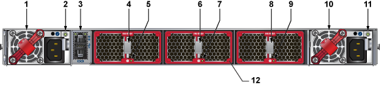
| 1 | Power supply module 1 | 5 | Fan module 1 status LED | 9 | Fan module 3 status LED |
| 2 | Power supply module 1 status LED | 6 | Fan module 2 release | 10 | Power supply module 2 |
| 3 | Management ports | 7 | Fan module 2 status LED | 11 | Power supply module 2 status LED |
| 4 | Fan module 1 release | 8 | Fan module 3 release | 12 | Fan module bezel1 |
.png)
| 1 | Fan module 1 | 4 | Fan module 4 | 7 | Earth grounding pad |
| 2 | Fan module 2 | 5 | Power supply module 1 | ||
| 3 | Fan module 3 | 6 | Power supply module 2 |