Installing the Access Point
This chapter contains the procedure to install the access point (AP).
Zero-Configuration of the Access Point
The AP supports zero-configuration under the following conditions:
- The device must be in AP mode with background scanning on and without a configured SSID.
- Set up a DNS entry for wifi-security-server on all the DNS servers. This entry should point to the IP address of the server. By default, the AP looks for the DNS entry wifi-security-server.
- Place the AP on a subnet with DHCP-enabled.
Assign a static IP to the AP or change the settings to DHCP. Make a note of the MAC address and the IP address of the AP in a safe place before installing it in a hard-to-reach location. Locate the MAC address of the AP on a label at the bottom of the product.
Ceiling Mounting the Access Point
Mounting the access point (AP) on the ceiling consists of the following steps:
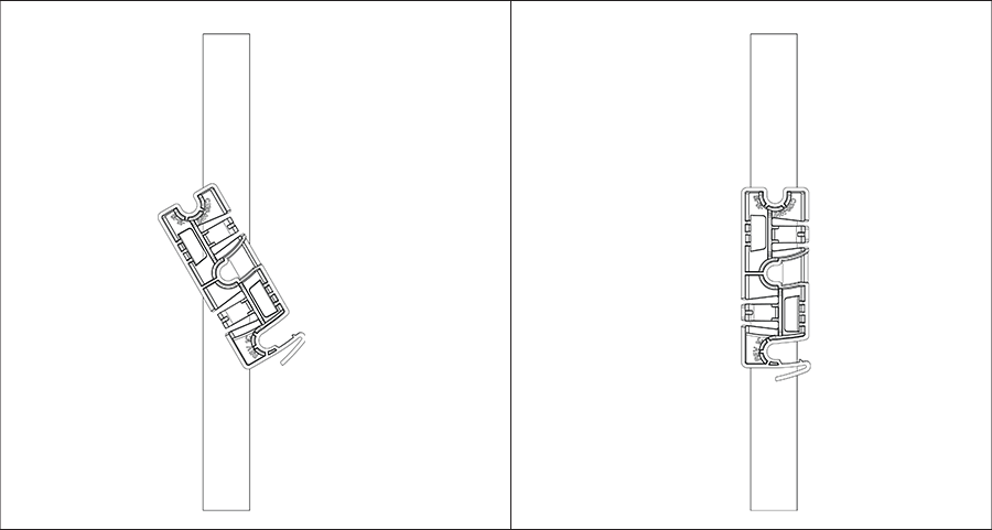
- Attach the bracket to the T-grid: Use the mounting bracket to install the AP on the ceiling. Attach the bracket to the T-grid and rotate the bracket so that it snaps on the T-grid. The bracket becomes parallel to an arm of the T-grid. Be sure the bracket properly snaps to the T-grid, as shown below.
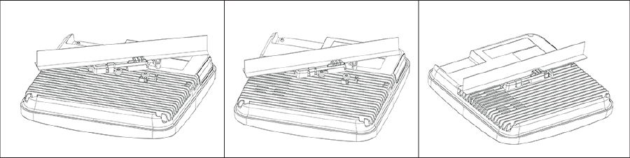
- Mounting the AP on the bracket: Place the first mounting post on the rear-side of the AP on to the lower notch of the bracket. Rotate the AP so the center mounting post fits in to the center notch on the bracket. Be sure all the mounting posts on the rear-side of the AP snap into the respective notches on the bracket. The mounting posts now properly fit in the respective notches of the bracket and the AP mounts properly.
 Mounting Instructions using the Silhouette/Interlude Bracket Mount: The standard package does not include the Silhouette/Interlude mounting bracket and must be procured separately. The mounting instructions for the Silhouette/Interlude Bracket Mount contain steps similar to the Standard Package Content mounting instructions.Note: As a best practice, label the APs using MAC addresses or your own convention. For example, use AP serial numbers so that you can easily identify the APs.
Wall Mounting the Access Point
For instructions on wall mounting the access point, refer to Wall Mount the Access Point article.
Connecting External Antennas to Access Point
Connect the external antennas to antenna ports available on the left and right of the AP. Use RP-SMA type connectors for the antennas. All the ports support multi-band connectivity - 2.4, 5, and 6 GHz.
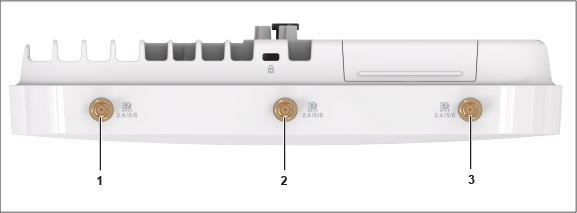
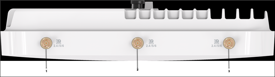
| 1 | Multi-band antenna for 2.4, 5, and 6 GHz bands. | 2 | Multi-band antenna for 2.4, 5, and 6 GHz bands. | 3 | Multi-band antenna for 2.4, 5, and 6 GHz bands. |