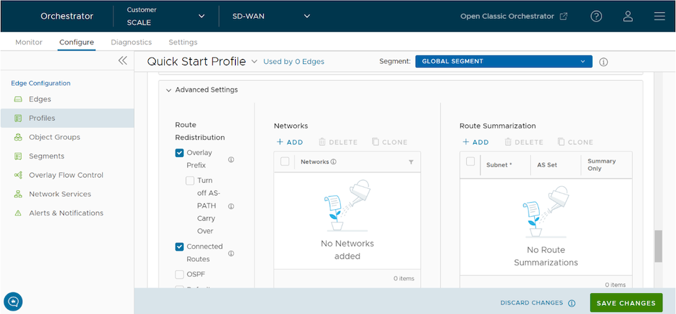
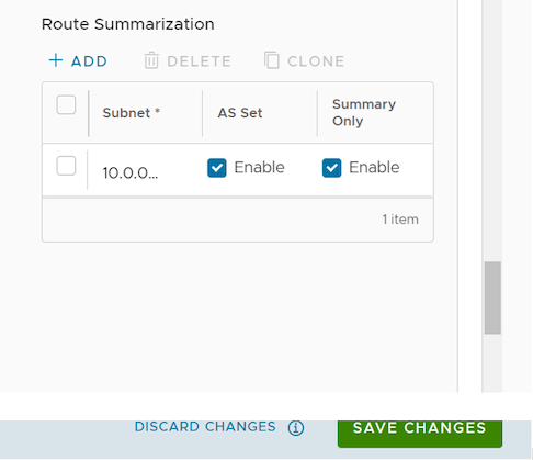
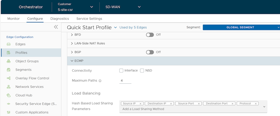
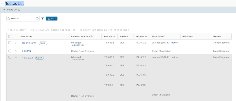
Note: If users login with a user ID with Customer Support privileges, users can only view Orchestrator objects. Users cannot create new objects or configure/update existing ones.
In the SD-WAN service of the Enterprise portal, users can perform configuration settings for a Profile by navigating to the Configure > Profiles > Device. For additional information about Segmentation, see Configure Segments with new Orchestrator UI.
Configure a Profile Device
The Device configuration page allows users to assign segments to a Profile and configure the settings and interfaces to associate with a Profile.
In the SD-WAN service of the Enterprise portal, when users select Configure > Profiles and select a Profile, the configuration options for the selected Profile display on the Device tab.
Figure 1. Profile Device tab
The View menu allows users to select the view options. The available options are Expand All and Collapse All.
The Sort menu allows users to select the sort options: Sort by category and Sort by segment aware. Users can view the configuration settings sorted by category or segment-aware. By default, the settings sort by category. If users choose Sort by segment aware, the settings group as Segment Aware and Segment Agnostic.
In Segment Agnostic configurations, configuration settings apply only to a specific segment selected from the Segment menu. In Segment Aware configurations, configuration settings apply to multiple segments.
Figure 2. Segment Aware and Segment Agnostic
Note: On the Device page, when users make configuration changes for the selected Profile, an action bar appears. Users can select the notification to view the recent configuration changes and save the changes made to the Profile.
Profile Device Configurations - A Roadmap
The following table provides the list of Profile-level configurations:
Table 1. Connectivity
Settings
Description
VLAN
Configure VLANs with both IPv4 and IPv6 addresses for Profiles. Select the IPv4 or IPv6 tabs to configure the corresponding IP addresses for the VLANs. See Configure VLAN for Profiles.
Management IP
Use the Management IP address as the source address for local services such as DNS, and as a destination for diagnostic tests such as pinging from another Edge. See Configure Management IP Address for Profiles.
To address high data usage on wireless links (LTE, 5G,USB Dongle), Orchestrator allows Enterprise users to configure the Wireless Link Management settings both at the Profile and Edge levels. See Configure Wireless Link Management for Profiles.
Global IPv6
Activate IPv6 configurations globally. See IPv6 Settings
Common Criteria (CC) is an international certification accepted by many countries. Obtaining the CC certification is an endorsement that our product has been evaluated by competent and independent licensed laboratories for the fulfilment of certain security properties. This certification is recognized by all the signatories of the Common Criteria Recognition Agreement (CCRA). The CC is the driving force for the widest available mutual recognition of secure IT products. Having this certification is an assurance of security to a standard extent and can provide Arista VeloCloud SD-WAN with the much needed business parity or advantage with its competitors. Enterprise users can configure the Common Criteria Firewall settings. By default, this feature is deactivated. See Configure Common Criteria Firewall Settings for Profiles.
Table 2. VPN Services
Settings
Description
Cloud VPN
Enable Cloud VPN to initiate and respond to VPN connection requests. Establish tunnels in the Cloud VPN as follows:
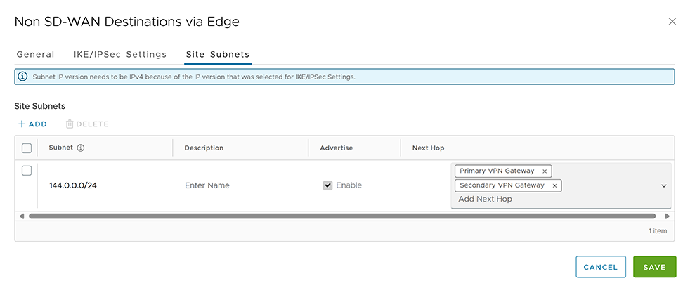
Enable to establish tunnel between a branch and Non SD-WAN destination via Edge. See Configure Tunnel Between Branch and Non SD-WAN Destinations via Edge. Select Add to add Non SD-WAN Destinations. Select New NSD via Edge to create new Non SD-WAN Destination via Edge. See Configure a Non SD-WAN Destinations via Edge.
Cloud Security Service
Enable to establish a secured tunnel from an Edge to cloud security service sites. This enables the secured traffic being redirected to third-party cloud security sites. See Configure Cloud Security Services for Profiles.
Use the DNS Settings to configure conditional DNS forwarding through a private DNS service and to specify a public DNS service used for querying purpose. See Configure DNS for Profiles.
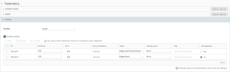
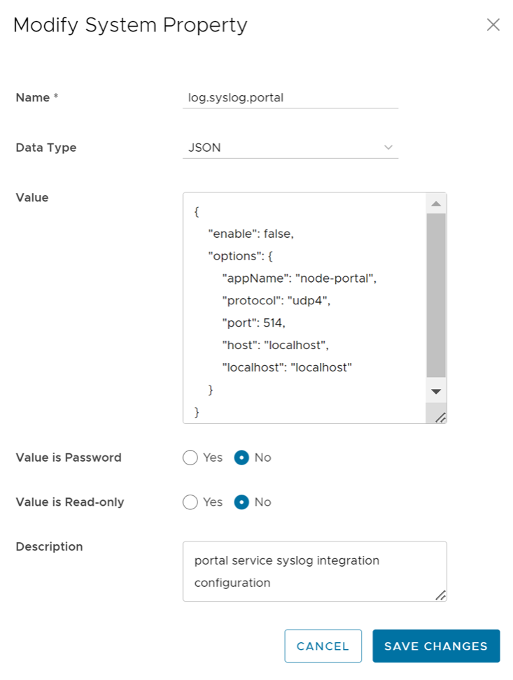
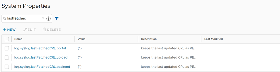
Configure the Syslog collector to receive Orchestrator events and firewall logs from the Edges configured in an Enterprise. See Configure Syslog Settings for Profiles.
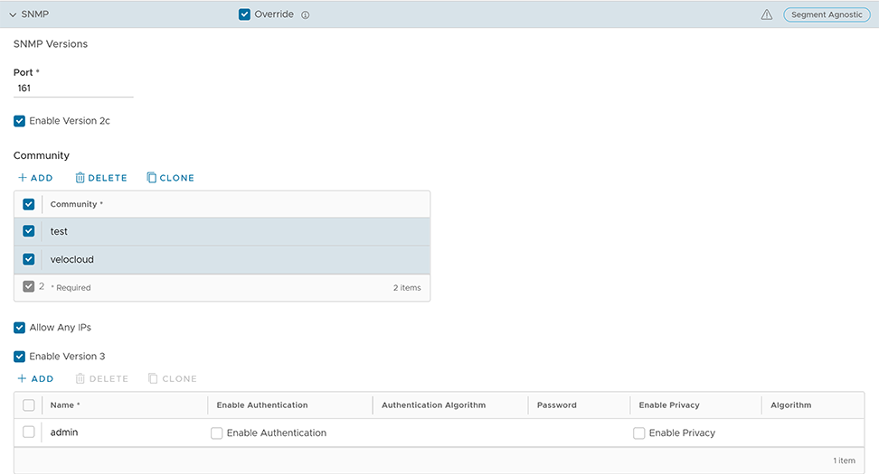
Activate the required SNMP version for monitoring the network. Ensure that users download and install all the required SNMP MIBs before enabling SNMP. See Configure SNMP Settings for Profiles.
After creating a Profile, users can select the Segments to include in their profile from the Segment menu on the Device tab.
To assign segments to a Profile, perform the following steps:
In the SD-WAN service of the Enterprise portal, go to Configure > Profiles to display a list of the existing Profiles.
Select on a Profile or select View in the Device column of the Profile to assign segments. Users can also select a Profile, then select Modify to configure the Profile. The configuration options for the selected Profile display on the Device tab.
From the Segment menu, select Change Profile Segments to display Change Profile Segments.
Figure 3. Change Profile Segments
Select the Segments to include in the profile. Segments with a lock symbol next to them indicate a Segment in use within a profile, and cannot be removed. Segments available for use display under All Segments.
Select Update Segments, then select Save Changes.
After users have assigned a Segment to the Profile, users can configure Segment through the Segment menu. All Segments available for configuration appear in the Segment menu. If a Segment assigned to a VLAN or interface, it displays the VLAN ID and the Edge models associated with it.
When users choose a Segment to configure from the Segment menu, depending upon the Segment options, the settings associated with that Segment appear in the Segments area.
Figure 4. Segment Settings
Configure VLAN for Profiles
As an Enterprise Administrator, configure VLANs in a Profile.
To configure VLAN settings in a Profile, use the following steps:
In the SD-WAN service of the Enterprise portal, go to Configure > Profiles.
Select on a Profile or select View in the Device column of the Profile. Users can also select a Profile and select Modify to configure the Profile.
The configuration options for the selected Profile display on the Device tab.
Scroll down to the Connectivity category and select VLAN.
Figure 5. VLAN
Add a new VLAN by selecting + Add VLAN. Delete a selected VLAN by selecting Delete. A VLAN already assigned to a device interface cannot be deleted.
Select IPv4 or IPv6 to display the respective list of VLANs.
Selecting + Add VLAN displays the following screen:
Figure 6. Add VLAN
In the Add VLAN window, configure the following VLAN details:
Table 6. Add VLAN - Options and Descriptions
Option
Description
General Settings
Segment
Select a segment from the list. The VLAN belongs to the selected segment.
VLAN Name
Enter a unique name for the VLAN.
VLAN ID
Enter the VLAN ID.
Description
Enter a description. (Optional)
LAN Interfaces
Users can configure the LAN Interfaces only at the Edge level.
SSID
Users can configure the Wi-Fi SSID details for the VLAN only at the Edge level.
ICMP Echo Response
Select to allow the VLAN to respond to ICMP echo messages.
DNS Proxy
Selected by default. This option allows users to activate or deactivate a DNS Proxy regardless of the IPv4 or IPv6 DHCP Server settings.
IPv4 and IPv6 Settings
Note:Users can activate either IPv4 or IPv6 or both settings.
Assign Overlapping Subnets
Select if users want to assign the same subnet for the VLAN to every Edge in the Profile and define the subnet in the Edge LAN IP Address. If users want to assign different subnets to every Edge, do not select the checkbox and configure the subnets on each Edge individually. Overlapping subnets for the VLAN are supported only for SD-WAN to SD-WAN traffic, providing that the LAN has NAT activated and SD-WAN to Internet traffic.
Edge LAN IPv4/IPv6 Address
Available only when users have selected Assign Overlapping Subnets as Yes. Enter the LAN IPv4/IPv6 address of the Edge.
CIDR Prefix / Prefix Length
Available only when users have selected Assign Overlapping Subnets as Yes. Enter the CIDR prefix for the LAN IPv4/IPv6 address.
Network
Enter the IPv4/IPv6 address of the Network.
OSPF
Available only when users have configured OSPF at the Profile level for the selected Segment. Select the checkbox and choose an OSPF area from the list. The OSPFv2 configuration supports only IPv4. The OSPFv3 configuration supports only IPv6. For additional information on OSPF settings and OSPFv3, see Activate OSPF for Profiles.
Multicast
Activates only when users have configured multicast settings for the Edge. Users can configure the following multicast settings for the VLAN.
IGMP
PIM
Select advanced multicast settings to set the following timers:
PIM Hello Timer
IGMP Host Query Interval
IGMP Max Query Response Value
VNF Insertion
Select to insert a VNF to the VLAN, which redirects traffic from the VLAN to the VNF. To activate VNF Insertion, ensure that the selected segment has a service VLAN mapped. For additional information about VNF, see Security Virtual Network Functions. Available only under IPv4 Settings.
Advertise
Select to advertise the VLAN to other branches in the network.
Fixed IPs
Users can configure the fixed IP only at the Edge level.
Select one of the available options for IPv4 DHCP Server:Activated, Relay, or Deactivated.
Select one of the available options for IPv6 DHCP Server: Activated or Deactivated.
Table 7. DHCP Server - Options and Descriptions
Option
Description
Activated- Activates DHCP with the Edge as the DHCP server. The following configuration options are available for this type.
DHCP Start
Enter a valid IPv4/IPv6 address available within the subnet.
Num. Addresses
Enter the number of IPv4/IPv6 addresses available on a subnet in the DHCP Server.
Lease Time
Select the period of time from the list. This provides the allowed duration the VLAN uses an IPv4/IPv6 address dynamically assigned by the DHCP Server.
Options
Select Add and select pre-defined or custom DHCP options from the list. The DHCP option provides a network service to the clients from the DHCP server. For a custom option, enter the Code, Data Type, and Value. Select Delete to delete a selected option.
Relay- Activates the DHCP with the DHCP Relay Agent installed at a remote location. Select from the following configuration options:
Source from Secondary IP(s)
When selected,, the DHCP discover and request packets from the client relay to the DHCP Relay servers sourced from the primary IP address and all the secondary IP addresses configured for the VLAN. The reply from the DHCP Relay servers returns to the client after rewriting the source and destination. The DHCP server receives the request from both the primary and secondary IP addresses and the DHCP client can get multiple offers from primary subnet and secondary subnets. When not selected, the DHCP discover/request packets from the client relay to the DHCP Relay servers sourced only from the primary IP address.
Relay Agent IP(s)
Select Add to add IPv4 addresses. Select Delete to delete a selected address.
Deactivated- Deactivates the DHCP.
A warning message displays under the following conditions when selecting DNS proxy checkbox:
Both of the IPv4 and IPv6 DHCP Servers are Deactivated.
The IPv4 DHCP Server is in Relay state and the IPv6 DHCP Server is Deactivated.
Select Done. On the Device settings screen, select Save Changes to save the settings. The VLAN now has a configuration for the Profile. Users can edit the VLAN settings by selecting the link under the VLAN column.
Profiles use the Management IP address as the source address for local services, for example, DNS, and as a destination for diagnostic tests such as pinging from another Edge. The Management IP is deprecated and is replaced with Loopback Interfaces.
Users can configure Loopback interfaces only for Edges with version 4.3 and above. For such Edges with earlier software releases, users must configure Management IP address at the Profile level.
Figure 7. Management IP
The Loopback Interface configurations can be done only at the Edge level. For additional information about Loopback Interfaces and limitations, see Loopback Interfaces Configuration.
Configure Address Resolution Protocol Timeouts for Profiles
VeloCloud Orchestrator supports Address Resolution Protocol (ARP) timeout configuration to allow overriding the default timeout values of the ARP table entries. VeloCloud Edge Cloud Orchestrator allows configuration of three types of timeouts:
Stale- default 2 minutes
Dead- default 25 minutes
Cleanup- default 4 hours
To override the default ARP timeouts for Profiles, perform the following steps:
In the SD-WAN service of the Enterprise portal, go to Configure > Profiles to display Configuration Profiles.
Select the Profile to override ARP timeouts or select View in the Device column of the Profile. The Device tab displays the configuration options for the selected Profile.
Under Connectivity, select ARP Timeouts.
To override the default ARP timeouts, select Override default ARP Timeouts.
Figure 8. ARP Timeouts
Configure the various ARP timeouts in hours and minutes with the ARP Stale Timeout as less than the ARP Dead Timeout. The ARP Dead Timeout must be less than the ARP Cleanup Timeout.
Table 8. ARP Timeouts - Options and Descriptions
Option
Description
ARP Stale Timeout
When the ARP age exceeds the Stale time, the state changes from ALIVE to REFRESH. At the REFRESH state, when a new packet tries to use this ARP entry, the packet forwards and also a new ARP request sent. If the ARP resolves, the ARP entry moves to the ALIVE state. Otherwise the entry remains in the REFRESH state and the traffic forwards in this state. The allowable value ranges from 1 minute to 23 hours and 58 minutes.
ARP Dead Timeout
When the ARP age exceeds the Dead time, the state changes from REFRESH to DEAD. At the DEAD state, when a new packet tries to use this ARP entry, the packet drops and an ARP request sent. If the ARP gets resolved, the ARP entry moves to ALIVE state and the next data packet forwarded. If the ARP does not resolve, the ARP entry remains in the DEAD state. In the DEAD state, traffic does not forward to that port and becomes lost. The allowable value ranges from 2 minutes to 23 hours and 59 minutes.
ARP Cleanup Timeout
When the ARP age exceeds the Cleanup time, the entry completely removes from the ARP table. The allowable value ranges from 3 minutes to 24 hours.
The ARP timeout values can only be in increasing order of minutes.
This section discusses configuring the Interface settings for one or more Edge models in a Profile.
The Interface settings for a Profile automatically apply to the Edges associated with the Profile. If required, users can override the configuration for a specific Edge. See Configure Interface Settings for Edges.
Depending on the Edge model, each interface can be a Switch Port (LAN) interface or a Routed (WAN) interface. Depending on the Branch model, configure a connection port as either a LAN or WAN port. Branch ports can be Ethernet or SFP ports. Some Edge models may also support wireless LAN interfaces.
Orchestrator assumes that a single public WAN link attached to a single interface only serves WAN traffic. If a WAN link lacks configuration for a routed WAN-capable interface, Orchestrator assumes the system automatically discovers a single public WAN link and reports it to Orchestrator. Orchestrator can modify this auto-discovered WAN link and push the new configuration back to the Branch.
Note:
Activating the routed interface with the WAN overlay and attaching a WAN link makes the interface available for all Segments.
If an interface has a PPPoE configuration, it only supports a single auto-discovered WAN link. The interface does not support the assignment of additional links.
If the link cannot be auto-discovered, users must explicitly configure it. Multiple supported configurations do not support auto-discovery, including the following:
Private WAN links
Multiple WAN links on a single interface. For example: A Data center Hub with 2 MPLS connections.
A single WAN link reachable over multiple interfaces. For example: An active-active HA topology.
Auto-discovered links are always public links. User-defined links can be public or private, and have different configuration options based on the selected type.
Note: Even for auto-discovered links, the Edge configuration can override automatically detected parameters, such as service provider and bandwidth.
Public WAN Links
Public WAN links are traditional links that provide access to the public Internet, such as Cable or DSL. They do not require any peer configuration. They automatically connect to the Gateway, which disseminates the information needed for peer connectivity.
Private (MPLS) WAN Links
Private WAN links belong to a private network and can only connect to other WAN links within the same private network. As there can be multiple MPLS networks within a single enterprise, the user must identify which links belong to which network. The Gateway uses this information to distribute WAN link connectivity.
Users may opt to treat MPLS links as a single link. However, to differentiate among MPLS classes of service, users can define multiple WAN links that map to different classes by assigning each WAN link a different DSCP tag.
Additionally, users may define a static SLA for a private WAN link, eliminating the need for peers to exchange path statistics and reducing bandwidth consumption on the link. Since the probe interval affects how quickly the device can fail over, a static SLA definition should automatically shorten it.
Device Settings
Configure the interface settings for one or more Edge models in a Profile by navigating to Configure > Profiles/Edges > Connectivity > Interfaces. The Interface illustrates the various Edge models. Configure the Interface settings for the supported Edge devices from the Device settings page of the selected Profile.
Select an Edge model to view the Interfaces available in the Edge.
Figure 9. Interface Settings
The following table describes the various interface settings configurable for the selected Edge model:
Table 9. Interface Settings for Edge Models
Your Edge Models
Select the Edge model to configure Interface settings from the menu. The selected Edge models appear in the Interfaces section. Select and expand the Edge model to configure the interface settings.
General
Interface: Displays the name of the interface. This name matches the Edge port label on the Edge device or is predetermined for wireless LANs. Select the Interface name link to modify the Interface and Layer 2 (L2) settings. For additional details, see Configure Interface Settings for Profile.
Type: Displays the type of interface, either Switched or Routed.
VNF Insertion: Displays if the VNF insertion is ON or OFF for the interface.
Segments: Displays the Segment for the configuration settings to apply.
Switch Port Settings
Displays the list of Switch Ports with a summary ofsettings, such as Access or Trunk mode, and the VLANs for the interface. Switch Ports have a highlight with a light, yellow background.
Routed Interface Settings
Displays the list of Routed Interfaces with a summary of settings, such as the addressing type, auto-detected, or has an Auto Detected or User Defined WAN overlay. Routed Interfaces have a highlight with a light, blue background.
Multicast
Displays the Multicast settings configured for the interfaces in the Profile. The interface supports the following Multicast settings:
IGMP: Only Internet Group Management Protocol IGMP v2 supported.
PIM: Only Protocol Independent Multicast Sparse Mode (PIM-SM) supported.
Add Wi-Fi SSID
Displays the list of Wireless Interfaces if available on the Edge device. Add additional wireless networks by selecting the Add Wi-Fi SSID button.
Add SubInterface
Add sub-interfaces by selecting the Add SubInterface button. Sub-interfaces appear with SIF next to the interface. Orchestrator does not support sub-interfaces for PPPoE interfaces.
Add Secondary IP
Add secondary IPs by selecting the Add Secondary IP button. Secondary IPs appear with SIP next to the interface.
Edge 710
The Edge 710 is different from the previous Wi-Fi models as it has two separate radios for bands 2.4GHz and 5GHz. Dual-radio models independently use both 2.4 and 5GHz bands. However, selecting the 5GHz band in an unsupported country deactivates it, and the 2.4GHz band activates by default.
The following screen displays the interfaces for Edge 710 Wi-Fi:
Figure 10. Edge 710 Wi-Fi Interfaces
Edge 710 Troubleshooting
If the desired setting is 5GHz Wi-Fi, but the Edge is operating in 2.4GHz, check the device-level location settings:
The location country must be a country that allows 5GHz.
The country name must be a proper ISO 3166-1 2-character country code.
Explicitly set the desired IEEE 802.11 standards 802.11n, 802.11ac, 802.11ax at the device level.
Edge 710 5G
The 5.2.4 release introduces the Edge 710 5G. It acts as an extension of Edge 710 and supports all the features that Edges 610-LTE and 510-LTE offer. Additionally, it offers the 5G feature.
Figure 11. Edge 710 5G Interfaces
Edge 710 5G Troubleshooting
710 5G Modem Information Diagnostic Test - When configuring the Edge 710 5G device, run the LTE Modem Information diagnostic test. This test retrieves diagnostic information, such as signal strength, connection information, etc. For information on how to run a diagnostic test, see Arista VeloCloud SD-WAN Troubleshooting Guide.
When two 710 5G SIM cards occupy the slots, CELL1 (SIM1/right) activates by default.
To use CELL2 (SIM2/left), perform either of the following:
Reboot the Edge 710 5G with the SIM2 only.
Perform the SIM switch from the Orchestrator while both SIMs remain in the device.
The modem does not support hot swapping of SIM cards and requires a reboot.
To remove a SIM slot, remove the SIM fully from the SIM cage. If some part of the SIM remains in the SIM cage, the Orchestrator displays the CELL instance, but the CELL Interface does not function.
Edge 610-LTE
The Edge 610-LTE extends the Edge 610 with an integrated CAT12 EM75xx Sierra Wireless (SWI) modem. The 610-LTE device supports all the features of the 510-LTE, with the added power of a CAT12 module and a wide range of bands covering various geographical locations. The 610-LTE Edge device has two physical SIM slots. The top slot represents SIM1 and maps to the WAN routed interface CELL1. The bottom slot represents SIM2 and maps to the WAN routed interface CELL2.
Edge 610-LTE device has new configurable routed interfaces (CELL1 and CELL2). For additional information, see Configure Interface Settings for Profiles.
Figure 12. Edge 610-LTE
Note: The 610-LTE Edge supports only one active SIM at a time, regardless of how many SIM cards occupy the slots.
Edge 610-LTE Troubleshooting
610-LTE Modem Information Diagnostic Test - The 4.2.0 release enables the LTE Modem Information diagnostic test for the Edge 610-LTE. The LTE Modern Information diagnostic test retrieves diagnostic information such as signal strength, connection information, etc.
When two 610-LTE SIM cards occupy the slots, CELL1 (SIM1/right) activates by default.
To use CELL2 (bottom slot/SIM2), perform either of the following:
Reboot the 610-LTE Edge with the SIM2 only.
Perform the SIM switch from the Orchestrator while both SIMs remain in the device.
The modem does not support hot swapping of SIM cards and requires a reboot.
To remove a SIM slot, remove the SIM fully from the SIM cage. If some part of the SIM remains in the SIM cage, the Orchestrator displays the CELL instance, but the CELL Interface does not function.
The following image shows the CELL1 (SIM1 slot), with the SIM1 card partially inserted.
Figure 13. Partially Inserted SIM1
Edge 3810
Edge 3810 is an evolution of the Edge 3800 platform, which includes 6 GE ports and 8 SFP ports. Otherwise, the functionality is identical to the Edge 3800.
Edge 7X0
Edge 7X0 supports Edge 720 and Edge 740 models. Edge 7x0 does not have Wi-Fi settings or any Cellular-related features.
Edge 720 supports 2x 10-GbE SFP+, 6x 2.5-GbE RJ45, and 2x USB 3.0 ports.
Edge 740 supports 2x 10-GbE SFP+, 6x 2.5-GbE RJ45, and 2x USB 3.0 ports.
Note: Edge 7X0 does not support DSL, GPON, and VNF settings.
Edge 6X0
Edge 6X0 supports 610, 620, 640, and 680 Edge devices. For information on how to configure DSL settings, see Configure DSL.
Note: The Edge 6X0 series devices and the 510 Edge device ship with default images, but the Orchestrator downloads the working image upon activation.
Edge 510-LTE
For the Edge 510-LTE model, the Interface Settings screen displays a new routed interface (CELL1). To edit the Cell Settings, see Configure Interface Settings for Profiles.
Edge 510-LTE Troubleshooting
510-LTE Modern Information Diagnostic Test: Edge 510-LTE devices support the LTE Modern Information diagnostic test upon configuration. This test retrieves diagnostic information, such as signal strength, connection information, etc.
Edge 4100
Release 6.1.0 introduces the Edge 4100. It includes the following ports:
10x 1-Gbps RJ45
8x 10-Gbps SFP+
Note: Edge 4100 does not include Wi-Fi or Cellular Modem.
Edge 5100
Release 6.2.0 introduces the Edge 5100. It includes the following ports:
2x 1-Gbps RJ45
8x 10-Gbps SFP+
4x 25-Gbps SFP28
2x 40-Gbps QSFP
Note: Edge 5100 does not include Wi-Fi or Cellular Modem.
User-defined WAN Overlay Use Cases
The following sections outline the useful scenarios for this configuration before specifying the configuration details.
Use Case 1: Two WAN links connect directly to a single L2 switch: A traditional data center topology connects the Edge to an L2 switch in the DMZ, which then links to multiple firewalls, each connecting to a separate upstream WAN link.
Figure 14. Two WAN links connect to an L2 switch
In this topology, the administrator likely configured the interface with FW1 as the next hop. However, utilizing the DSL link requires provisioning an alternate next hop for packet forwarding, as FW1 cannot reach the DSL. When defining the DSL link, the user must configure a custom next hop IP address as the IP address of FW2 to ensure that packets can reach the DSL modem. Additionally, the user must configure a custom source IP address for this WAN link to allow the Edge to identify return interfaces. The final configuration is similar to the following figure:
Figure 15. Final Configuration
The following section describes the final configuration:
The system defines the interface with IP address 10.0.0.1 and next hop 10.0.0.2. Since the interface supports multiple WAN links, the system sets the links to “user defined”.
Defining the Cable link automatically inherits the IP address 10.0.0.1 and the next hop 10.0.0.2. The current configuration requires no changes. When sending a packet via the cable link, the Edge sources the traffic from 10.0.0.1 and forwards it to the device responding to ARP for 10.0.0.2(FW1). The system identifies return packets destined for 10.0.0.1 as traffic arriving on the cable link.
The system defines the DSL link, and because it is the second WAN link, the Orchestrator flags the IP address and next hop as mandatory configuration items. The user specifies a custom virtual IP (e.g., 10.0.0.4) for the source IP and 10.0.0.3 for the next hop. When sending a packet via the DSL link, the Edge sources the traffic from 10.0.0.4 and forwards it to the device responding to the ARP for 10.0.0.3(FW2). The system identifies return packets destined for 10.0.0.4 as traffic arriving on the cable link.
Case 2: Two WAN links connect to an L3 switch/router: Alternatively, the upstream device may be an L3 switch or a router. In this case, the next hop device is the same (the switch) for both WAN links, rather than different (the firewalls) in the previous example. This configuration often applies when the firewall resides on the LAN side of the Edge.
Figure 16. Two WAN Links Connect to an L3 Switch/Router
In this topology, policy-based routing is used to steer packets to the appropriate WAN link. The system performs this steering by IP address or VLAN tag, supporting both options.
Steering by IP: If the L3 device is capable of policy-based routing by source IP address, then both devices may reside on the same VLAN. This case requires only a custom source IP configuration to differentiate the devices.
Figure 17. Steering by IP
The following section describes the final configuration:
The system defines the interface with IP address 10.0.0.1 and next hop 10.0.0.2. Since the interface supports multiple WAN links, the system sets the links to “user defined”.
Defining the Cable link automatically inherits the IP address 10.0.0.1 and the next hop 10.0.0.2. The current configuration requires no changes. When sending a packet via the cable link, the Edge sources the traffic from 10.0.0.1 and forwards it to the device responding to ARP for 10.0.0.2(L3 Switch). The system identifies return packets destined for 10.0.0.1 as traffic arriving on the cable link.
The system defines the DSL link, and because it is the second WAN link, the Orchestrator flags the IP address and next hop as mandatory configuration items. The user specifies a custom virtual IP (e.g., 10.0.0.3) for the source IP and 10.0.0.2 for the next hop. When sending a packet via the DSL link, the Edge sources the traffic from 10.0.0.3 and forwards it to the device responding to the ARP for 10.0.0.2(L3 Switch). The system identifies return packets destined for 10.0.0.3 as traffic arriving on the cable link.
Steering by VLAN: Configure this option if the L3 device is not capable of source routing, or if for some other reason the user chooses to assign separate VLANs to the cable and DSL links.
Figure 18. Steering by VLAN
The system defines the interface with IP address 10.100.0.1 and next hop 10.100.0.2 on VLAN 100. Since the interface supports multiple WAN links, the system sets the links to “user defined”.
Defining the Cable link automatically inherits VLAN 100, IP address 10.100.0.1, and next hop 10.100.0.2. The current configuration requires no changes. When sending a packet via the cable link, the Edge sources the traffic from 10.100.0.1, tagged with VLAN 100 and forwards it to the device responding to ARP for 10.100.0.2 on VLAN 100(L3 Switch). The system identifies return packets destined for 10.100.0.1/VLAN 100 as traffic arriving on the cable link.
The system defines the DSL link, and because it is the second WAN link, the Orchestrator flags the IP address and next hop as mandatory configuration items. The user specifies a custom VLAN ID (200) as well as virtual IP (e.g. 10.200.0.1) for the source IP and the 10.200.0.2 for the next hop. When sending a packet via the DSL link, the Edge sources the traffic from 10.200.0.1, tagged with VLAN 200 and forwards it to the device responding to the ARP for 10.200.0.2 on VLAN 200(L3 Switch). The system identifies return packets destined for 10.200.0.1/VLAN 200 as traffic arriving on the cable link.
Case 3: One-arm Deployments: One-arm deployments are very similar to other L3 deployments.
Figure 19. One-arm Deployments
The Edge shares the same next hop for both WAN links. Perform the policy-based routing to forward traffic to the appropriate destination as defined previously. Alternatively, the source IP and VLAN for the WAN link objects may match the VLAN of the cable and DSL links to enable automatic routing.
Case 4: One WAN link reachable over multiple interfaces: Consider the traditional gold site topology where the MPLS is reachable via two alternate paths. This case requires a custom source IP address and next hop that any communication interface can share, regardless of the interface used.
Figure 20. One WAN Link Reachable Over Multiple Interfaces
The system defines GE1 using the IP address 10.10.0.1 and the next hop 10.10.0.2.
The system defines GE2 using the IP address 10.20.0.1 and next hop 10.20.0.2.
Defining the MPLS as reachable via either interface makes the source IP and next-hop IP address mandatory with no defaults.
The defined source and destination IPs facilitate communication regardless of the active interface. When sending a packet via the MPLS link, the Edge sources the traffic from 169.254.0.1, applies the configured VLAN tag, and forwards it to the CE Router (the 169.254.0.2 ARP responder). The Edge identifies return packets destined for 169.254.0.1 as traffic arriving on the MPLS link.
Note: If the system lacks OSPF or BGP activation, the configuration requires a consistent transit VLAN on both switches to ensure reachability for this virtual IP.
Configure Interface Settings for Profiles
In a Profile, users can configure interface settings for various Edge models.
Each interface in an Edge can be a Switched port (LAN) or a Routed (LAN or WAN) interface. The interface settings vary based on the Edge model. For additional information on different Edge models and deployments, see Configure Interface Settings.
To configure the interface settings for different Edge models in a Profile:
In the SD-WAN service of the Enterprise portal, go to Configure > Profiles.
The Profiles page displays the existing Profiles.
Select the Profile link or select the View link in the Device column of the Profile. Alternatively, select a Profile and select Modify to configure the Profile.
The Device tab displays the configuration options.
In the Connectivity category, select Interfaces.
The screen displays Edge models available in the selected Profile.
Figure 21. Configure Interface Settings for Profiles
Select an Edge model to view the interfaces available in the Edge. Edit the settings for the following types of interfaces, based on the Edge model:
Switch Port
Routed Interface
WLAN Interface
Add Subinterface, Secondary IP address, and Wi-Fi SSID based on the Edge model.
Figure 22. Additional Interface Settings
Configure the settings for a Routed interface. See the below table for descriptions of these configuration settings.
Figure 23. Routed Interface Settings
The following table lists interface settings that support overrides at the Edge level.
Table 10. Routed Interface Settings - Options and Descriptions
Option
Description
Description
Type the description. This field is optional.
Interface Enabled
The Orchestrator selects this checkbox by default. If required, deactivate the interface. When deactivated, the interface is unavailable for communication.
Capability
For a Routed interface, the Orchestrator selects the Routed checkbox by default. To convert the port to a Switch port interface, select Switched from the drop-down menu.
Segments
By default, the configuration settings apply to all segments. The Orchestrator prevents edits to this field.
Radius Authentication
Deactivate the Enable WAN Overlay checkbox to configure Radius Authentication. Select the Radius Authentication checkbox and add the MAC addresses of pre-authenticated devices.
ICMP Echo Response
The Orchestrator selects this checkbox by default. This helps the interface to respond to ICMP echo messages. Deactivate this option for security purposes.
Underlay Accounting
The Orchestrator selects this checkbox by default. A private WAN overlay defined on the interface forces the Orchestrator to count all underlay traffic against the WAN link's measured rate, preventing over-subscription. Deactivate this option to avoid this behavior.
Note: Underlay Accounting supports both IPv4 and IPv6 addresses.
Enable WAN Overlay
The Orchestrator selects this checkbox by default. This configuration helps to activate WAN overlay for the interface.
DNS Proxy
The DNS Proxy feature provides additional support for Local DNS entries on the Edges associated with the Profile, to point certain device traffic to specific domains. Users can activate or deactivate this option regardless of the IPv4 or IPv6 DHCP server setting.
Note:
This checkbox is available only for a Routed interface and a Routed Subinterface.
Activating the IPv4/IPv6 DHCP Server while deactivating the DNS Proxy disrupts the DNS Proxy feature and may cause DNS resolution failures.
VLAN
For an Access port, select an existing VLAN from the drop-down menu. For a Trunk port, select multiple VLANs and an untagged VLAN.
IPv4 Settings – Select the checkbox to activate IPv4 Settings.
Addressing Type
By default, the Orchestrator selects DHCP, which dynamically assigns an IPv4 address. To select Static or PPPoE, configure the addressing details for each Edge.
Enabling OSPF on a WAN Overlay interface will treat that interface as an OSPF link in the Global segment.
Changing the WAN Overlay settings from 'Auto-Detect Overlay' to 'User-Defined Overlay' on a link associated with a CSS tunnel interface removes both the WAN link and the associated CSS tunnels from the Edge-level configuration.
OSPF
Configuring OSPF at the Profile level for the selected Segment unlocks this option. Select the checkbox and choose an OSPF area from the drop-down menu. Select Advanced settings to configure the advanced interface settings for the selected OSPF area.
Figure 24. Advanced Interface Settings
Note:
The Orchestrator supports BFD configuration only for global segments when configuring advanced OSPF area settings for a routed interface.
The OSPFv2 configuration supports only IPv4.
The 5.2 release introduces IPv6 support for OSPFv3 configurations.
Configuring multicast settings for the Profile enables this option. Configure the following multicast settings for the selected interface:
IGMP- Select the checkbox to activate Internet Group Management Protocol (IGMP). The Orchestrator supports only IGMP v2.
PIM – Select the checkbox to activate Protocol Independent Multicast. The Orchestrator supports only PIM Sparse Mode (PIM-SM).
Select toggle advanced multicast settings to configure the following timers:
PIM Hello Timer – The time interval at which a PIM interface sends out 'Hello' messages to discover PIM neighbors. The range is 1 to 180 seconds, with the default of 30 seconds.
IGMP Host Query Interval – The time interval at which the IGMP querier sends out host-query messages to discover the multicast groups with members, on the attached network. The range is 1 to 1800 seconds, with the default of 125 seconds.
IGMP Max Query Response Value – Hosts must respond to an IGMP query within this maximum time limit. The range is 10 to 250 deciseconds, with the default of 100 deciseconds.
Note: The current release deactivates Multicast Listener Discovery (MLD). Hence, assigning an IPv6 address to the interface prevents the Edge from sending the multicast listener report. Failing to send MLD reports in a network containing a snooping switch prevents the Edge from receiving the multicast packets required for Duplicate Address Detection (DAD). This packet loss causes DAD to report success even when a duplicate address exists.
VNF Insertion
To activate VNF Insertion, first deactivate WAN Overlay, and then select the Trusted Source checkbox. Inserting the VNF into Layer 3 interfaces or subinterfaces causes the system to redirect traffic from those interfaces or subinterfaces to the VNF.
Advertise
Select the checkbox to advertise the interface to other branches in the network.
NAT Direct Traffic
Select the checkbox to activate NAT Direct traffic for IPv4 on a routed interface.
CAUTION: It is possible that an older version of the Orchestrator potentially misconfigured NAT Direct on a main interface that contained a VLAN or subinterface. The customer observes no issues when that interface sends direct traffic one hop away, as the system ignores the NAT Direct setting in that scenario. The Edge 5.2.0 release fixes the NAT Direct traffic issue and modifies routing behavior, as prior releases lacked this specific implementation. Because the 5.2.0 Edge now implements NAT Direct correctly across all use cases, traffic may fail for configurations where the system previously ignored the NAT Direct setting. These failures occur because the administrator overlooked the enabled NAT Direct checkbox on interfaces containing VLANs or subinterfaces. Before upgrading an Edge to Release 5.2.0 or later, a Customer must verify Profile and Edge interface settings to ensure NAT Direct applies only where necessary. Specifically, deactivating this setting on interfaces with a VLAN or subinterface prevents unintended routing failures.
Trusted Source
Select the checkbox to set the interface as a trusted source.
Reverse Path Forwarding
To choose an option for Reverse Path Forwarding (RPF), first select the Trusted Source checkbox. This option permits traffic only when the same interface handles the corresponding return traffic. This behaviour helps prevent traffic from unknown sources, such as malicious traffic, on an enterprise network. If the incoming source is unknown, the system drops the packet at the ingress without creating a flow. Select one of the following options from the drop-down menu:
Not Enabled – Allows incoming traffic even if there is no matching route in the route table.
Specific – The system selects this option by default, regardless of the Trusted Source status. The incoming traffic should match a specific return route on the incoming interface. If the system fails to find a specific match, it drops the incoming packet. Public overlays and NAT configurations frequently utilize this mode on their interfaces.
Loose – The incoming traffic should match any route (Connected/Static/Routed) in the routing table. This option permits asymmetrical routing and supports interfaces that operate without a defined next hop.
IPv6 Settings – Select the checkbox to activate IPv6 Settings.
Addressing Type
Choose one of the following options to assign an IPv6 address dynamically.
DHCP Stateless – Allows the interface to self-configure the IPv6 address. It is not necessary to have a DHCPv6 server available at the ISP. An ICMPv6 discover message originates from the Edge and is used for auto-configuration.
Note: In DHCP Stateless configuration, the system creates two IPv6 addresses at the Kernel interface level. The Edge does not use the host address, which matches the link-local address.
DHCP Stateful – This option is similar to the DHCP for IPv4. The Gateway connects to the DHCPv6 server of the ISP for a leased address and the server maintains the status of the IPv6 address.
Note: In stateful DHCP, when users set the valid lifetime and preferred lifetime with an infinite value (0xffffffff(4294967295)), the timer does not work properly. The maximum value that the valid and preferred timers can hold is 2147483647.
Static – Selecting this option requires manual configuration of the addressing details for each Edge.
Note: For Cell interfaces, the Addressing Type is Static by default.
This option appears only when the OSPF configuration at the Profile level includes the selected Segment. Select the checkbox and choose an OSPF area from the drop-down menu. Select Advanced Settings to configure advanced interface settings for the selected OSPF area.
Note:
The Orchestrator supports BFD configuration only for global segments when configuring advanced OSPF area settings for a routed interface.
The OSPFv2 configuration supports only IPv4.
The 5.2 release introduces IPv6 support for OSPFv3 configurations.
Select the checkbox to advertise the Interface to other branches in network.
NAT Direct Traffic
Select the checkbox to activate NAT Direct traffic for IPv6 on a routed interface.
CAUTION: It is possible that an older version of the Orchestrator potentially misconfigured NAT Direct on a main interface that contained a VLAN or subinterface. The customer observes no issues when that interface sends direct traffic one hop away, as the system ignores the NAT Direct setting in that scenario. The Edge 5.2.0 release fixes the NAT Direct traffic issue and modifies routing behavior, as prior releases lacked this specific implementation. Because the 5.2.0 Edge now implements NAT Direct correctly across all use cases, traffic may fail for configurations where the system previously ignored the NAT Direct setting. These failures occur because the administrator overlooked the enabled NAT Direct checkbox on interfaces containing VLANs or subinterfaces. Before upgrading an Edge to Release 5.2.0 or later, a Customer must verify Profile and Edge interface settings to ensure NAT Direct applies only where necessary. Specifically, deactivating this setting on interfaces with a VLAN or subinterface prevents unintended routing failures.
Trusted Source
Select the checkbox to set the interface as a trusted source.
Reverse Path Forwarding
To choose an option for Reverse Path Forwarding (RPF), first select the Trusted Source checkbox. This option permits traffic only when the same interface handles the corresponding return traffic. This behaviour helps prevent traffic from unknown sources, such as malicious traffic, on an enterprise network. If the incoming source is unknown, the system drops the packet at the ingress without creating a flow. Select one of the following options from the drop-down menu:
Not Enabled – Allows incoming traffic even if there is no matching route in the route table.
Specific – The system selects this option by default, regardless of the Trusted Source status. The incoming traffic should match a specific return route on the incoming interface. If the system fails to find a specific match, it drops the incoming packet. Public overlays and NAT configurations frequently utilize this mode on their interfaces.
Loose – The incoming traffic should match any route (Connected/Static/Routed) in the routing table. This option permits asymmetrical routing and supports interfaces that operate without a defined next hop.
Router Advertisement Host Settings - To enable these settings, select the IPv6 Settings checkbox, and choose the Addressing Type as DHCP Stateless or DHCP Stateful. Select the checkbox to display the following RA parameters. The system activates these parameters by default. If required, deactivate them.
Note: Deactivating and then reactivating RA host parameters prompts the Edge to await the next Router Advertisement (RA) before installing routes, MTU, and ND/NS parameters.
MTU
Accepts the MTU value received through Route Advertisement. Deactivating this option triggers the system to apply the interface's specific MTU configuration.
Default Routes
Installs default routes upon receiving a Router Advertisement on the interface. Deactivating this option removes all available default routes for that interface.
Specific Routes
Installs specific routes upon receiving a Router Advertisement on the interface. Deactivating this option removes all available default routes for that interface. Deactivating this option prevents the interface from installing route information
ND6 Timers
Accepts ND6 timers received through Route Advertisement. Deactivating this option triggers the system to consider default ND6 timers. The default value for NDP retransmit timer is 1 second and NDP reachable timeout is 30 seconds.
L2 Settings
Autonegotiate
The system selects this checkbox by default. This allows the port to communicate with the device on the other end of the link to determine the optimal duplex mode and speed for the connection.
Speed
Deactivate Autonegotiate to enable this option. Select the speed at which the port communicates with other links. The default value is 100 Mbps.
Duplex
Deactivate Autonegotiate to enable this option. Select the mode of the connection as Full duplex or Half duplex. The default value is Full duplex.
MTU
Users can change the MTU size for an interface.. The default MTU size for frames received and sent on all routed interfaces is 1500 bytes.
Note:
The Orchestrator displays a warning message when a user selects the DNS Proxy checkbox in the following scenarios:
The system deactivates both IPv4 and IPv6 DHCP servers.
IPv4 DHCP Server is in Relay state while the system deactivates the IPv6 DHCP server.
For using USB Modem to connect to the network to enable IPv6 addressing, manually configure the following in the Edge:
Add the global parameter “usb_tun_overlay_pref_v6”:1 to /etc/config/edged, to update the preference to IPv6 address.
Run the following command to update the IP type of the interface to IPv6.
username – Enter the username provided by the carrier.
password – Enter the password provided by the carrier.
spnetwork – Enter the name of the Service Provider Network.
simpin – Enter the PIN number used to unlock the SIM card.
auth – Specify the Authentication type.
iptype – Enter the IP address type.
The following is an example command with sample parameters:
/etc/modems/modem_apn.sh USB3 set ‘’vzwinternet’' ‘’ ‘VERIZON’ ‘’ ‘’ ‘ipv4v6’
For a list of supported modems on an Edge, see the Supported Modems page.
Configure the settings for a Switched interface. See the below table for more details.
Figure 25. Switched Interface Settings
Table 11. Switched Interface Settings - Options and Descriptions
Option
Description
Interface Enabled
The Orchestrator activates this option by default. If required, deactivate the interface. When deactivated, the interface is not available for any communication.
Capability
For a Switch Port, the Orchestrator selects the option Switched by default. To convert the port to a routed interface, select Routed from the drop-down menu.
Mode
Select the mode of the port as Access or Trunk port.
VLANs
For an Access port, select an existing VLAN from the drop-down menu. For a Trunk port, select multiple VLANs and an untagged VLAN.
L2 Settings
Autonegotiate
The Orchestrator activates this option by default. When activated, Auto negotiation allows the port to communicate with the device on the other end of the link to determine the optimal duplex mode and speed for the connection.
Speed
Deactivate Autonegotiate to enable this option. Select the speed at which the port communicates with other links. The default value is 100 Mbps.
Duplex
Deactivate Autonegotiate to enable this option. Select the mode of the connection as Full duplex or Half duplex. The default value is Full duplex.
MTU
Users can change the MTU size for an interface.. The default MTU size for frames received and sent on all routed interfaces is 1500 bytes.
Users can also add a Subinterface, Secondary IP address, and Wi-Fi SSID based on the Edge model. Select Delete to remove a selected interface.
To add Subinterfaces to an existing interface:
In the Interface section, select Add SubInterface.
In the Select Interface window, select an interface to add a subinterface.
Enter the Subinterface ID and select Next.
In the Sub Interface window, configure the Interface settings as required.
Select Save.
Note:
The 6.1 release introduces OSPF support for subinterfaces; therefore, the Edge must run version 6.1 or later to utilize this feature. Edges running version 6.0 or below ignore OSPF configurations on subinterfaces.
The system excludes BFD support for subinterfaces across all segments (global and non-global) when defining additional OSPF area settings.
To add Secondary IP addresses to an existing interface:
In the Interface section, select Add Secondaryy IP.
In the Select Interface window, select an interface to add a secondary IP address.
Enter the Subinterface ID, and then select Next.
In the Secondary IP window, configure the interface settings as required.
Select Save.
Some of the Edge models support Wireless LAN. To add Wi-Fi SSID to an existing interface:
In the Interface section, select Add Wi-Fi SSID. The WLAN Interface settings window appears.
Figure 26. WLAN Interface Settings
Configure the following WLAN interface settings, and then select Save.
Table 12. WLAN Interface Settings - Options and Descriptions
Option
Description
Interface Enabled
The Orchestrator enables this option by default. If required, deactivate the interface. When deactivated, the interface is not available for any communication.
VLAN
Choose the VLAN that the interface requires.
SSID
Enter the wireless network name. Select the Broadcast checkbox to broadcast the SSID name to the surrounding devices.
Security
Select the type of security for the Wi-Fi connection, from the drop-down menu. The following options are available:
Open – The interface bypasses all security enforcement.
WPA2 / Personal – Authentication requires a password. Enter the password in the Passphrase field.
Note: The 4.5 release prohibits the use of the special character '<' in passwords. Existing passwords containing this character prevent the system from saving any changes on the page until the character is removed.
WPA2 / Enterprise – Authentication requires a RADIUS server. The system requires a previously configured RADIUS server, selected for both the Profile and the Edge, to proceed. To configure a RADIUS server, see Configure Authentication Services. To select the RADIUS server for a Profile, see Configure Authentication Settings for Profiles.
Select Save Changes on the Device screen.
The interface settings for a Profile automatically apply to the Edges associated with the Profile. If required, override the configuration for a specific Edge. See Configure Interface Settings for Edges.
Configure DSL Settings
Support is available for the xDSL SFP module. This highly integrated SFP-bridged modem provides a pluggable SFP-compliant interface that upgrades existing DSL IAD or home gateway devices to higher-bandwidth services.
Configuring DSL includes options for configuring ADSL and VDSL settings. For more information, see Configure ADSL and VDSL Settings.
Troubleshooting DSL Settings
DSL Status Diagnostic Test: The DSL diagnostic test is available only for the 610 devices. In the 4.3 release, testing is also available for the 620, 640, and 680 devices. Running this test shows the DSL status, which includes information such as Mode (Standard or DSL), Profile, xDSL Mode, etc., as shown in the image below:
Figure 27. DSL Status
Configure ADSL and VDSL Settings
The SD-WAN Edge 610 and 610-LTE SFP slots accept the xDSL SFP module for use in ADSL2+/VDSL2 mode. Deployment requires a separate, third-party procurement of this module.
Note: Configuring DSL is only available for the 610, 610-LTE, 620, 640, and 680 devices.
Perform the following steps to configure SFP at the Profile level:
Select the SFP interface with the specific DSL module. Inserting an SFP prompts the Interfaces column to display the slot name as SFP1 or SFP2.
Figure 28. Interfaces
In the SD-WAN service of the Enterprise portal, go to Configure > Profiles/Edges > Device > Connectivity > Interfaces.
Select and expand an Edge model, for example SD-WAN Edge 610, to configure the SFP DSL interface settings.
Under the Interface column, select the SFP interface link, for example SFP1, to configure.
Note:The following steps describe only the SFP configuration. For a description of the other fields in the selected SD-WAN Edge device, see Configure Interface Settings for Profile.
The Interface SFP1 dialog for the selected SD-WAN Edge device appears.
To configure DSL settings in the Interface SFP1 dialog, scroll down to SFP Settings.
Figure 29. SFP Settings
From the SFP Module menu, choose DSL.
Figure 30. DSL Settings
In the DSL Settings area, configure the following:
Table 13. DSL Settings - Options and Descriptions
Option
Description
SFP Module
The following three SFP modules are available:
Standard
GPON
DSL
By default, the system selects Standard. Select DSL as the module to use the SFP port with higher bandwidth services.
DSL Settings
The option to configure Digital Subscriber Line (DSL) settings is available when users select the SFP module as DSL.
DSL Mode: VDSL2
The system selects this option by default. Very-high-bit-rate digital subscriber line (VDSL) technology provides faster data transmission. The VDSL lines connect service provider networks and customer sites to provide high bandwidth applications over a single connection. For VDSL2, select the Profile from the list. Profile contains a list of pre-configured VDSL2 settings. The supported profiles are: 17a and 30a.
DSL Mode: ADSL2/2+
Asymmetric digital subscriber line (ADSL) technology is part of the xDSL family and transports high-bandwidth data. ADSL2 improves the data rate and reach performance, diagnostics, standby mode, and interoperability of ADSL modems. ADSL2+ doubles the possible downstream data bandwidth. For ADSL2/2+, configure the following settings:
PVC – A permanent virtual circuit (PVC) is a software-defined logical connection in a network such as a frame relay network. Select a PVC number from the list, ranging from 0 to 7.
VPI – Virtual Path Identifier (VPI) identifies the path to route the packet of information. Enter the VPI number, ranging from 0 to 255.
VCI – Virtual Channel Identifier (VCI) designates the fixed channel for transmitting information packets. Enter the VCI number, ranging from 35 to 65535.
PVC VLAN – Set up a VLAN to run over PVCs on the ATM module. Enter the VLAN ID, ranging from 1 to 4094.
VLAN TX – Upstream VLAN tagging ID. The system supports the values 1-4094.
VLAN RX – Downstream VLAN tagging ID. The system supports the values 1-4094.
LAN TX OP – Operation to perform the upstream PVC VLAN. The system supports the values 0-2.
VLAN RX OP – Operation to perform for the downstream PVC VLAN. The system supports the values 0-2.
Select Save to save the configuration.
At the Edge level, to override the SFP interface settings for the SD-WAN Edge 610 or the SD-WAN Edge 610-LTE device, navigate to Configure > Edges > Device > Connectivity > Interfaces.
Configure GPON Settings
Gigabit Passive Optical Network (GPON) is a point-to-multipoint access network that uses passive splitters in a fiber distribution network, enabling one single feeding fiber from the provider to serve multiple homes and small businesses. GPON supports triple-play services, high-bandwidth, and long reach (up to 20km).
GPON has a downstream capacity of 2.488 Gb/s and an upstream capacity of 1.244 Gbps/s that is shared among users. It uses encryption to keep each user’s data private and secure. While other technologies provide fiber to the home, passive optical networks (PONs) like GPON offer the most viable path for widespread deployment.
GPON Support
GPON supports the following functions to meet the requirements of broadband services:
Longer transmission distance: The transmission media of optical fibers covers up to 60 km coverage radius on the access layer, resolving transmission distance and bandwidth issues in a twisted pair transmission.
Higher bandwidth: Each GPON port can support a maximum transmission rate of 2.5 Gb/s in the downstream direction and 1.25 Gb/s in the upstream direction, meeting the usage requirements of high-bandwidth services, such as high definition television (HDTV) and outside broadcast (OB).
Better user experience on full services: Flexible QoS measures support traffic control based on users and user services, implementing differentiated service provisioning for different users.
Higher resource usage with lower costs: GPON supports a split ratio up to 1:128. A splitter divides a single feeder fiber from the CO equipment room into as many as 128 drop fibers. This approach reduces fiber resource requirements and O&M costs.
Configuring GPON from the Orchestrator
Note: Only the SD-WAN Edge 610 and SD-WAN Edge 610-LTE devices support SFP GPON interface configuration.
The Device settings page requires selecting the SFP interface that hosts the GPON module. Inserting an SFP prompts the Interfaces area to display the slot name as SFP1 or SFP2.
Figure 31. Interfaces
To configure GPON SFP at the Profile level from the Orchestrator:
In the SD-WAN service of the Enterprise portal, go to Configure > Profiles > Device > Connectivity > Interfaces.
Select and expand an Edge model (for example SD-WAN Edge 610) that requires configuring the SFP GPON interface settings.
Under the Interface column, select the SFP interface link (for example SFP1) for configuration. The screen displays the Interface SFP1 dialog for the selected SD-WAN Edge device.
Note: The following steps describe only the SFP configuration. For information on the other fields in the selected SD-WAN Edge device, see Configure Interface Settings for Profile.
To configure GPON settings in the Interface SFP1 dialog, scroll down to the SFP Settings area.
Figure 32. SFP Settings
From the SFP Module drop-down menu, choose GPON.
Figure 33. GPON Settings
In the GPON Settings area, configure the following:
Subscriber Location ID Mode- Enter the Subscriber Location ID Mode. The Subscriber Location ID can be up to 10 ASCII characters or up to 20 Hex Numbers. The ASCII Subscriber Location ID mode allows up to 10 ASCII characters. The HEX Subscriber Location ID mode allows up to 20 Hexadecimal characters.
Subscriber Location ID- Enter the Subscriber Location ID.
Select Save to save the configuration.
At the Edge level, to override the SFP interface settings for the SD-WAN Edge 610 or the SD-WAN Edge 610-LTE device, navigate to Configure > Edges > Device > Connectivity > Interfaces.
Troubleshooting GPON Settings
The GPON diagnostic test is available only for 6X0 devices. For additional information, see the Arista VeloCloud SD-WAN Troubleshooting Guide.
Configure DHCPv6 Prefixes for Profiles
To configure Dynamic Host Configuration Protocol for IPv6 (DHCPv6) Prefix Delegation for a Profile, perform the following steps:
In the SD-WAN service of the Enterprise portal, go to Configure > Profiles. The Profiles page displays the existing profiles.
Select the link to a Profile or click the View link in the Device column of the Profile. The configuration options for the selected Profile display on the Device tab.
The user can configure DHCPv6 Prefix Delegation on Wide Area Network (WAN), Local Area Network (LAN), and Virtual Local Area Network (VLAN) interfaces. See the following sections for additional details.
Configure DHCPv6 Prefix Delegation on a Profile WAN Interface
To use a Wide Area Network (WAN) interface, users must select the Enable WAN Link option.
On the Profile Device settings page, go to the Connectivity category, and then expand Interfaces.
Select an Edge model to configure the Prefix Delegation settings.
From the list of available Edge interfaces, select the Routed WAN interface.
On Routed Interface settings, navigate to IPv6 Settings.
Figure 34. IPv6 Settings
Activate the DHCPv6 Client Prefix Delegation feature by selecting Enabled.
The user can either select a pre-defined tag from the menu or create a new tag by selecting New Tag. The user can also define tags on the Network Services interface. For additional information, see Configure Prefix Delegation Tags.
Note: Each WAN interface must have a unique tag.
Click Save.
Configure DHCPv6 Prefix Delegation on a Profile LAN Interface
Note: For a Local Area Network (LAN) interface, do not select the Enable WAN Link option.
On the Profile Device settings page, go to the Connectivity category, and then expand Interfaces.
Select an Edge model to configure the Prefix Delegation settings.
From the list of available Edge interfaces, select a Routed LAN interface.
On the Routed Interface Settings screen, navigate to IPv6 Settings.
Figure 35. IPv6 Settings
To configure Prefix Delegation for a LAN interface, the user must select DHCPv6 Prefix Delegation from the Addressing Type menu.
Configure any of the following options:
Table 14. DHCPv6 Prefix Delegation - Options and Descriptions
Option
Description
Prefix Length
This field auto-populates. The value displays as 64. This indicates a 64-bit netmask for the interface address.
Interface Address
To set the interface, the user must enter a valid Interface Address. The system then forms the new address by combining the prefix received from the server with the configured interface address. If the server provides n bits of a prefix, the system overwrites the first n bits of the local interface address to generate the new address.
Tag
Select the tag from the drop-down menu to associate the configured interface address with the corresponding Wide Area Network (WAN) interface.
Note: Multiple LAN interfaces can use the same tag.
The Wireless Link Management feature helps to reduce SD‑WAN control traffic consumption and addresses high data usage on wireless links. The Orchestrator allows Enterprise users to configure Wireless Link Management settings at both the Profile and Edge levels, thereby reducing data usage on wireless links. Note that enabling this feature may result in sub-second latency during failover and less-optimal Dynamic Multi-Path Optimization (DMPO).
As a prerequisite to configure the Wireless Link Management feature, the user must set the type of WAN link to "Wireless" at the Edge level by navigating to Configure > Edges > Device > WAN Link Configuration > Auto-Detect WAN Link > Advance settings > Type > Wireless.
To configure Wireless Link Management settings for a Profile, perform the following steps:
In the SD-WAN service of the Enterprise portal, go to Configure > Profiles.
The Profiles page displays the existing Profiles.
Select the link to a Profile or select the View link in the Device column of the Profile. Users can also select a Profile and select Modify to configure the Profile.
The Device tab displays the configuration options for the selected Profile.
Figure 37. Wireless Link Management
In the Connectivity category, select Wireless Link Management.
Turn on the Link control traffic frequency toggle button. Activating the Link control traffic frequency featurevia the Profile reduces data usage across all wireless links between Edge devices and their peers for each Edge device that uses the Profile. However, it impacts the application performance.
When the user sets the Link control traffic frequency option to On, the system displays the following warning message to alert potential impacts on the network performance:
, the following warning message appears:
Activating this option will reduce data consumption on wireless WAN links by reducing monitoring intervals and other control traffic. This causes degradation of sub-second detection of link errors and failures, which may affect the application performance.
The Wireless Link Management settings apply to all Edges associated with the Profile. The user can override the Wireless Link Management settings for an Edge. For steps, see Configure Wireless Link Management for Edges.
Select Save Changes.
IPv6 Settings
VeloCloud SD-WAN supports IPv6 addresses for configuring Edge Interfaces and Edge Wide Area Network (WAN) Overlay settings.
The system supports VCMP tunnel establishment in three distinct environments: IPv4-only, IPv6-only, and dual-stack.
Mixed Environment
An IPv4-only interface establishes an overlay only with IPv4 or dual-stack interfaces, regardless of which side initiates the connection. In this scenario, the system ignores the preference value. The same rule applies to IPv6-only interfaces as well. Users cannot establish overlay between an IPv4-only and IPv6-only interface.
Figure 38. Mixed Environment
In the previous example, Edge B1 has dual-stack interface. The Edge B1 can build IPv4 VCMP to the IPv4-only interface on Edge B2 (unpreferred tunnel) and IPv6 VCMP to the IPv6-only interface on Edge B3 (preferred tunnel).
Dual Stack Environment
When all the Edges and Gateways are on dual stack, the tunnel preference is selected as follows:
Edge to Gateway - The initiator, Edge, always chooses the tunnel type based on the tunnel preference.
Edge to Hub - The initiator, Spoke Edge, always chooses the tunnel type based on the tunnel preference.
Dynamic Branch to Branch - When a mismatch occurs in the tunnel preference, the connection uses IPv4 addresses to ensure consistent and predictable behavior.
For Edge-to-Edge connections, the preference is as follows:
When the administrator sets the interfaces of both Edge peers to the same preference, the system uses the preferred address type to establish the connection.
When the administrator sets the interfaces of Edge peers with different preferences, the system adopts the initiator's preference to establish the tunnel.
Note: When both ends are on dual stack, with IPv4 as the preferred protocol and the overlay established using IPv4, the IPv6 overlay will not be established.
Figure 39. Dual Stack Environment
In the previous illustration, all the Edges are on dual stack with the following preferences:
Edge B1: IPv6
Edge B2: IPv6
Edge B3: IPv4
In the previous example, a dynamic Edge-to-Edge tunnel is established over IPv4 between Edges B2 and B3, regardless of which site initiates the connection.
Impact of IPv6 Tunnel on Maximum Transmission Unit (MTU)
When a branch has at least one IPv6 tunnel, DMPO uses this tunnel seamlessly along with other IPv4 tunnels. The packets for any specific flow can take any tunnel, IPv4 or IPv6, based on the real-time health of the tunnel. An example of a specific flow is the path selection score for load-balanced traffic. In such cases, the increased size of the IPv6 header (20 additional bytes) should be taken into account, resulting and a 20-byte reduction in the effective path MTU. Additionally, this reduced effective MTU will be propagated to the other remote branches through the Gateway, so that the incoming routes into this local branch from other remote branches reflect the reduced MTU.
When single or multiple sub-interfaces are available, the Route Advertisement MTU is not updated properly in the subinterface. The subinterfaces inherit the MTU value from the Parent interface. The system ignores MTU values received on subinterfaces and honors only the MTU of the parent interface. When an Edge has a single subinterface or multiple subinterfaces, Users must turn off the MTU option in the Route Advertisement of the peer Router. Alternatively, users can modify the MTU value of a subinterface in a user-defined WAN overlay. For more information, see Configure Edge WAN Overlay Settings.
Limitations of IPv6 Address Configuration
Edge does not support configuring a private overlay on one address family and a public overlay on the other address family in the same routed interface. If configured, the Edge would initiate the tunnel using the preferred address family configured on the routed interface.
If all the WAN interfaces are migrated to IPv6 only, the Edge loses its direct path to Orchestrator communication as a fallback. In this environment, the Orchestrator services require at least one routed interface with an IPv4 address and a default Gateway to forward the Orchestrator communication through multi-path routes.
Changing the tunnel preference can disrupt Path MTU (PMTU) overhead calculations. If the administrator configures all interfaces to use the IPv4 tunnel preference, the system may tear down and re-establish Edge-to-Edge or Hub-to-Spoke tunnels. This reset enables the tunnels to utilize the IPv4 overhead, ensuring optimal tunnel bandwidth.
In an interface with multiple IP links, other links inherit the bandwidth measured by the preferred tunnel or link. When the system changes the tunnel preference for a link from IPv6 to IPv4 (or vice versa), it does not re-measure the link bandwidth.
If the administrator changes the tunnel address or switches the tunnel preference between IPv4 and IPv6, the system drops all existing flows in the Hub or Spoke. To recover bi-directional traffic, users must flush the flows manually on the Hub or Spoke.
When monitoring events for a Gateway on the Operator Events page or an Edge on the Monitor Events page, if the Gateway or Edge is unable to send a heartbeat, the corresponding event message displays the IPv6 address with hyphens instead of colons, in the following format: x-x-x-x-x-x-x-x. This has no impact on the functionality.
The Edge version running 4.x switched interface does not support IPv6 addresses.
The Edge avoids using new IPv6 prefixes if it already possesses multiple prefixes to prevent tunnel flaps. In this scenario, the Edge prioritizes the existing IPv6 prefix. If the network requires the new IPv6 prefix, we recommend bouncing the Internet-facing WAN interface or restarting the Edge for immediate recovery. Alternatively, users can wait for the system to age out the old address entry.
Users can configure IPv6 addresses for the following:
For IPv6 addresses, users can activate certain configuration settings globally.
To activate global settings for IPv6 at the Profile level:
In the SD-WAN service of the Enterprise portal, navigate to Configure > Profiles.
Select the link to a Profile or select the View link in the Device column of the Profile. The Device tabdisplays configuration options for the selected Profile.
Under the Connectivity category, select Global IPv6.
Figure 40. Global IPv6 Settings
Activate or deactivate the following settings by using the toggle button. By default, the system deactivates all options.
Table 15. Global IPv6 Settings - Options and Descriptions
Option
Description
All IPv6 Traffic
Allows all IPv6 traffic in the network.
Note: Activated by default.
Routing Header Type 0 Packets
Allows Routing Header type 0 packets. Deactivate this option to prevent a potential DoS attack that exploits IPv6 Routing Header type 0 packets.
Enforce Extension Header Validation
Allows for verifying the validity of IPv6 extension headers.
Enforce Extension Header Order Check
Allows for verifying the order of IPv6 Extension Headers.
Drop & Log Packets for RFC Reserved Fields
Allows rejection and logging of network packets if the source or destination IP address matches one reserved for future definition.
ICMPv6 Destination Unreachable Messages
Generates messages for packets that are not reachable to the IPv6 ICMP destination.
ICMPv6 Time Exceeded Message
Generates messages when the kernel discards an IPv6 ICMP packet because its lifetime has expired.
ICMPv6 Parameter Problem Message
Generates messages when the device detects a problem with a parameter in the ICMP IPv6 header.
By default, the system applies the configurations to all Edges associated with the Profile. If required, users can modify the settings for a specific Edge by selecting the Override option in the Configure > Edges > {Edge Name} > Device > Connectivity > IPv6 page.
Monitor IPv6 Events
Users can view the events related to the IPv6 configuration settings.
In the SD-WAN service of the Enterprise portal, select Monitor > Events.
To view events related to IPv6 configuration, use the filter option. Select the Filter icon next to the Search option and provide details to filter by different categories.
The following image shows some of the IPv6 events.
Figure 41. Monitor IPv6 Events
Troubleshoot IPv6 Configuration
Users can run Remote Diagnostics tests to view the logs of the IPv6 settings and utilize the log information for troubleshooting purposes.
To run the tests for IPv6 settings:
In the SD-WAN service of the Enterprise portal, navigate to Diagnostics > Remote Diagnostics.
The Remote Diagnostics page displays all the active Edges.
Select the Edge that users want to troubleshoot. The Edge enters live mode and displays all the possible Remote Diagnostics tests than can run on the Edge.
For troubleshooting IPv6, move through to the following sections and run the tests:
IPv6 Clear ND Cache - Run this test to clear the cache from the Neighbor Discovery (ND) for the selected Interface.
IPv6 ND Table Dump - Run this test to view the IPv6 address details of ND table.
IPv6 RA Table Dump - Run this test to view the details of the IPv6 RA table.
IPv6 Route Table Dump - Run this test to view the contents of the IPv6 Route Table.
Ping IPv6 Test - Choose a Segment from the drop-down, enter the source Interface and the destination IPv6 address. Click Run to ping the specified destination from the source Interface. and the results of the ping test are displayed.
For additional information on Remote Diagnostics, see the Remote Diagnostic Tests on Edges section in the VeloCloud SD-WAN Troubleshooting Guide.
Configure Wi-Fi Radio Settings
The Wi-Fi radio setting for a Profile is improved to enable selection of dual radio frequency bands (2.4 GHz and 5 GHz). Depending on the Edge, select either one or both of the radio frequency bands.
The system activates the Wi-Fi radio setting by default for all Profiles. To access this feature, follow these steps:
In the SD-WAN service of the Enterprise portal, select Configure > Profiles.
The Configuration Profiles page appears.
Select a profile to configure Wi-Fi Radio settings, then select the View link in the Device column of the Profile.
The Device Settings page for the selected profile appears.
Under the Connectivity category, select Wi-Fi Radio.
Figure 42. Wi-Fi Radio Settings
The Wi-Fi Radio area expands, and the system sets the Channel to Automatic by default.
Select any one or both of the radio bands.
Note: In the case of Edge 710 and Edge 710 5G, users can select both 2.4 GHz and 5 GHz radio bands.
Select Save Changes.
At the Edge level, users can override the Wi-Fi Radio settings specified in the Profile by selecting the Override checkbox. For additional information, see Configure Wi-Fi Radio Overrides.
Configure Common Criteria Firewall Settings for Profiles
Common Criteria (CC) is an international certification accepted by many countries. Obtaining the CC certification confirms that competent, independent, and licensed laboratories have evaluated our product to ensure it fulfills specific security properties. All signatories of the Common Criteria Recognition Agreement (CCRA) recognize this certification.. The CC is the driving force for the widest available mutual recognition of secure IT products. Having this certification provides a certain level of assurance regarding security and can give Arista VeloCloud SD-WAN the much-needed business parity or advantage over its competitors.
Enterprise users can configure the Common Criteria Firewall settings both at the Edge and Profile levels. By default, the system deactivates this feature.
To configure Common Criteria Firewall settings for a Profile, perform the following steps:
In the SD-WAN service of the Enterprise portal, go to Configure > Profiles.
The Profiles page displays the existing Profiles.
Select the link to a Profile or select the View link in the Device column of the Profile. Users can also select a Profile, then select Modify to configure it.
The Device tab displays the configuration options for the selected Profile.
Figure 43. Common Criteria Firewall Settings
In the Connectivity category, select Common Criteria Firewall.
Switch the Enable Common Criteria Firewall toggle to On. After users activate this option, the system automatically drops, counts, and logs the following packets:
The system drops packets destined for the Edge that contain invalid fragments or fragments it cannot completely reassemble
The system drops packets if the source address originates from a broadcast network, a multicast network, or a loopback address.
The system drops packets with the IP options: Loose Source Routing, Strict Source Routing, or Record Route specified.
The system drops packets that have the source or destination address as unspecified or reserved for future use.
The system drops packets if the source address does not belong to a network reachable through the specific interface where the packet arrived.
The system drops packets where the source or destination address of the network packet is defined as being unspecified (i.e., 0.0.0.0) or an address “reserved for future use” (i.e., 240.0.0.0/4) as specified in RFC 5735 for IPv4.
The system drops IPv6 packets if the source or destination matches an “unspecified address” or an address “reserved for future definition and use”. Per RFC 3513, the system only allows global unicast addresses within the 2000::/3 range.
To assign Partner Gateways for Profiles or Edges, Operator must activate the Partner Handoff feature for the Customers. To activate the Partner Handoff feature, contact the Operator.
After activating the Partner Handoff feature, assign Partner Gateways by navigating to Configure > Profile/Edges > Device > VPN Services > Gateway Handoff Assignment.
Considerations When Assigning Partner Gateways:
Users can assign Partner Gateways at the Profile or Edge level.
Users can assign up to 16 Partner Gateways for an Edge.
Users can assign Partner Gateways per Segment.
The Gateway Handoff Assignment feature also supports segment-based configurations. Users can configure multiple Partner Gateways at the Profile level or override them at the Edge level.
To assign Partner Gateways for Profiles, perform the following steps:
In the SD-WAN service of the Enterprise portal, go to Configure > Profile/Edges.
Select a Profile to configure with Gateway Handoff Assignment settings, and then select View in the Device column of the Profile.
The Device tab for the selected Profile appears.
Navigate to VPN Services and expand Gateway Handoff Assignment.
Figure 44. Gateway Handoff Assignment
Select + Select Gateways to display Select Partner Gateways for Global Segment. By default, the Orchestrator selects Global Segment as the Segment. Choose any other segment if required.
Figure 45. Select Partner Gateways for Global Segment
The Partner Gateways section lists the Gateways in the Gateway Pool configured as a Partner Handoff Gateway. If Gateways without a Partner Handoff configuration exist, the dialog box displays the following sample message: "There is one other Gateway in the Gateway Pool not configured as a Partner Handoff Gateway."
To view only the list of selected Partner Gateways, select Show only selected.
Select the Partner Gateways from the list to assign to the Profile, then select Update.
The Partner Gateway assignments configured at the Profile level apply to all the Edges within the Profile. Users can override these settings at the Edge level.
Figure 46. Override Gateway Handoff Assignment
Select CDE Gateways: In normal scenarios, the PCI traffic runs between the customer branch and Data Center where the PCI traffic is handoff to the PCI network and the Gateways are out of PCI scope. (The Operator can configure the Gateway to exclude PCI Segment by clearing the CDE role). In certain scenarios where Gateways can have a handoff to the PCI network and in the PCI scope, the Operator can activate CDE role for the Partner Gateways and these Gateways (CDE Gateways) become available for the user to assign in the PCI Segments (CDE Type).
Assign a CDE Gateway: By default, the Orchestrator selects Global Segment as the Segment. Choose any other segment (CDE Type) if required.
In the SD-WAN service of the Enterprise portal, go to Configure > Profiles.
Select a Profile to configure Gateway Handoff Assignment settings, then select View in the Device column of the Profile.
The Device tab for the selected Profile appears.
Navigate to VPN Services and expand Gateway Handoff Assignment.
Select + Select Gateways to display Select Partner Gateways for Global Segment.
Figure 47. CDE Partner Gateway
In the Partner Gateways section, select a Partner Gateway marked with the CDE to assign to the Profile.
Select Update.
Assign Controllers
The Gateway supports both the data and control planes. In the 3.2 release, VeloCloud introduced a Controller-only feature (Controller Gateway Assignment).
There are multiple use cases which require the Gateway to operate as a Controller only. This requirement enables the Gateway to scale differently by shifting resources from packet processing to control plane processing. This configuration enables the Controller to support more concurrent tunnels than a traditional Gateway.
Use Case: Dynamic Branch-to-Branch via Different Partner Gateways
In this scenario, Edge 1 (E1) and Edge 2 (E2), as shown in the image, belong to the same Enterprise in the Orchestrator. However, they connect to different Partner Gateways (typically due to being in different regions). While E1 and E2 cannot establish a direct Dynamic Branch-to-Branch connection, the Controller facilitates this communication.
Initial Traffic Flow
As shown in the example topology, when E1 and E2 attempt to communicate directly, the traffic flow begins by traversing the private network. Simultaneously, the Edges also notify the Controller about the communication and request a direct connection.
Dynamic Tunnel
The Controller signals to the Edges to create the dynamic tunnel by providing E1 connectivity information to E2 and vice versa. Traffic shifts seamlessly to the new dynamic tunnel upon its establishment.
Figure 48. Dynamic Tunnel
Configure a Gateway as a Controller
To assign Controllers for Profiles or Edges, Operator must activate the Partner Handoff feature for the customers. To activate the Partner Handoff feature, contact the Operator. After activating the Partner Handoff feature, assign Partner Gateway as a Controller by navigating to Configure > Profile/Edges > Device > VPN Services > Controller Assignment.
Note: At least one Gateway in the Gateway Pool must be a Controller Only Gateway.
To assign Controllers for Profiles, perform the following steps:
In the SD-WAN service of the Enterprise portal, go to Configure > Profiles.
Select a Profile to configure Gateway Handoff Assignment settings, and then select the View link in the Device column of the Profile. The Device tab for the selected Profile appears.
Scroll down to VPN Services section and expand Controller Assignment.
Figure 49. Controller Assignment
Select + Select Gateways to display the Select Partner Gateways for Global Segment.
Figure 50. Select Partner Gateways for Global Segment
From the Controllers section, select the Controllers to assign to the Profile, and then select Update.
The Controller assignments configured at the Profile level apply to all of the Edges within the Profile. Users can override these settings at the Edge level.
The Cloud Virtual Private Network (VPN) allows a VPNC-compliant IPsec VPN connection that connects VeloCloud and Non SD-WAN Destinations. It also indicates the health of the sites (up or down status) and delivers real-time status of the sites.
Cloud VPN supports the following traffic flows:
Branch to Non SD-WAN Destination via Gateway
Branch to Hub
Branch to Branch VPN
Branch to Non SD-WAN Destination via Edge
The following example topology represents three branches of the Cloud VPN. The numbers represent each branch and correspond to the descriptions in the table:
Branch to Non SD-WAN Destination via Gateway supports the following configurations:
Connect to Customer Data Center with Existing Firewall VPN Router
Iaas
Connect to CWS (Zscaler)
Connect to Customer Data Center with Existing Firewall VPN Router
A VPN connection between the VeloCloud Gateway and the data center firewall (any VPN router) provides connectivity between branches with installed Edges and Non SD-WAN Destinations, resulting in ease of insertion; in other words, it does not require customer Data Center installation.
The following example network topology displays a VPN configuration:
When configuring with Amazon Web Services (AWS), use the Generic Firewall (Policy Based VPN) option in Non SD-WAN Destination.
Configuring with a third party provides the following benefits:
Eliminates Mesh
Cost
Performance
Arista Cloud VPN is simple to set up, a global network of Gateways eliminates the need for mesh tunnels between VPCs, provides centralized policy control for branch VPC access, ensures performance, and secures connectivity compared to traditional WAN-to-VPC.
Zscaler Web Security provides security, visibility, and control. Delivered in the cloud, Zscaler provides web security with features that include threat protection, real-time analytics, and forensics.
Configuring using Zscaler provides the following benefits:
Performance: Direct to Zscaler (Zscaler via Gateway)
Managing proxy is complex: Allows simple select policy aware Zscaler
Branch to Hub
The Hub is an Edge deployed in Data Centers for branches to access Data Center resources. Set up the Hub in an Orchestrator. Orchestrator notifies all Edges about the Hubs, and the Edges build a secure overlay multi-path tunnel to the Hubs.
The following example topology shows the support of both Active-Standby and Active-Active:
Figure 55. Active-Standby and Active-Active Support
Branch to Branch VPN
Branch to Branch VPN supports configurations for establishing a VPN connection between branches for improved performance and scalability.
Branch to Branch VPN supports two configurations:
Cloud Gateways
Hubs for VPN
The following example topology shows Branch-to-Branch traffic flows for Cloud Gateway and Hub:
Figure 56. Branch-to-Branch Traffic Flows
Users can also activate Dynamic Branch to Branch VPN for Cloud Gateways and Hubs.
Access the 1-select Cloud VPN feature in the Orchestrator from the Configure > Profiles > Device > Cloud VPN.
At the Profile level, Orchestrator allows configuration of Cloud Virtual Private Network (VPN). To initiate and respond to VPN connection requests, activate Cloud VPN.
Perform the following steps to configure Cloud VPN for a Profile:
In the SD-WAN service of the Enterprise portal, go to Configure > Profiles > Device.
Navigate to VPN Services and activate Cloud VPN.
Figure 57. Cloud VPN
After activating Cloud VPN for a profile, configure any of the following Cloud VPN types:
To establish a VPN connection between Branch and Hubs, perform the following steps:
In the SD-WAN service of the Enterprise portal, go to Configure > Profiles.
Select a Profile link or select the View link in the Device column.
The Device settings page for the selected Profile appears.
Go to the VPN Services area, and then activate Cloud VPN by turning the toggle button to On.
Select the Enable Branch to Hubs checkbox under Branch to Hub Site (Permanent VPN).
The Hubs Designation section appears on the screen.
Select Edit Hubs.
Figure 58. Add Hubs
From the Available Edges & Clusters section, select and configure the Edges to act as Hubs or Backhaul Hubs.
Note: The Orchestrator allows the simultaneous configuration of an Edge cluster and an individual Edge as Hubs in a Branch Profile. Assigning Edges to a Cluster prevents the user from assigning them as individual Hubs.
Select Enable Conditional BackHaul to activate Conditional Backhaul.
With the active Conditional Backhaul, the Edge can failover Internet-bound traffic (Direct Internet traffic, Internet via Gateway (IPv4 and IPv6) and Cloud Security Traffic via IPsec) to MPLS links whenever there are no Public Internet links available. When the Conditional Backhaul activates, by default, all Business Policy rules at the Branch level are subject to failover traffic through the Conditional Backhaul. Exclude traffic from the Conditional Backhaul based on certain requirements for selected policies by deactivating this feature at the selected Business Policy level. For additional information, see Conditional Backhaul.
Select Update Hubs.
Conditional Backhaul
Conditional Backhaul (CBH) is a feature designed for Hybrid SD-WAN branch deployments that have at least one Public and one Private link.
Use case 1 - Public Internet Link Failure
A Public Internet link failure prevents the VeloCloud Edge from establishing tunnels to the Gateway, Cloud Security Service (CSS), or direct Internet breakouts. In this scenario, an active Conditional Backhaul feature uses connectivity through Private links to designated Backhaul Hubs, enabling the Edge to failover Internet-bound traffic over Private overlays to the Hub and providing reachability to Internet destinations.
Whenever the Public Internet link fails, and Conditional Backhaul is active, the Edge can failover the following Internet-bound traffic types:
Direct to Internet
Internet via Gateway
Cloud Security Service traffic
Under normal operations, the Public link is UP and Internet-bound traffic flows normally either directly or via the Gateway as per the configured Business Policies.
Figure 59. Use Case 1 - Example Topology
When the Public Internet link goes DOWN, or the SD-WAN Overlay path goes to QUIET state (no packets received from Gateway after 7 heartbeats), the Edge dynamically backhauls the Internet-bound traffic to the Hub.
The Hub's Business Policy determines the traffic's forwarding path upon arrival at the Hub.. The options are as follows:
Direct from Hub
Hub to Gateway and then breakout from the Gateway
Figure 60. Public Internet Link Down
When the Public Internet link comes back, CBH attempts to move the traffic flows back to the Public link. To avoid an unstable link causing traffic to flap between Public and Private links, CBH has a default 30 seconds hold-off timer. After the hold-off timer expires, the system fails flows back to the Public Internet link.
Figure 61. Internet Link Restored
Use case 2 - Cloud Security Service (CSS) Link Failure
Whenever there is a CSS (Zscaler) link failure on an Edge, while the Public Internet is still up, the Edge does not establish tunnels to CSS, and this causes traffic to get black-holed. In this scenario, the active Conditional Backhaul feature allows the business policy to perform conditional backhaul and route the traffic to the Hub.
The Policy-based Conditional Backhaul enables the Edge to failover Internet-bound traffic using a CSS link based on the CSS tunnel's status, regardless of the public links' status.
CBH is effective only under the following conditions:
CSS tunnels on all segments go down in the VPN profile.
The system routes internet traffic through the secondary CSS tunnel instead of initiating a conditional backhaul if the primary tunnel fails.
When the CSS link fails while the Public Internet link remains active, the system dynamically backhauls internet-bound traffic to the Hub.
Figure 62. Cloud Security Service Link Down
When the CSS tunnels restore, the system shifts traffic flows back to the CSS and terminates Conditional Backhaul.
Figure 63. Cloud Security Service Link Restored
Behavioral Characteristics of Conditional Backhaul
When Conditional Backhaul is active, by default, all Business Policy rules at the branch level are subject to failover traffic through CBH. Users can exclude traffic from Conditional Backhaul based on certain requirements for selected policies by deactivating this feature at the selected business policy level.
Conditional Backhaul allows existing flows that are already backhauling to a Hub to continue even if the Public links fail. The existing flows continue to forward data through the same Hub.
If a branch location has backup Public links, the backup Public link takes precedence over CBH. CBH activates and uses the private link only if all primary and backup links become inoperable.
If a Private link is acting as backup, traffic fails over to the Private link using the CBH feature when the active Public link fails, and the Private backup link becomes Active.
For the feature to work, both Branches and Conditional Backhaul Hubs must have the same Private Network name assigned to their Private links. (Otherwise, the Private tunnel fails to come up.)
Configure Conditional Backhaul
At the Profile level, in order to configure Conditional Backhaul, activate Cloud VPN, and then establish VPN connection between Branch and Hubs by performing the following steps:
In the SD-WAN service of the Enterprise portal, go to Configure > Profiles.
Select a Profile link or select the View link in the Device column.
The Device settings page for the selected Profile appears.
From the Segment menu, select a profile segment to configure Conditional Backhaul. By default, the Orchestrator displays Global Segment [Regular].
Note: The Conditional Backhaul feature is Segment-aware and therefore users must activate it at each Segment where the feature must operate.
Go to VPN Services area, and then activate Cloud VPN by turning the toggle button to On.
Select the Enable Branch to Hubs checkbox.
Select the Edit Hubs link.
The Add Hubs window for the selected profile appears.
Figure 64. Add Hubs
From the Hubs area, select the Hubs to act as Backhaul Hubs and move them to the Backhaul Hubs area by using the arrows.
To activate Conditional Backhaul, select Enable Conditional Backhaul. With an active Conditional Backhaul, the Edge can failover:
Internet-bound traffic (Direct Internet traffic, Internet via Gateway and Cloud Security Traffic via IPsec) to MPLS links whenever there are no Public Internet links available.
Internet-bound CSS traffic to the Hub whenever there is a CSS (Zscaler) link failure on the Edge, while the Public Internet link is still up.
An active Conditional Backhaul applies to all Business Policies by default. To exclude traffic from Conditional Backhaul based on certain requirements, deactivate Conditional Backhaul for selected policies to exclude selected traffic (Direct, Multi-Path, and CSS) from this behavior by selecting the Turn off Conditional Backhaul checkbox in the Action area of the Configure Rule screen for the selected business policy. For additional information, see Configure Network Service for Business Policy Rule.
Figure 65. Add Rule
Note:
Conditional Backhaul and SD-WAN Reachability can work together in the same Edge. Both Conditional Backhaul and SD-WAN reachability support failover of Cloud-bound Gateway traffic to MPLS when Public Internet is down on the Edge. If Conditional Backhaul is active and there is no path to the Gateway, and there is a path to the Hub via MPLS, then both direct and Gateway-bound traffic applies Conditional Backhaul. For additional information about SD-WAN reachability, see SD-WAN Service Reachability via MPLS.
When there are multiple candidate Hubs, Conditional Backhaul uses the first Hub in the list unless the Hub has lost connectivity to the Gateway.
Select Save Changes.
Troubleshooting Conditional Backhaul
Consider a user with Business Policy rules created at the Branch level. Check if the constant pings to each of these destination IP addresses are active for the Branch by running the List Active Flows command from the Remote Diagnostics section.
For additional information, see the Remote Diagnostic Tests on Edges section of the Arista VeloCloud SD-WAN Troubleshooting Guide.
If extreme packet loss occurs in the Public link of the Branch, and the link is down, then the same flows toggle to Internet Backhaul at the Branch.
Note: The Business Policy on the Hub determines how the Hub forwards the traffic. As the Hub has no specific rule for these flows, it categorizes them as default traffic. For this scenario, create a Business Policy rule at the Hub level to match the desired IPs or Subnet ranges, defining how the system handles flows from a specific Branch when Conditional Backhaul becomes operational.
Configure a Tunnel Between a Branch and a Branch VPN
Configure Branch-to-Branch VPN to establish a VPN connection between Branches.
In the SD-WAN service of the Enterprise portal, go to Configure > Profiles > Device.
Go to the VPN Services area, and then activate Cloud VPN by turning the toggle button to On.
To configure a Branch-to-Branch VPN, select the Enable Branch to Branch VPN checkbox under Branch to Branch VPN (Transit & Dynamic).
Figure 66. Enable Branch to Branch VPN
Branch to Branch VPN supports following two configurations for establishing a VPN connection between branches:
Table 16. Enable Branch to Branch VPN - Options and Descriptions
Configuration
Description
Cloud Gateways
In this option, Edges establish VPN tunnel with the closest Gateway and connections between Edges go through this Gateway. The Gateway may have traffic from other Customers.
Hubs for VPN
In this option, the Orchestrator selects one or more Edges to act as Hubs that can establish VPN connections with Branches. Connections between Branch Edges go through the Hub. The Hub is the only asset which has corporate data on it, improving overall security.
To activate profile isolation, select the Isolate Profile checkbox. This selection prevents Edges within the Profile from learning routes from other Edges outside the Profile via the SD-WAN Overlay.
Activate Dynamic Branch To Branch VPN for all Edges or for Edges within a Profile. By default, the Orchestrator configures it for all Edges.
On activating Dynamic Branch to Branch VPN, the first packet goes through the Cloud Gateway (or the Hub). If the initiating Edge determines that traffic can be routed through a secure overlay multi-path tunnel, and if Dynamic Branch to Branch VPN is active, then it creates a direct tunnel between the Branches.
After establishing the tunnel, traffic begins to flow over the secure overlay multi-path tunnel between the Branches. After 180 seconds of traffic silence (forward or reverse from either side of the Branches), the initiating Edge tears down the tunnel.
Note: To configure Dynamic Branch To Branch VPN by Profile, clear the Isolate Profile checkbox.
Select Save Changes.
Table 17. Expected vs Actual Behavior
Scenario
Expected Behavior
Actual Behavior
Segment A
(Dynamic Branch-to-Branch via Gateway)
Initial traffic routes via Gateway, triggering a dynamic Edge-to-Edge tunnel to switch over to a direct path.
Traffic continues to route through the Gateway permanently. No dynamic Edge-to-Edge tunnel is triggered.
Segment B
(Edge set as Hub)
A static Edge-to-Edge tunnel is established between Spoke and Edge.
A static Edge-to-Edge tunnel is established at the physical device level across all segments.
Configure a Tunnel Between a Branch and a Non SD-WAN Destinations via Gateway
Users can establish a VPN connection between a Branch and a Non SD-WAN Destination through a Gateway by activating Cloud VPN.
In the SD-WAN service of the Enterprise portal, go to Configure > Profiles.
Select a Profile link or select the View link in the Device column.
The Device settings page for the selected Profile appears.
Go to the VPN Services area, and then activate Cloud VPN by turning the toggle button to On.
To establish a VPN connection between a Branch and a Non SD-WAN Destination through a Gateway, select the Enable Edge to Non SD-WAN via Gateway checkbox under Edge to Non SD-WAN Sites.
Figure 67. Enable Edge to Non SD-WAN via Gateway
From the menu, select a Non SD-WAN Destination to establish VPN connection. Select the Add button to add additional Non SD-WAN Destinations.
Users can also create VPN connections by selecting the New Destination button.
The New Non SD-WAN Destinations via Gateway dialog appears.
Note: Before associating a Non SD-WAN Destination with a Profile, the Enterprise Data Center Administrator must configure the Gateway and activate the Data Center VPN Tunnel.
Configure a Tunnel Between a Branch and a Non SD-WAN Destination via Edge
After configuring a Non SD-WAN Destination through an Edge in Orchestrator, users must associate the Non SD-WAN Destination to the desired Profile in order to establish the tunnels between Gateways and the Non SD-WAN Destination.
To establish a VPN connection between a Branch and a Non SD-WAN Destination via Edge, perform the following steps:
In the SD-WAN service of the Enterprise portal, go to Configure > Profiles > Device.
Go to the VPN Services area, and then activate Cloud VPN by turning the toggle button to On.
To establish a VPN connection between an Edge and a Non SD-WAN Destination, select the Enable Non SD-WAN via Edge checkbox under Non SD-WAN Destinations via Edge.
Figure 68. Enable Non SD-WAN via Edge
From the configured Services menu, select a Non SD-WAN Destination to establish VPN connection.
Select Add to add additional Non SD-WAN Destinations.
Note: The Orchestrator allows only one Non SD-WAN Destination via Edge service per Segment. The Orchestrator prohibits two Segments from activating the same Non SD-WAN Destination via Edge service.
To deactivate a particular service, clear the respective Enable Service checkbox.
Select Save Changes.
Note: Before associating a Non SD-WAN Destination with a Profile, the Enterprise Data Center Administrator must configure the Gateway and activate the Data Center VPN Tunnel.
Configure Cloud Security Services for Profiles
Ensure users have the necessary permissions to configure network services.
Ensure that the Orchestrator has version 3.3.x or later.
User should have Cloud Security Service gateway endpoint IP addresses and FQDN credentials configured in the third-party Cloud Security Service.
Activate Cloud Security Service (CSS) to establish a secure tunnel from an Edge to Cloud Security Service sites. Activating CSS redirects secure traffic to third-party cloud security services. At the Profile level, VeloCloud SD-WAN and Zscaler integration supports automation of Internet Protocol Security (IPsec) and Generic Routing Encapsulation (GRE) tunnels.
Only one CSS with GRE allowed per Profile.
In the Enterprise portal, navigate to Configure > Profiles.
Select the View link in the Device column, or select the Profile link.
In the Cloud Security Service area, switch the toggle button from Off to On.
Configure the following settings:
Figure 69. Cloud Security Service
Table 18. Cloud Security Service - Options and Descriptions
Option
Description
Cloud Security Service
Select a Cloud Security Service from the menu to associate with the profile. The user can also select New Cloud Security Service from the list to create a new service type. For additional information about how to create a new CSS, see Configure a Cloud Security Service.
Note: For Cloud Security Services with a Zscaler login URL configured, Login to Zscaler appears in the Cloud Security Service area. Select Login to Zscaler to be redirected to the Zscaler Admin portal of the selected Zscaler cloud.
Tunneling Protocol
This option is available only for the Zscaler Cloud Security Service provider. If the user selects a manual Zscaler service provider, then select either IPsec or GRE as the tunneling protocol. The default value is IPsec.
Note: If the user selects an automated Zscaler service provider, then the system does not allow configuration of the Tunneling Protocol field; instead, it displays the service provider's protocol name.
Hash
Select the Hash function as SHA 1 or SHA 256 from the drop-down. The default value is SHA 1.
Encryption
Select the Encryption algorithm as AES 128 or AES 256 from the menu. The default value is None.
Key Exchange Protocol
Select the key exchange method as IKEv1 or IKEv2. The default value is IKEv2.
Login to Zscaler
Select Login to Zscaler to log in to the Zscaler Admin portal of the selected Zscaler cloud.
Select Save Changes.
When user enables Cloud Security Services and configure settings in a profile, those settings automatically apply to the Edges associated with that profile. If required, user can override the configuration for a specific Edge. See Configure Cloud Security Services for Edges.
For the profiles created with Cloud Security Services enabled and configured before the 3.3.1 release, user can redirect the traffic as follows:
Redirect only web traffic to Cloud Security Services.
Redirect all Internet-bound traffic to Cloud Security Services.
Redirect traffic based on Business Policy Settings - This option is available only from release 3.3.1. If user chooses this option, then the other two options are no longer available.
Note: For new profiles created for release 3.3.1 or later, the system redirects the traffic by default per the Business Policy settings. For more information, see:
Discusses how to configure Zscaler for Profiles. The user can configure Zscaler settings for a Profile in the Zscaler section under the VPN Services category on the Device tab.
Before configuring Zscaler, the user must have a Zscaler cloud subscription. For steps on creating a Zscaler cloud subscription, Configure API Credentials.
Note: By default, the Zscaler section is not available on the Device page for Profiles. Contact the Operator to get this feature activated at the Profile level.
To configure Zscaler at the Profile level, perform the following steps:
In the SD-WAN service of the Enterprise portal, go to Configure > Profiles.
The Profiles page displays the existing Profiles.
Select the profile link or click the View link in the Device column of the Profile. The Device tab displays the configuration options for the selected Profile.
Figure 70. Zscaler Settings
Under the VPN Services category, select Zscaler and activate Zscaler by turning the button to On.
From the Cloud Subscription drop-down menu, select the Zscaler subscription.
The Zscaler Cloud associated with the selected subscription automatically appears in the Cloud Name field.
To edit the Location Gateway options. select the Edit button. The Edit Location Gateway Options dialog appears.
Figure 71. Edit Location Gateway Options
Configure the Gateway options and Bandwidth control settings for Location and click Done. For additional information about Zscaler Gateway Options and Bandwidth Control parameters, see https://help.zscaler.com/zia/configuring-locations.
Select Reset to restore Zscaler Location gateway options to their defaults.
Multicast provides an efficient way to send data to an interested set of receivers with only one copy of data from the source, by letting the intermediate multicast routers in the network replicate packets to reach multiple receivers based on a group subscription.
Multicast clients use the Internet Group Management Protocol (IGMP) to propagate membership information from hosts to Multicast activated routers and Protocol Independent Multicast (PIM) to propagate group membership information to Multicast servers via Multicast routers.
Figure 72. Multicast Topology
Multicast support includes:
Multicast support on both overlay and underlay
Protocol-Independent Multicast- Sparse Mode (PIM-SM) on Edge
Internet Group Management Protocol (IGMP) version 2 on Edge
Static Rendezvous Point (RP) configuration. In this scenario, the administrator configures a Static RP by activating the RP function on a third-party router rather than on the local Edge.
The user can activate and configure Multicast globally and at the interface level. If required, the user can override the Multicast configurations at the Edge level.
To configure Multicast globally:
In the SD-WAN service of the Enterprise portal, go to Configure > Profiles to display the Profiles page.
Select a Profile or select View in the Device column of the Profile. The user can also select a Profile and select Modify to configure the Profile. The Orchestrator displays the configuration options for the selected Profile on the Device tab.
Navigate to the Routing & NAT category and expand the Multicast area. Toggle the button to activate the Multicast feature. There must be at least one RP group when enabling Multicast. The RP Selection is set to Static by default.
Figure 73. Multicast Settings
Configure the following Multicast settings:
Table 19. Multicast Settings - Options and Descriptions
Multicast Setting
Description
RP Selection
Static is the default and supported mechanism.
RP Address
Enter the IP address of the device that is the route processor for the multicast group.
Multicast Group
Enter a range of IP addresses and port numbers that define a Multicast group. After the host device joins the Multicast group, it can receive any data packets sent to the group, identified by the IP address and port number.
Enable PIM on Overlay
Activate PIM peering on SD-WAN Overlay. For example, when activated on both branch Edge and hub Edge, they form a PIM peer. By default, the source IP address for the overlays is derived from any switched interfaces (if present) or from a Static Routed interface with a deactivated WAN Overlay. The user can change the source IP by specifying the Source IP Address, which is a virtual address and automatically advertised over the overlay.
PIM Timers
Under Advanced Settings, configure the PIM timers details, if needed:
Join Prune Send Interval- The Join Prune Interval Timer. The default value is 60 seconds. The allowable range is 60-600.
Keep Alive Timer- PIM keep alive timer. The default value is 60 seconds. The allowable range is 31-60000.
Domain Name System (DNS) is used to configure conditional DNS forwarding via a private DNS service and to specify a public DNS service for querying.
The DNS service can be used for a public DNS service or a private DNS service provided by an company. The user can specify a primary server and a backup server. The system preconfigures the public DNS service to use Google and OpenDNS servers by default.
To configure the DNS settings for a profile:
In the SD-WAN service of the Enterprise portal, go to Configure > Profiles.
The Profiles page displays the existing Profiles.
Select the profile link or click the View link in the Device column of the Profile. The user can also select a Profile, and click Modify to configure it.
The Orchestrator displays the configuration options for the selected Profile on the Device tab.
Scroll down to the Routing & NAT category and select DNS.
Figure 74. Routing & NAT
In the Conditional DNS Forwarding (Private DNS) section, select Private DNS to forward the DNS requests related to the domain name. Click Add to add existing private DNS servers to the drop-down menu. Click Delete to remove the selected private DNS server from the list.
To add a new private DNS, select New Private DNS.
Figure 75. New Private DNS Service
These are the available options for Private DNS:
Table 20. New Private DNS Service - Options and Descriptions
Option
Description
DNS Type
Displays Private by default. The user cannot edit this option.
Service Name
Type the name of the DNS service.
IPv4 Server
Type the IPv4 address for the IPv4 Server. Click the plus (+) icon to add more addresses.
IPv6 Server
Type the IPv6 address for the IPv6 Server. Click the plus (+) icon to add more addresses.
Private Domains
Click Add, and then type the private domain name and description.
Click Save Changes.
In the Public DNS section, select a public DNS service from the drop-down menu for querying domain names. The system configures Google and OpenDNS as the default public DNS servers.
To add a new public DNS, select New Public DNS.
Note: The system activates the public DNS service on a VLAN or routed interface only when users also activate the DNS Proxy on that same interface.
Figure 76. New Public DNS Service
These are the available options for a new public DNS:
Table 21. New Public DNS Service - Options and Descriptions
Option
Description
DNS Type
Displays Public by default. The user cannot edit this option.
Service Name
Type the name of the DNS service.
IPv4 Server
Type the IPv4 address for the IPv4 server. Click the plus (+) icon to add more addresses.
IPv6 Server
Type the IPv6 address for the IPv6 server. Click the plus (+) icon to add more addresses.
Click Save Changes.
In the Local DNS Entries section, click Edit to edit an existing local DNS entry. Click Delete to remove the selected local DNS entry from the list.
To add a new local DNS entry, select New Local DNS Entry.
Figure 77. New Local DNS Entry
These are the available options for a new local DNS entry:
Table 22. New Local DNS Entry - Options and Descriptions
Option
Description
Domain Name
Type the device domain name.
IP Addresses
Type either an IPv4 or an IPv6 address.
Add
Click Add to add multiple IP addresses.
Note: The user can add up to 10 IP addresses per domain name.
Delete
Click Delete to delete the selected IP addresses.
After configuring the private, public, and local DNS entries, click Save Changes on the Device page.
Note: In addition to the actual data from the DNS, the Deep Packet Inspection (DPI) also feeds the DNS cache with hostname IP pairs when Qosmos parses the HTTP destination host or SSL SNI.
Configure OSPF for Profiles
Open Shortest Path First (OSPF) can be enabled only on a LAN interface, either as an active or a passive interface. The Edge only advertises the prefix associated with that LAN switch port. To get full OSPF functionality, users must use it in routed interfaces.
OSPF is an Interior Gateway Protocol (IGP) that operates within a single autonomous system (AS). OSPF is configurable only on the Global Segment.
OSPFv3 is introduced in the 5.2 release and provides support for the following:
The SD-WAN Edge now supports OSPFv3 for IPv6 underlay routing, complementing the existing BGPv6 support. The system provides the following capabilities:
Underlay IPv6 route learning.
Redistribution of OSPFv3 routes into overlay/Border Gateway Protocol (BGP) and vice-versa.
Support for Overlay Flow Control (OFC).
OSPFv3 is implemented with feature parity to OSPFv2, with the following unsupported exceptions:
Point to Point (P2P)
BFDv6 with OSPFv3
md5 authentication
This section discusses how to configure dynamic routing with OSPFv2 and OSPFv3, along with Route Summarization.
Note: OSPFv2 supports only IPv4. OSPFv3 supports only IPv6 and is available starting with release 5.2.
Note:Route Summarization became available beginning with the 5.2 release.
To activate OSPF, perform the following steps in the procedure:
In the SD-WAN service of the Enterprise portal, click Configure. Depending on user's login permissions, select a Customer or Partner first, then select Configure to display the Profile.
Select a Profile from the list of available Profiles or Add a Profile if necessary.
Go to the Routing & NAT section and select the arrow next to OSPF.
In the OSPF Areas section, configure the Redistribution Settings for OSPFv2/v3, BGP Settings, and, if applicable, Route Summarization.
Note: OSPFv2 supports only IPv4. OSPFv3 supports only IPv6 and is only available in the 5.2 release.
Figure 78. OSPF Settings
Table 23. OSPF Settings - Options and Descriptions
Option
Description
Redistribution Settings
Default Route
Select an OSPF route type (O1 or O2) for the default route. The default selection for this configuration is None.
Advertise
Select either Always or Conditional. Selecting Always indicates advertising the default route always, and selecting Conditional means to redistribute the default route only when Edge learns via overlay or underlay. The user must select the Overlay Prefixes checkbox to enable the Conditional default route.
Overlay Prefixes
If applicable, select Overlay Prefixes.
BGP Settings
BGP
To enable injection of BGP routes into OSPF, select BGP. The system allows users to redistribute BGP routes into OSPF. If user's network requires this, configure the following options:
Set Metric
Set Metric Type
Set Metric
In Set Metric, enter the metric. This is the metric that OSPF adds to its external LSAs generated from redistributed routes. The default metric is 20.
Set Metric Type
From the Set Metric Type menu, select a metric type. This is either type E1 or E2 (OSPF External-LSA type with the default type of E2.
In OSPF Areas, click +Add and configure the options. Add additional areas, if necessary, by selecting +Add. The user cannot override the fields in the table at the Edge level.
Table 24. OSPF Areas - Options and Descriptions
Option
Description
Area ID
Select inside the Area ID text field and type an OSPF area ID.
Name
Select inside the Name text field and type a descriptive name for area.
Type
The system selects the Normal type by default. At this time, the system only supports the Normal type.
Note: The user must activate OSPF at the Profile level before users can configure it on Edge interfaces.
If applicable, configure Route Summarization.
Note: The Route Summarization feature is available starting with the 5.2 release. For an overview and use case for this feature, see Route Summarization.
Navigate to Route Summarization.
Click +Add in the Route Summarization area. A new row gets added to the Route Summarization area. The user can configure Route Summarization, as described in the table.
Figure 79. Route Summarization
Table 25. Route Summarization - Options and Descriptions
Option
Description
Subnet
Type the IP subnet.
No Advertise
When the administrator sets the No Advertise option, the system summarizes all external routes (Type-5) under that supernet and does not advertise them. This means it effectively blocks the whole supernet from advertising to its peer.
Tag
Type the router Tag value (1-4294967295).
Metric Type
Type the Metric Type (E1 or E2).
Metric
Type the advertised metric for this route (0-16777215).
Add additional routes, if necessary, by selecting +Add. Route Summarization Clone or Delete to copy or delete a Route Summarization.
Select Save Changes.
Route Filters
There are two types of routing: Inbound and Outbound.
Inbound routing includes preferences that can be learned or ignored from Open Shortest Path First (OSPF) and installed into the Overlay Flow Control.
Outbound Routing specifies which prefixes the system redistributes into OSPF.
Configure BFD for Profiles
VeloCloud SD-WAN allows to configure BFD sessions to detect route failures between two connected entities.
To configure a BFD session for Profiles:
In the SD-WAN service of the Enterprise portal, select Configure > Profiles.
Select Device for a profile, or select a profile, then select the Device tab.
On the Device tab, scroll down to the Routing & NAT section and select the arrow next to the BDF area to open it.
Move the BDF slider to ON position.
Configure the following settings, as described in the table.
Table 26. BFD Settings - Options and Descriptions
Option
Description
Peer Address
Enter the IPv4 address of the remote peer to initiate a BFD session.
Local Address
Enter a locally configured IPv4 address for the peer listener. This address is used to send the packets. Users can select the IPv6 tab to configure IPv6 addresses for the remote peer and the peer listener. For IPv6, the local and peer addresses support only the following format:
IPv6 global unicast address (2001:CAFE:0:2::1)
IPv6 unique local address (FD00::1234:BEFF:ACE:E0A4)
Multihop
Select the checkbox to enable multi-hop for the BFD session. While BFD on Edge and Gateway supports directly connected BFD Sessions, the user need to configure BFD peers in conjunction with multi-hop BGP neighbors. The multi-hop BFD option supports this requirement. Multihop must be enabled for the BFD sessions for "NSD-BGP-Neighbors".
Detect Multiplier
Enter the detection time multiplier. The remote transmission interval is multiplied by this value to determine the detection timer for connection loss. The range is from 3 to 50 and the default value is 3.
Receive Interval
Enter the minimum time interval, in milliseconds, at which the system can receive the control packets from the BFD peer. The range is from 300 to 60000 milliseconds and the default value is 300 milliseconds.
Transmit Interval
Enter the minimum time interval, in milliseconds, at which the local system can send the BFD control packets. The range is from 300 to 60000 milliseconds and the default value is 300 milliseconds.
Select the + icon to add details of more peers.
Select Save Changes.
Figure 80. BFD Rules
When the user configures BFD rules for a profile, the rules automatically apply to the Edges associated with the profile. If required, the user can override the configuration for a specific Edge. See Configure BDF for Edges for additional information.
VeloCloud SD-WAN supports configuring BFD for BGP and OSPF.
LAN-Side NAT (Network Address Translation) Rules allow users to NAT IP addresses in an unadvertised subnet to IP addresses in an advertised subnet. For both the Profile and Edge levels, VeloCloud provides LAN-side NAT Rules, and as an extension, LAN-side NAT based on source and destination, same packet source and destination NAT support.
VeloCloud includes a LAN-side NAT module to NAT VPN routes on the Edge. The following list outlines support for LAN-side NAT in different use cases:
Branch overlapping IP addresses due to Mergers and Acquisitions
Hiding the private IP of a branch or data center for security reasons
Source or Destination NAT for all matched subnets, both 1:1 and Many:1
Source NAT based on Destination subnet or Destination NAT based on Source subnet, both 1:1 and Many:1
Source NAT and Destination 1:1 NAT on the same packet
Note:
LAN-side NAT supports traffic over VCMP tunnel. It does not support underlay traffic.
Many:1 and 1:1, for example, /24 to /24, Source and Destination NAT.
If configuring multiple rules, only the first matched rule executes.
Performs LAN-side NAT before route or flow lookup. To match traffic in the business profile, use the IP address configured for NAT.
By default, IP addresses used for NAT do not advertise from the Edge. Add the Static Route for the NAT IP address to advertise it to the Overlay.
Upgrading the software version does not require reconfiguration of the feature.
To apply LAN-Side NAT Rules for a Profile, use the following steps:
Note:To configure the default rule, any, specify an IP address and prefix in all zeros, for example, 0.0.0.0/0.
In the SD-WAN service of the Enterprise portal, go to Configure > Profilese.
The Profiles page displays the existing Profiles.
Select the link to a Profile or select the View link in the Device column of the Profile that users want to configure.
The Device tab displays the configuration options for the selected Profile.
Scroll down to the Routing & NAT category, select LAN-Side NAT Rules.
To configure LAN-Side NAT Rules, select +ADD and enter the details in the following table to add a NAT Source or Destination.
Figure 81. LAN-Side NAT Rules
Table 27. LAN-Side NAT Rules - Options and Descriptions
Option
Description
Type
Determine whether the NAT rule applies on the source or destination IP address of user traffic, and accordingly select either Source or Destination as the type from the drop-down menu.
Inside Address
Enter the "inside" or "before NAT" IPv4 address (if prefix is 32), or subnet (if prefix is less than 32).
Outside Address
Enter the "outside" or "after NAT" IPv4 address (if prefix is 32), or subnet (if prefix is less than 32).
Source Route
Optionally, for destination NAT, specify source IPv4 address/subnet as match criteria. Only valid if the type is “Destination”. Ensure the prefix is a value from 1 through 32 and the default value is any.
Destination Route
Optionally, for source NAT, specify destination IPv4 address/subnet as match criteria. Only valid if the type is “Source”. Ensure the prefix is a value from 1 through 32 and the default value is any.
Description
Enter a description for the NAT rule.
Select Save Changes on the Device page. The configured NAT Source and Destination appears as shown in the following screenshot.
Figure 82. NAT Source and Destination
Important:If the Inside Prefix has a lesser value than the Outside Prefix, the feature supports Many:1 NAT in the LAN to WAN direction and 1:1 NAT in the WAN to LAN direction. For example, if the Source Type has an Inside Address with the value 10.0.5.0/24, and an Outside Address with the value 192.168.1.25/32, sessions from the LAN to the WAN with the Source IP address matching the Inside Address 10.0.5.1 translate to 192.168.1.25. For sessions from the WAN to the LAN with a Destination IP address matching the Outside Address, 192.168.1.25 translate to 10.0.5.25. Similarly, if the Inside Prefix has a value greater than the Outside Prefix, the feature supports Many:1 NAT in the WAN to LAN direction and 1:1 NAT in the LAN to WAN direction. The NAT IP address does not automatically advertise, and users must ensure that a static route for the NAT IP address is configured and the next hop is the LAN next hop IP address of the source subnet.
Configure BGP from Edge to Underlay Neighbors for Profiles
Users can configure the BGP per segment at the Profile level as well as at the Edge level. This section provides steps on how to configure BGP with Underlay Neighbors.
Arista VeloCloud SD-WAN supports 4-Byte ASN BGP. See Configure BGP, for additional information.
Route Summarization is new for the 5.2 release. For an overview, use case, and black hole routing details for Route Summarization, see section titled, Route Summarization. For configuration details, see the steps below.
To configure BGP:
In the SD-WAN service of the Enterprise portal, select the Configure tab.
From the left menu, select Profiles to display the Profile page.
Select a Profile from the list of available Profiles or add a Profile if necessary.
Go to the Routing & NAT section and select the arrow next to BGP to expand.
In the BGP area, toggle the radio button from Off to On.
Figure 83. BGP Settings
In the BGP area, enter the local Autonomous System Number (ASN) in the appropriate field.
Configure the BGP Settings.
Table 28. BGP Settings - Options and Descriptions
Option
Description
Router ID
Enter the global BGP router ID. If users do not specify any value, the ID is automatically assigned. If users have configured a loopback Interface for the Edge, the IP address of the loopback Interface will be assigned as the router ID.
Keep-Alive
Enter the keep-alive timer in seconds, which is the duration between the keep-alive messages sent to the peer. The range is from 0 to 65535 seconds. The default value is 60 seconds.
Hold Timer
Enter the hold timer in seconds. If users don't receive the keep-alive message within the specified time, the peer is down. The range is from 0 to 65535 seconds. The default value is 180 seconds.
Uplink Community
Enter the community string to treat as uplink routes. Uplink refers to link connected to the Provider Edge(PE). Inbound routes towards the Edge matching the specified community value is treated as Uplink routes. These routes are not owner of the Hub/Edge. Enter the value in number format ranging from 1 to 4294967295 or in AA:NN format.
Enable Graceful Restart checkbox
Note when selecting this checkbox: The local router does not support forwarding during the routing plane restart. This feature supports preserving forwarding and routing in case of peer restart.
Select +Add in the Filter List area to create one or more filters. These filters are applied to the neighbor to deny or change the attributes of the route. Users can use the same filter for multiple neighbors.
Figure 84. Filter List
Figure 85. Match Type
Figure 86. Action Set
In the appropriate text fields, set the rules for the filter, as described in the table below.
Table 29. Add Filter - Options and Descriptions
Option
Description
Filter Name
Enter a descriptive name for the BGP filter.
Match Type
Choose the type of the routes to match with the filter:
Prefix for IPv4 or IPv6- Choose to match with a prefix for IPv4 or IPv6 address and enter the corresponding prefix IP address in the Value field.
Community- Choose to match with a community and enter the community string in the Value field.
AS Path - Match routes using the user-provided AS path regular expression.
Metric- Match routes using the user-provided MED value.
Local preference-Match routes using the user-provided local preference value.
Match Value
Enter the subnet value.
Exact Match
It performs the filter action only when the Prosecutes match exactly with the specified prefix or community string. By default, this option is enabled.
Action Type
Select the action to perform when the routes match with the specified prefix or the community string. Users can either permit or deny the traffic.
Action Set
When the BGP routes match the specified criteria, users can set to route the traffic to a network based on the attributes of the path. Select one of the following options from the drop-down list:
None- The attributes of the matching routes remain the same.
Local Preference- It routes the matching traffic to the path with the specified local preference.
Community- It filters the matching routes by the specified community string. Users can also select Community Additive to enable the additive option, which appends the community value to existing communities.
Metric - It routes the matching traffic to the path with the specified metric value.
As-Path-Prepend- Allows pre-pending multiple entries of Autonomous System (AS) to a BGP
As-Path-Exclude - AS path exclude is a new set option, using which users can remove specific Autonomous System (AS) numbers from a route’s AS path. When users exclude ASNs, the system deletes all occurrences of the specified numbers, regardless of where they appear in the sequence.
AS path Regex match option
By using the AS Path Regex match type, administrators can filter BGP routes based on the autonomous systems they have traversed, applying a Permit or Deny action whenever a route's AS path matches the defined pattern. This approach enables the creation of sophisticated policies based on a route’s origin or transit history rather than just its prefix, allowing the system to accept routes from specific providers, block untrusted transit networks, or match defined ranges of ASNs.
Table 30. Supported AS Path Regex Characters
Character
Meaning / Use
Example
Matches Example AS Paths
0–9
Digits used in AS numbers
^65001$
65001
^
Start of AS path
^65001
65001 65002 65003
$
End of AS path
65001$
65003 65002 65001
_
AS boundary (start, end, space, comma, brace, or parentheses)
_65001_
65000 65001 65002
65001
|
Logical OR (alternation)
^(65001|65002)$
65001
65002
[]
Character class (any one character in set)
^6500[12]$
65001
65002
{}
Repeat count
[0-9]{5}
65000
()
Grouping (for OR or repetition)
(65001|65002) 65003
65002 65003 65004
(space)
AS separator
^65001 65002
65001 65002 65003
*
Zero or more repetitions
[0-9]*
65001
123
+
One or more repetitions
[0-9]+
65001
.
Any single character
6500.
65000–65009
?
Zero or one occurrence
6500[1-2]?
6500
65001
64002
-
Range indicator (inside [])
^65[0-9][0-9]$
6500–6599
\
Escape special characters (treat literally)
Usually matches confederations and AS_SET
_\{65200_
65100 {65200 65300}
_\(64512\)
65001 (64512) 65001
AS Path Exclude
AS path exclude is a new set option,using which users can remove specific Autonomous System (AS) numbers from a route’s AS path. When users exclude ASNs, the system deletes all occurrences of the specified numbers, regardless of where they appear in the sequence.
Example:
For instance, if a user provides input as "100 300" and a route's AS path is "100 200 300 400", the resulting AS path after filtering will be "200 400"
Select the + icon to add more matching rules for the filter. Repeat the procedure to create more BGP filters. The Filter List area displays the configured filters.
Note:
The maximum number of supported BGPv4 Match/Set rules is 512 (256 inbound, 256 outbound). Exceeding 512 total Match/Set rules may cause performance issues, resulting in disruptions to the enterprise network.
Older versions of Edge and their profiles show the new enhanced BGP filter options AS Path, AS-Path -Exclude, Metric and Local preference in the user interface, but these settings are not applied until upgraded to Edge version 7.0 or above.
Scroll down to Neighbors and select +Add.
Figure 87. Neighbors
Configure the following settings for the IPv4 addressing type:
Table 31. Neighbours - Options and Descriptions
Option
Description
Neighbor IP
Enter the IPv4 address of the BGP neighbor
ASN
Enter the ASN of the neighbor
Inbound Filter
Select an Inbound filer from the drop-down list
Outbound Filter
Select an Outbound filer from the drop-down list
Note: When overriding and configuring BGP neighbors at the Edge level, any Profile-level filters associated with the neighbors is removed when users switch the Edge from one profile to another. So at the Edge level, users must make sure to re-associate the filters with the BGP neighbors after switching the Edge profile.
Additional Options – Select the View all to configure the following additional settings:
Table 32. Additional Options and Descriptions
Option
Description
Max-hop
Enter the number of maximum hops to enable multi-hop for the BGP peers. The range is from 1 to 255 and the default value is 1.
Note: This field is available only for eBGP neighbors, when the local ASN and the neighboring ASN are different. With iBGP, when both ASNs are the same, multi-hop is inherent by default and this field is not configurable.
Local IP
Local IP address is the equivalent of a loopback IP address. Enter an IP address that the BGP neighborships can use as the source IP address forth outgoing packets. If users do not enter any value, it uses the IP address of the physical Interface as the source IP address.
Note: For eBGP, this field is available only when Max- hop count is more than 1. For iBGP, it is always available as iBGP is inherently multi-hop.
Uplink
Flag the neighbor type to Uplink. Select this option if users use the neighbor as the WAN overlay toward MPLS. The system uses this flag to determine if the site becomes a transit site (such as an SD-WAN Hub) by propagating routes learned over an SD-WAN overlay to a WAN link toward MPLS. If users want to establish the site as a transit site, users must also select the Overlay Prefix Over Uplink check box in the Advanced Settings area.
Allow AS
Select the checkbox to allow the BGP routes to receive and process even if the Edge detects its own ASN in the AS-Path.
Default Route
The Default Route adds a network statement in the BGP configuration to advertise the default route to the neighbor.
Enable BFD
Enables subscription to existing BFD session for the BGP neighbor.
Keep-Alive
Enter the keep-alive timer in seconds, which is the duration between the keep-alive messages sent to the peer. The range is from 0 to 65535 seconds. The default value is 60 seconds.
Hold Timer
Enter the hold timer in seconds. If users don't receive the keep-alive message within the specified time, the peer is down. The range is from 0 to 65535 seconds. The default value is 180 seconds.
Connect
Enter the time interval to try a new TCP connection with the peer if it detects the TCP session is not passive. The default value is 120 seconds.
MD5 Auth
Select the checkbox to enable BGP MD5 authentication. Administrators typically use this option in legacy or federal networks, where they commonly implement BGP MD5 as a security measure for BGP peering.
MD5 Password
Enter a password for MD5 authentication.
Note: Starting from the 4.5 release, the use of the special character < in the password is no longer supported. In cases where users have already used < in their passwords in previous releases, they must remove it to save any changes on the page.
Select the + to add more BGP neighbors. Over Multi-hop BGP, the system might learn routes that require recursive lookup. These routes have a next-hop IP which is not in a connected subnet, and do not have a valid exit Interface. In this case, the routes must have the next-hop IP resolved using another route in the routing table that has an exit Interface. When there is traffic for destination that needs these routes to look up, routes requiring recursive lookup resolves to a connected Next Hop IP address and Interface. Until the recursive resolution happens, the recursive routes point to an intermediate Interface.
For additional information about Multi-hop BGP Routes, see the Remote Diagnostic Tests on Edges section in the VeloCloud SD-WAN Troubleshooting Guide.
Navigate to Advanced Settings and select the down arrow to open the Advanced Settings section.
Figure 88. Advanced Settings
Configure the following advanced settings and globally apply them to all the BGP neighbors with IPv4 addresses.
Table 33. Advanced Settings - Options and Descriptions
Option
Description
Overlay Prefix
Select the check box to redistribute the prefixes learned from the overlay.
Turn off AS-Path carry over
The user should leave this option unchecked by default. Select the check box to turn off AS-PATH Carry Over. In certain topologies, turning off AS-PATH Carry Over will influence the outbound AS-PATH to make the L3 routers prefer a path towards an Edge or a Hub.
Warning: When users turn off AS-PATH Carry Over, users must tune their network carefully to avoid routing loops.
Connected Routes
Select to redistribute all the connected Interface subnets.
OSPF
Select the checkbox to enable OSPF redistribute into BGP.
Set Metric
When users enable OSPF, enter the BGP metric for the redistributed OSPF routes. The default value is 20.
Default Route
Select to redistribute the default route only when Edge learns the BGP routes through overlay or underlay. When users select the Default Route option, the Advertise option is available as Conditional.
Overlay Prefixes over Uplink
Select the checkbox to propagate routes learned from overlay to the neighbor with uplink flag.
Networks
Enter the network address in IPv6 format that BGP advertises to the peers. Select (+) to add more network addresses.
When users enable the Default Route option, the BGP routes are advertised based on the Default Route selection globally and per BGP neighbor.
Table 34. Default Route Advertising Options
Default Route Selection
Advertising Options
Global
Per BGP Neighbor
Yes
Yes
The per BGP neighbor configuration overrides the global configuration and hence the system always advertises the default route to the BGP peer.
Yes
No
BGP redistributes the default route to its neighbor only when the Edge learns an explicit default route through the overlay or underlay network.
No
Yes
The system advertises the default route to the BGP peer.
No
No
The system does not advertise the default route to the BGP peer.
Select the IPv6 tab to configure the BGP settings for IPv6 addresses. Enter a valid IPv6 address of the BGP neighbor in the Neighbor IP field.
The BGP peer for IPv6 supports the following address format:
Global unicast address (2001:CAFE:0:2::1)
Unique Local address (FD00::1234:BEFF:ACE:E0A4)
Configure the other settings as required.
Note: The Local IP address configuration is not available for IPv6 address type.
Select Advanced to configure the following advanced settings, which globally apply to all the BGP neighbors with IPv6 addresses.
Table 35. Advanced Options and Descriptions
Option
Description
Connected Routes
Select the checkbox to redistribute all the connected Interface subnets.
Default Route
Select the checkbox to redistribute the default route only when Edge learns the BGP routes through overlay or underlay. When users select the Default Route option, the Advertise option is available as Conditional.
Networks
Enter the network address in IPv6 format that BGP will be advertising to the peers. Select the Plus (+) Icon to add more network addresses.
The Route Summarization feature is available in the 5.2 release, for an overview and use case of this functionality, see Route Summarization. For configuration details, follow the Steps 19 to 24.
Select +Add in the Route Summarization area. It adds a new row to the Route Summarization area.
Figure 89. Route Summarization
Under the Subnet column, enter the network range that users want to summarize in the A.B.C.D/M format and the IP subnet.
Under the AS Set column, select Yes if applicable.
Under the Summary Only column, select the Yes checkbox to allow only the summarized route to be sent.
Add additional routes, if necessary, by selecting +Add. To Clone or Delete a Route Summarization, use the appropriate buttons, located next to +Add. The BGP Settings section displays the BGP configuration settings.
Select Save Changes when complete to save the configuration.
Note: When users configure BGP settings for a profile, the configuration settings are automatically applied to the SD-WAN Edges associated with the profile.
Equal Cost Multi Path (ECMP) allows traffic with the same source and destination across multiple paths of Equal cost.
In large branches, connections with high throughput often requires supporting multiple 1G and 10G interfaces. Customers can use multiple interfaces for their LAN network to maximize throughput and resilience. These paths can be routed using BGP, OSPF, or static routing.
Note: All paths utilize a scale number of flows.
Figure 90. ECMP Settings
Before beginning, ensure that users enable DCC at the enterprise level before configuring ECMP.
To configure ECMP for Profiles, perform the following steps:
In the SD-WAN service of the Enterprise portal, go to Configure > Profiles.
Select a Profile to configure the ECMP.
Configure the following settings in the ECMP section:
Table 36. ECMP Settings - Options and Descriptions
Option
Description
Connectivity
In Connectivity, the administrator can choose the Interface parameter, the NSD parameter, or both. If users select the Interface option, the system enables ECMP for LAN interfaces. When users select NSD, the system activates ECMP functionality on the NSD side.
Maximum Paths
Maximum number of paths used for load balancing.
Paths must be in the range of 2 to 4.
All the paths would be utilized with scale number of flows.
Load Balancing
Hash Load Based Load Sharing Parameters takes input parameters from 5-tuple (Source IP, Destination IP, Source Port, Destination Port and Protocol). These inputs can be any or all or any subset of this tuple based on user configuration. It maps flow to the path based on the hash value with selected inputs.
Default is 5-tuple parameters, but users can choose any number of parameters based on their requirements.
Effectiveness of load balancing increases with increased number of flows.
All the configured static routes install in FIB, but only first n (based on ECMP max path) routes will be selected for load balancing.
The system supports ECMP in all the modes Active/Active, Active/Hotstandby, Active/Standby with only the Active tunnels used for load balancing.
BGP Options AS Path
BGP with AS Multipath-Relax allows multiple paths from different AS numbers if AS path length is same.
When users select AS-Path Multipath-Relax, it enables BGP AS-Path relax. This allows ECMP (Equal Cost Multipath) on routes with the same AS path length but different AS path content.
Overlay Flow Control
To enable ECMP, activate Distributed cost calculation and NSD policies.
Routes with equal costs and multiple paths label as ECMP on the OFC page.
Figure 91. Routes List
Non SD-WAN Destinations via Edges
In the SD-WAN service of the Enterprise portal, go to Configure > Network Services Non SD-WAN Destinations via Edges.
Select Non SD-WAN Destinations via Edges.
Select New to create a Non SD-WAN Destinations via Edges.
Select the Site Subnets tab to view Next Hop column.
A new Next Hop column appears.
Figure 92. Site Subnets
Enter details of the Primary VPN Gateway and Secondary VPN Gateway in the Next Hop column. If no next hop selected, the existing bandwidth, latency, and jitter-based load balancing applies.
Limitations
Changing the maximum-path configuration causes OSPF routes to delete andto re-add, potentially disrupting existing flow stickiness.
Configure Overlay Route Control for Profiles
VeloCloud SD-WAN allows network administrators to configure a community value for Connected, Static, Open Shortest Path First (OSPF), and Border Gateway Protocol (BGP) route prefixes that they advertise to the overlay. Network administrators can also modify the ASN value for route prefixes when they advertise these prefixes to the overlay.
To configure Overlay Route Control (ORC) capabilities for Profiles:
In the SD-WAN service of the Enterprise portal, navigate to Configure > Profiles.
Click the Device icon next to a profile, or select a profile, then click the Device tab.
On the Device tab, scroll down to the Routing & NAT section and click the arrow next to the Overlay Route Control area to open it.
Move the Overlay Route Control slider to the ON position.
Figure 93. Overlay Route Control
Configure the following settings, as described in the table.
Table 37. Overlay Route Control - Options and Descriptions
Field
Description
Network Prefix
Select either IPv4, or IPv6, or both to set a community value and AS path action for route prefixes advertised to the overlay.
Community
Enter a community value to append to all route prefixes advertised to the overlay. Users can enter both range and ratio values for Community. The allowable range is from 1 to 4294967295.
Note:When advertising a BGP route to the overlay, the system appends the ORC community to the existing community values. If the route already contains 24 community values, the system does not append the ORC community. It logs an error message in Edge, indicating that it could not add the ORC community.
Note:BGP configuration is not required to configure the ORC community. ORC Community configuration is applied only for BGP community and not for extended BGP community.
AS Path Action
Select one of the following options:
Carry Own AS Only - Carries only local BGP ASN to the overlay as part of the overlay advertisement.
Default - Adds the Edge's ASN and sends it to the overlay for a route prefix.
Note: Users must configure BGP settings to enable "Carry Own AS Only" as AS Path Action.
Click Save Changes.
When the user configures Overlay Route Control capabilities for a profile, the settings automatically apply to the Edges associated with the profile. If required, the user can override the configuration for a specific Edge. See Configure Overlay Route Control for Edges for additional information.
Configure Visibility Mode for Profiles
This section discusses how to configure Visibility mode at the Profile level.
Even though tracking by MAC Address is ideal (providing a globally unique identifier), an L3 switch between the client and the Edge limits visibility, because the switch MAC is known to the Edge, not the device MAC. Therefore, two tracking modes (MAC Address and now IP Address) are available. The system uses the IP address when MAC address tracking is not possible.
In the SD-WAN service of the Enterprise portal, go to Configure > Profiles.
The Profiles page displays the existing Profiles.
Select the Profile link or select the View link in the Device column of the Profile.
The Device tab displays the configuration options for the selected Profile.
Under Telemetry, go to the Visibility Mode area, and then select one of the following:
Visibility by MAC address
Visibility by IP address
Figure 94. Visibility Mode
Note the following when choosing a Visibility mode:
For Visibility by MAC address mode:
Clients are behind L2 SW
Client MAC, IP and Hostname (if applicable) will appear
Stats are collected based on MAC
For Visibility by IP address mode:
Clients are behind L3 SW
SW MAC, Client IP and Hostname (if applicable) will appear
Stats are collected based on IP
Note: Changes to Visibility mode are non-disruptive.
Select Save Changes.
Configure SNMP Settings for Profiles
Download the Edge Management Information Base (MIB):
In the SD-WAN service of the Enterprise portal, go to Diagnostics > Remote Diagnostics.
Select the required Edge link, and then go to the MIBs for Edge area.
Select VELOCLOUD-EDGE-MIB from the drop-down menu, and then select Run.
Copy and paste the results onto a local machine.
The client host requires all MIBs specified by VELOCLOUD-EDGE-MIB, including SNMPv2-SMI, SNMPv2-CONF, SNMPv2-TC, INET-ADDRESS-MIB, IF-MIB, UUID-TC-MIB, and VELOCLOUD-MIB.
Note: The Remote Diagnostics page provides all of these MIBs for download.
Simple Network Management Protocol (SNMP) is a commonly used protocol for network monitoring. Management Information Base (MIB) is a database associated with SNMP to manage entities. In the Orchestrator, activate SNMP by selecting the desired SNMP version.
Supported MIBs:
SNMP MIB-2 System
SNMP MIB-2 Interfaces
VELOCLOUD-EDGE-MIB
To configure SNMP settings for Profiles:
In the SD-WAN service of the Enterprise portal, go to Configure > Profiles.
Select a Profile, then select the View link under the Device column.
Scroll down to the Telemetry area, and then expand SNMP.
Select either Enable Version 2c or Enable Version 3, or both SNMP version checkboxes.
Figure 95. SNMP Settings
Select Enable Version 2c checkbox to configure the following fields:
Table 38. Enable Version2c - Options and Descriptions
Option
Description
Port
Type the port number in the textbox. The default value is 161.
Community
Select Add to add any number of communities. Type a word or sequence of numbers as a password, to allow access to the SNMP agent. The password may include alphabet A-Z, a-z, numbers 0-9, and special characters (e.g. &, $, #, %).
Note: Starting with the 4.5 release, the Orchestrator no longer supports the special character "<" in passwords. In cases where users have already used "<" in their passwords in previous releases, they must remove it to save any changes on the page.
Users can also delete or clone a selected community.
.
Allow Any IPs
Select this checkbox to allow any IP address to access the SNMP agent. To restrict access to the SNMP agent, clear the checkbox, and then add the IP address(es) that must have access to the SNMP agent. Users can delete or clone a selected IP address.
Select the Enable Version 3 checkbox to provide additional security. Select Add to configure the following fields:
Table 39. Enable Version 3 - Options and Descriptions
Option
Description
Name
Type an appropriate username.
Enable Authentication
Select this checkbox to add extra security to the packet transfer.
Authentication Algorithm
Select an algorithm from the drop-down menu:
MD5
SHA1
SHA2: Only SNMP version 5.8 and above support this option.
Note: Selecting the Enable Authentication checkbox activates this field.
Password
Type an appropriate password. The Privacy Password must match the Authentication Password configured on the Profile.
Note:
Selecting the Enable Authentication checkbox activates this field.
Starting with the 4.5 release, the Orchestrator no longer supports the special character "<" in passwords. In cases where users have already used "<" in their passwords in previous releases, they must remove it to save any changes on the page.
Enable Privacy
Select this checkbox to encrypt the packet transfer.
Algorithm
Choose a privacy algorithm from the drop-down menu:
DES
AES
Note: Algorithm AES indicates AES-128.
Note: Selecting the Enable Privacy checkbox activates this field.
Note: Users can delete or clone the selected entry.
Configure Firewall settings by following the below steps:
Navigate to Configure > Profiles, and then select a Profile.
Select the View link in the Firewall column.
Go to Edge Access residing under the Edge Security area.
Configure SNMP Access, and then select Save Changes.
Note: Releases 3.3.0 and later support SNMP interface monitoring on DPDK-enabled interfaces.
Configure Syslog Settings for Profiles
The Cloud Virtual Private Network (branch-to-branch VPN) must establish a path between the Profile and the Syslog collectors to facilitate Orchestrator-bound events. For more information, refer to Configure Cloud VPN for Profiles.
In an Enterprise network, Orchestrator supports collection of Orchestrator bound events and firewall logs originating from an Enterprise Edge to one or more centralized remote Syslog collectors (Servers), in the native Syslog format. For the Syslog collector to receive Orchestrator bound events and firewall logs from the configured Edges in an Enterprise, at the Profile level, configure Syslog collector details per segment in the Orchestrator by performing the following steps:
In the SD-WAN service of the Enterprise portal, select Configure > Profiles.
The Profiles page displays the existing Profiles.
Select the Profile link or select the View link in the Device column of the Profile.
From the Configure Segment drop-down menu, select a profile segment to configure Syslog settings. The Orchestrator selects Global Segment [Regular] by default.
Under Telemetry, go to the Syslog area and configure the following details:
Figure 96. Syslog Settings
From the Facility drop-down menu, select a Syslog standard value to define how the Syslog server categorizes Edge events. Choose a value between local0 and local7.
Note: The Orchestrator allows configuration of the Facility field only for the Global Segment, regardless of the Profile’s Syslog settings. The other segments inherit the facility code value from the Global segment.
Select the Enable Syslog checkbox.
Select the + ADD button and configure the following details:
Table 40. Syslog Settings - Options and Descriptions
Option
Description
IP
Enter the destination IP address of the Syslog collector.
Protocol
Select either TCP or UDP as the Syslog protocol from the drop-down menu.
Port
Enter the port number of the Syslog collector. The default value is 514.
Source Interface
As Edge interfaces are not available at the Profile level, the Source Interface field is set to Auto. The Edge automatically selects an interface with 'Advertise' field set as the source interface.
Roles
Select one of the following:
EDGE EVENT
FIREWALL EVENT
EDGE AND FIREWALL EVENT
Syslog Level
Select the required Syslog severity level. For example, a CRITICAL configuration prompts the Edge to send all events categorized as critical, alert, or emergency. The Orchestrator supports the following Syslog severity levels:
EMERGENCY
ALERT
CRITICAL
ERROR
WARNING
NOTICE
INFO
DEBUG
Note: By default, the Orchestrator forwards firewall event logs with Syslog severity level INFO.
Tag
Optionally, enter a tag for the syslog. The Syslog tag differentiates the various types of events at the Syslog Collector. The Orchestrator enforces a maximum length of 32 characters, delimited by a period.
All Segments
When configuring a Syslog collector with FIREWALL EVENT or EDGE AND FIREWALL EVENT role, select the All Segments checkbox to receive firewall logs from all the segments. The Syslog collector receives firewall logs exclusively from its configured segment if the checkbox remains unselected.
Note: When the role is EDGE EVENT, the Syslog collector configured in any segment receives Edge event logs by default.
Select the + ADD button to add another Syslog collector, or else select Save Changes.
Note:
Configure a maximum of two Syslog collectors per segment and 10 Syslog collectors per Edge. When the number of configured collectors reaches the maximum allowable limit, the Orchestrator deactivates the + button.
Based on the selected role, the Edge exports the corresponding logs in the specified severity level to the remote syslog collector. Receiving auto-generated local events at the Syslog collector requires configuring the log.syslog.backend and log.syslog.upload system properties at the Orchestrator level.
Orchestrator allows users to activate Syslog Forwarding feature at the Profile and the Edge level. On the Firewall page of the Profile configuration, activate the Syslog Forwarding button to forward firewall logs originating from the Enterprise Edge to configured Syslog collectors.
Note: By default, the Firewall page of the Profile or Edge configuration provides the Syslog Forwarding button in an inactive state.
For additional information about Firewall settings at the Profile level, see Configure Profile Firewall.
Secure Syslog Forwarding Support
The 5.0 release supports secure syslog forwarding capability. Federal certifications and large enterprise hardening standards require secure Syslog forwarding. The secure syslog forwarding process begins with a TLS-capable syslog server. Currently, the Orchestrator allows forwarding logs to a syslog server that supports TLS. The 5.0 release allows the Orchestrator to control syslog forwarding and to perform default security checks, such as hierarchical PKI verification and CRL validation. Moreover, it allows customizing the security of forwarding by defining supported cipher suites, disallowing self-signed certificates, etc.
Secure Syslog forwarding also relies on the method used to collect or integrate revocation information. The Orchestrator now allows an Operator to enter the revocation information, either manually or through an external process. The Orchestrator retrieves CRL information to verify forwarding security before establishing any connections. In addition, the Orchestrator fetches that CRL information regularly and uses it when validating the connection.
System Properties
Secure syslog forwarding begins with configuring the Orchestrator syslog forwarding parameters to allow it to connect with a syslog server. To do so, the Orchestrator accepts a JSON formatted string to accomplish the following configuration parameters, configured in System Properties.
Configure the following system properties:
log.syslog.backend: Backend service syslog integration configuration
log.syslog.portal: Portal service syslog integration configuration
log.syslog.upload: Upload service syslog integration configuration
Figure 97. System Properties
When configuring system properties, use the following Secure Syslog Configuration JSON string:
config <Object>
enable: <true> <false> Activate or Deactivate Syslog forwarding. This parameter controls overall syslog forwarding, even when secure forwarding remains active.
options <Object>
host: <string> The host running syslog, defaults to localhost.
port: <number> The port on the host that syslog is running on, defaults to syslog's default port.
protocol: <string> tcp4, udp4, tls4. Note: (tls4 allows secure syslog forwarding with default settings. To configure it, see the following secure Options object.
pid: <number> PID of the process that log messages coming from (Default process.pid).
localhost: <string> Host to indicate that log messages are coming from (Default: localhost).
app_name: <string> The name of the application (node-portal, node-backend, etc) (Default: process.title).
secureOptions <Object>
disableServerIdentityCheck: <boolean> Optionally skipping SAN check while validating, i.e. can be used if the server's certification does not have a SAN for self-signed certificates. Default false.
fetchCRLEnabled: <boolean> If not false, the Orchestrator fetches CRL information embedded within the provided CAs. Default: true
rejectUnauthorized: <boolean> If not false, the Orchestrator applies hierarchical PKI validation against the list of supplied CAs. Default: true. (Orchestrator uses this mostly for testing purposes. Do not use it in production.)
caCertificate: <string> The Orchestrator can accept a string that contain PEM formatted certificates to optionally override the trusted CA certificates (can contain multiple CRLs in openssl friendly concatenated form). Default is to trust the well-known CAs curated by Mozilla. This option allows accepting a local CA governed by the entity, for instance, for On-prem customers who have their own CAs and PKIs.
crlPem:<string> The Orchestrator can accept a string that contains PEM formatted CRLs (can contain multiple CRLs in openssl friendly concatenated form). This option allows the acceptance of locally stored CRLs. If fetchCRLEnabled is set true, the Orchestrator combines this information with fetched CRLs. Use this option for a specific scenario where certificates do not have CRLDistribution point information in it.
crlDistributionPoints: <Array> The Orchestrator can optionally accept an array CRL distribution points URI in "http" protocol. The Orchestrator does not accept any "https" URI.
crlPollIntervalMinutes: <number> if fetchCRLEnabled is not set to false, the Orchestrator polls CRLs every 12 hours. However, this parameter can optionally override this default behavior and update CRL according to provided number.
Configuring Secure Syslog Forwarding Example
The Orchestrator has the following system property options to arrange described parameters to allow secure syslog forwarding.
Note: Modify the below example according to the trust of chain structure.
To configure syslog forwarding, see the following JSON object as an example image:
Figure 98. Modify System Property
If the configuration is successful, the Orchestrator produces the following log and begins forwarding:
[portal:watch] 2021-10-19T20:08:47.150Z - info: [process.logger.163467409.0] [660] Remote Log has been successfully configured for the following options {"appName":"node-portal","protocol":"tls","port":8000,"host":"host.docker.internal","localhost":"localhost"}
Secure Syslog Forwarding in FIPS Mode
Activating FIPS mode for secure syslog forwarding causes the system to reject connections with servers that lack the following cipher suites:
Regardless of FIPS mode, the system rejects the connection if the syslog server certificate lacks the "ServerAuth" attribute in its extended key usage field.
Constant CRL Information Fetching
If fetchCRLEnabled is not set to false, the Orchestrator regularly updates the CRL information every 12 hours via the backend job mechanism. The Orchestrator stores the fetched CRL information in the corresponding system property log.syslog.lastFetchedCRL.{serverName}. The Orchestrator checks this CRL information during every connection attempt to the syslog server. If an error occurs during the fetching, the Orchestrator generates an Operator event.
Setting fetchCRLEnabled to true activates three additional system properties to track the CRL status: log.syslog.lastFetchedCRL.backend,
log.syslog.lastFetchedCRL.portal, log.syslog.lastFetchedCRL.upload, as shown in the image below. This information displays the last updated time of the CRL and CRL information.
Figure 99. Constant CRL Information Fetching
Logging
If the option fetchCRLEnabled is set to true, the Orchestrator tries to fetch the CRLs. If an error occurs, the Orchestrator raises an event and displays it on the Operator Events page.
Syslog Message Format for Firewall Logs
Describes the Syslog message format for Firewall logs with an example.
Arista supports the following Firewall log messages:
With an active Stateful Firewall:
Open - The traffic flow session started.
Close - The traffic flow session ended because of a timeout or a manual flush via the Orchestrator.
Deny - If the session matches the Deny rule, the Deny log message appears and the packet drops. In this case, the Orchestrator sends a TCP Reset (RST) to the source.
Update - Adding or modifying a firewall rule through the Orchestrator triggers an Update log message for every active session.
With an inactive Stateful Firewall:
Allow
Deny
Table 41. Firewall Log Message - Options and Descriptions
Option
Description
SID
The unique identification number applied to each session.
SVLAN
The VLAN ID of the Source device.
DVLAN
The VLAN ID of the Destination device.
IN
The name of the interface receiving the session's first packet. In case of overlay received packets, this option displays VPN. For any other packets (received through underlay), this option displays the interface name in the Edge.
PROTO
The type of IP protocol used by the session. The possible values are TCP, UDP, GRE, ESP, and ICMP.
SRC
The source IP address of the session in dotted decimal notation.
DST
The destination IP address of the session in dotted decimal notation.
Type
The type of ICMP message.
Note: The Type parameter appears in logs only for ICMP packets.
The following list contains widely used and important ICMP types:
Echo Reply (0)
Echo Request (8)
Redirect (5)
Destination Unreachable (3)
Traceroute (30)
Time Exceeded (11)
SPT
The source port number of the session. This option applies only if the underlying transport is UDP/TCP.
DPT
The destination port number of the session. This option applies only if the underlying transport is UDP/TCP.
FW_POLICY_NAME
The name of the firewall policy applied to the session.
SEGMENT_NAME
The name of the segment associated with the session.
DEST_NAME
The name of the remote-end device of the session. The possible values are:
CSS-Backhaul - For traffic going directly from the Edge to the Cloud Security Service.
Internet-via-<egress-iface-name> - For Cloud traffic going directly from the Edge using business policy.
Internet-BH-via-<backhaul hub name> - For Cloud-bound traffic going to Internet through Backhaul Hub using business policy.
<Remote edge name>-via-Hub - For VPN traffic flowing through Hub.
<Remote edge name>-via-DE2E - For VPN traffic flowing between the Edges through direct VCMP tunnel.
<Remote edge name>-via-Gateway - For VPN traffic flowing through Cloud Gateway.
NVS-via-<gateway name> - For Non SD-WAN Destination traffic flowing through Cloud Gateway.
Internet-via-<gateway name> - For Internet traffic flowing through Cloud Gateway.
NAT_SRC
The source IP address for netting direct Internet traffic.
NAT_SPT
The source port for patting direct Internet traffic.
APPLICATION
The application name as classified by the DPI Engine. Only Close log messages support this option.
BYTES_SENT
The amount of data sent in bytes in the session. Only Close log messages support this option.
BYTES_RECEIVED
The amount of data received in bytes in the session. Only Close log messages support this option.
DURATION_SECS
The duration of the active session. Only Close log messages support this option.
REASON
The reason for closure or denial of the session. The possible values are:
State Violation
Reset
Purged
Aged-out
Fin-Received
RST-Received
Error
Only Close and Deny log messages support this option.
Configure NetFlow Settings for Profiles
An Enterprise Administrator can configure NetFlow settings at the Profile level.
To configure the NetFlow settings for a Profile:
In the SD-WAN service of the Enterprise portal, go to Configure > Profiles.
The Profiles page displays the existing Profiles.
Select the Profile link or select the View link in the Device column of the Profile. Alternatively, select a Profile and select Modify to configure the Profile.
The Device tab displays the configuration options for the selected Profile.
From the Segment drop-down menu, select a profile segment to configure NetFlow settings.
Scroll down to the Telemetry category and select the NetFlow Settings area to configure NetFlow details.
Figure 100. NetFlow Settings
Select the Activate NetFlow checkbox.
Note: The Orchestrator supports IP Flow Information Export (IPFIX) protocol version 10.
From the Collector drop-down menu, select an existing NetFlow collector to export IPFIX information directly from Edge, or select + New Collector to configure a new NetFlow collector. For additional information about how to add a new collector, see Configure NetFlow Settings.
Note:
Configure a maximum of two collectors per segment and eight collectors per profile by selecting the + ADD button. When the number of configured collectors reaches the maximum allowable limit, the + ADD button will be deactivated.
The Orchestrator supports only NetFlow version 10.
From the Filter drop-down menu, select an existing NetFlow filter for the traffic flows from Edge, or select + New Filter to configure a new NetFlow filter. For additional information about how to add a new filter, see Configure NetFlow Settings.
Note: Configure a maximum of 16 filters per collector by selecting the + button. The system implicitly adds the Allow All filtering rule to the end of each collector’s filter list.
Select the Allow All checkbox corresponding to a collector to allow all segment flows to that collector.
Under Intervals, configure the following NetFlow export intervals:
Flow Stats - Export interval for flow stats template, which exports flow statistics to the collector. By default, the system exports NetFlow records of this template every 60 seconds. The allowable export interval is 60 to 300 seconds.
FlowLink Stats - Export interval for the flow link stats template, which exports flow statistics per link to the collector. By default, the system exports NetFlow records of this template every 60 seconds. The allowable export interval is 60 to 300 seconds.
Segment Table - Export interval for the Segment option template, which exports segment-related information to the collector. The default export interval is 300 seconds. The allowable export interval is 60 to 300 seconds.
Application Table - Export interval for the Application option template, which exports application information to the collector. The default export interval is 300 seconds. The allowable export interval is 60 to 300 seconds.
Interface Table - Export interval for the Interface option template, which exports interface information to the collector. The default export interval is 300 seconds. The allowable export interval is 60 to 300 seconds.
Link Table - Export interval for Link option template, which exports link information to the collector. The default export interval is 300 seconds. The allowable export interval is 60 to 300 seconds.
Tunnel Stats - Export interval for tunnel stats template. By default, the system exports statistics for active tunnels on the Edge every 60 seconds. The allowable export interval is 60 to 300 seconds.
In an Enterprise, configure the NetFlow intervals for each template only on the Global segment. The configured NetFlow export interval is applicable for all collectors of all segments on an Edge. For additional information on IPFIX templates, see IPFIX Templates.
Select Save Changes.
Configure Authentication Settings for Profiles
The device Authentication settings allow users to select a Radius server to authenticate a user.
To configure the Authentication settings for a Profile:
In the SD-WAN service of the Enterprise portal, go to Configure > Profiles.
The Profiles page displays the existing Profiles.
Select the Profile link or select the View link in the Device column of the Profile.
The Device tab displays the configuration options for the selected Profile.
Scroll down to the Edge Services category, and then select Authentication.
Figure 101. Authentication Settings
Select the desired RADIUS server for authentication from the RADIUS Server drop-down menu.
Note: The RADIUS Server drop-down menu displays all servers previously configured via the Authentication Services feature on the Network Services page. Alternatively, configure a new authentication service by selecting the New Radius Service button. For instructions on how to configure Authentication Services, refer to Configure Authentication Services.
Select Save Changes.
Configure NTP Settings for Profiles
The Network Time Protocol (NTP) provides the mechanisms to synchronize time and coordinate time distribution in a large, diverse network. Arista VeloCloud recommends using NTP to synchronize the system clocks of Edges and other network devices.
To configure an Edge to act as an NTP Server for its clients, first configure the Edge's own NTP time sources by defining Private NTP Servers.
An Enterprise user can configure a time source for the Edge to set its own time accurately by configuring a set of upstream NTP Servers to get its time. The Edge attempts to set its time from a default set of public NTP Servers, but the time set is not reliable in most secure networks. In order to ensure that the time is set correctly on an Edge, activate the Private NTP Servers feature, and then configure a set of NTP Servers. After the proper configuration of the Edge's own time source, configure the Edge to act as an NTP Server for its own clients.
To configure NTP settings for Profiles, perform the following steps:
In the SD-WAN service of the Enterprise portal, go to Configure > Profiles.
The Profiles page displays the existing Profiles.
Select the Profile link or select the View link in the Device column of the Profile.
The Device tab displays the configuration options for the selected Profile.
Configure the Edge's own time sources by defining Private NTP Servers. These servers can be either known time sources within user's own network, or well-known time servers on the Public Internet, if they are reachable from the Edge. To define Private NTP Servers:
Scroll down to the Edge Services category, and then go to the NTP area.
Figure 102. NTP Settings
Select the Private NTP Servers checkbox.
In the Servers area, select +Add and enter the IP address of the Private NTP Server. For an active DNS configuration, use a domain name instead of an IP address. To configure another NTP Server, select the +Add button again.
Arista strongly recommends to add two or three servers to increase availability and accuracy of time setting. Without Private NTP Servers, the Edge attempts to synchronize time with a default set of public NTP servers. However, this requires successful communication with the public Internet.
Note: Defining Private NTP Servers allows the Orchestrator to activate the Edge as an NTP Server for its clients.
The system sets the Source Interface field to Auto because Edge interfaces are unavailable at the Profile level. The Edge automatically selects an interface with 'Advertise' field set as the source interface.
Defining Private NTP Servers enables the Orchestrator to configure the Edge as an NTP Server for its clients.
Select the Edge as NTP Server checkbox. The checkbox is available only after the activation of at least one Private NTP Server.
Choose the type of NTP Authentication as either None or MD5.
For MD5, configure the NTP authentication key value pair details by selecting the +Add button under the Keys area.
Select Save Changes.
The Orchestrator applies the NTP configuration settings to the selected Profile.
At the Edge-level, override the NTP settings for specific Edges. For additional information, see Configure NTP Settings for Edges.
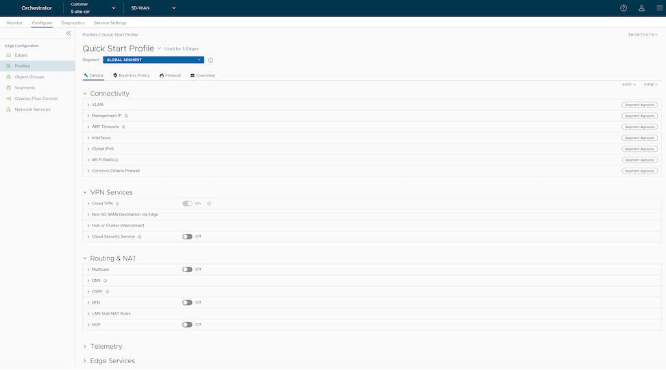
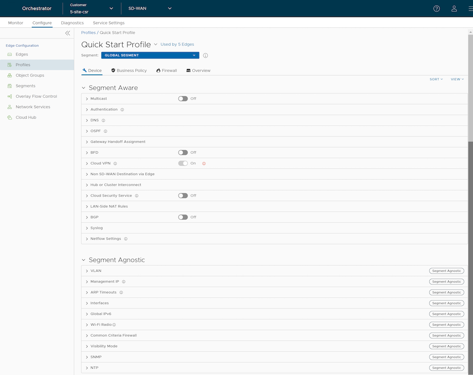
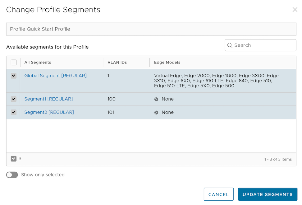
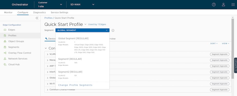
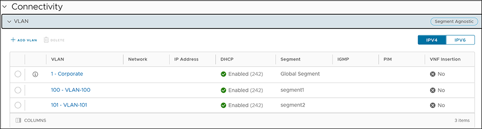
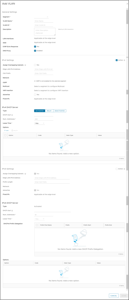

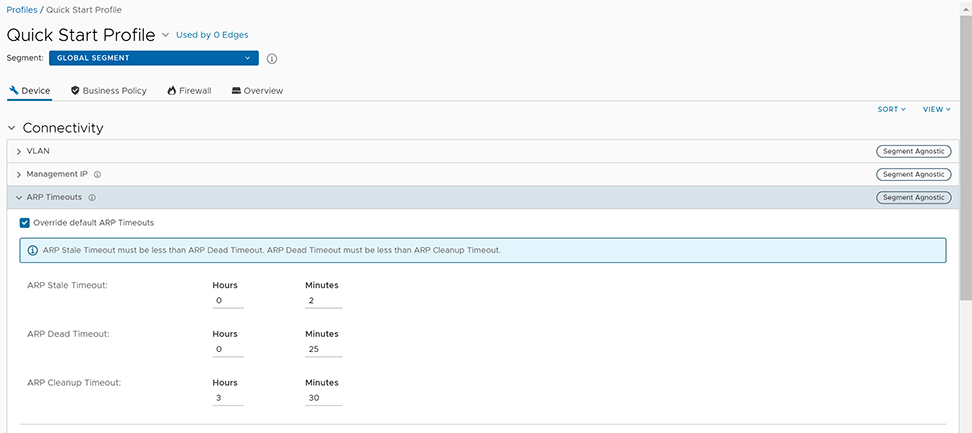
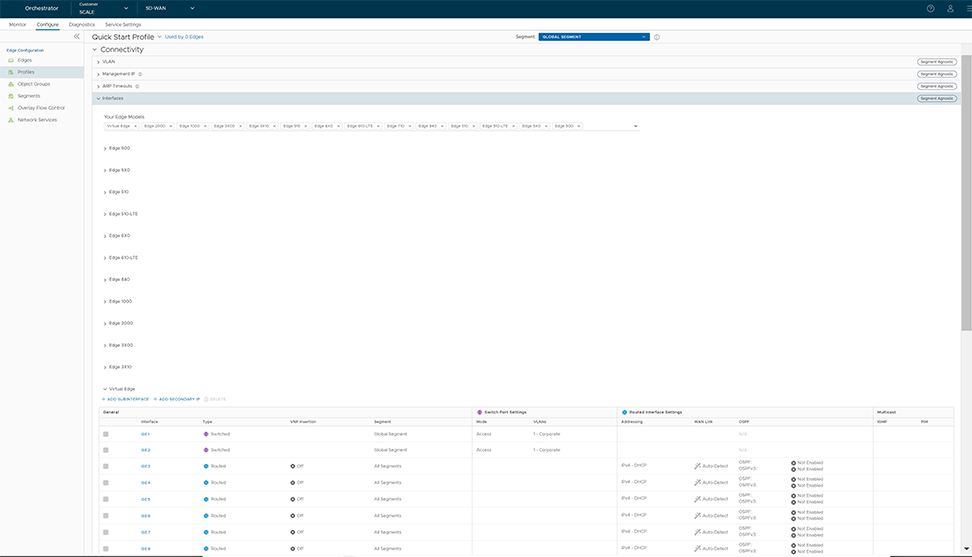
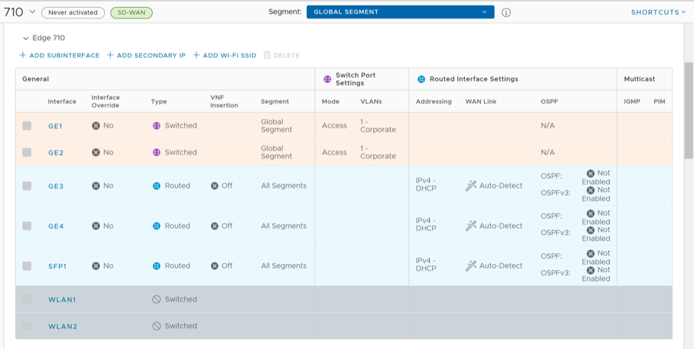
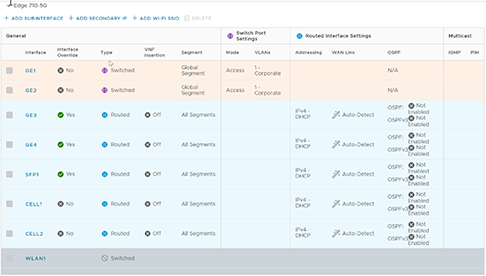
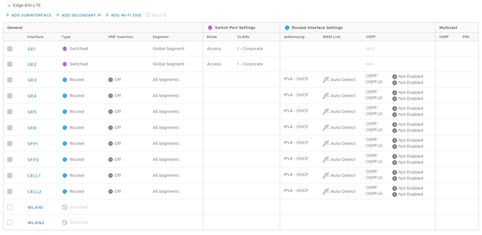
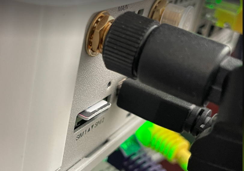

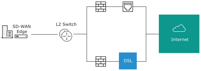

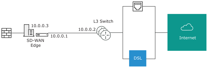
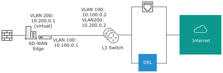
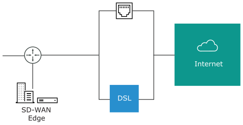
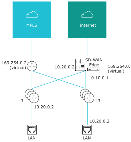
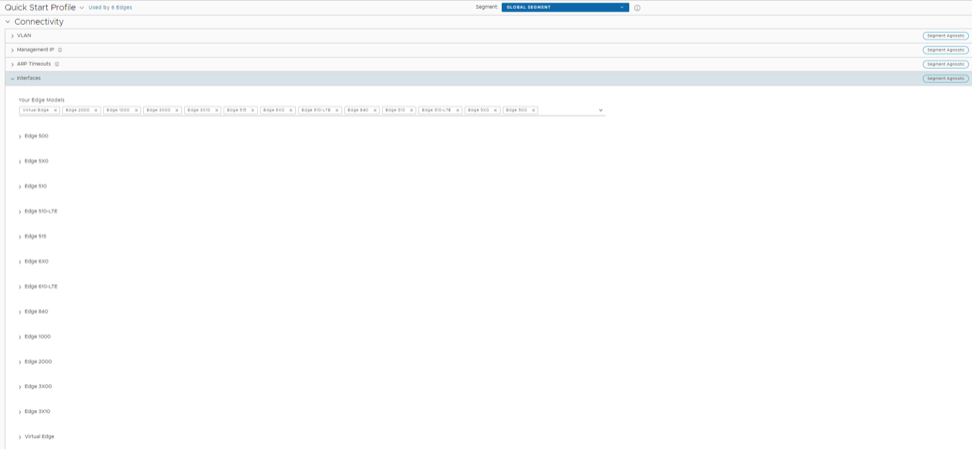
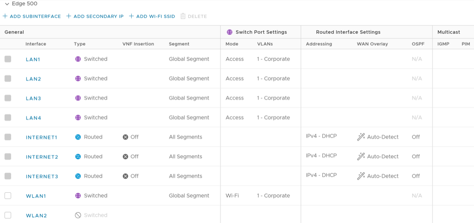
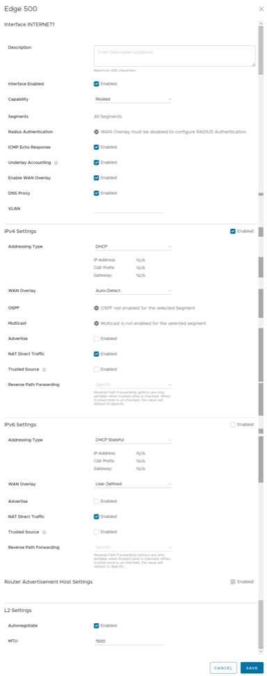
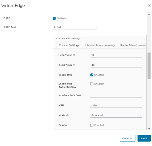 Note:For additional information on OSPF settings and OSPFv3, see Activate OSPF for Profiles.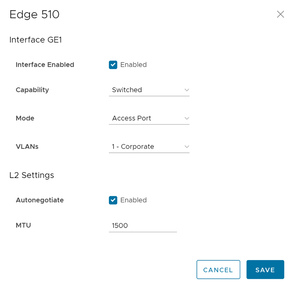
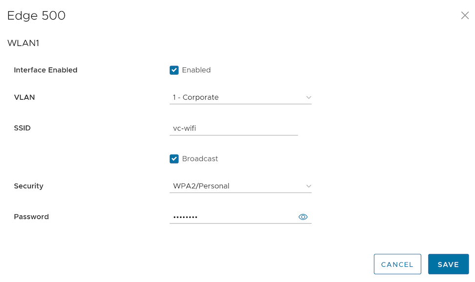

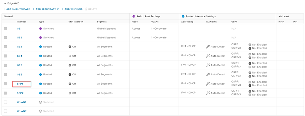
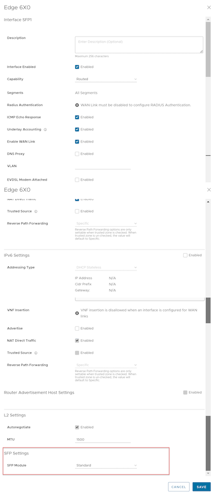
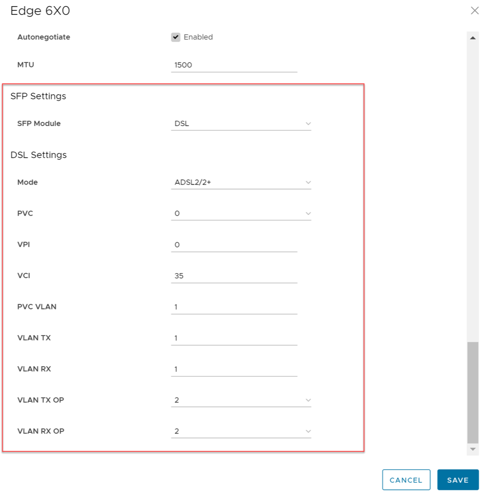
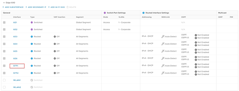
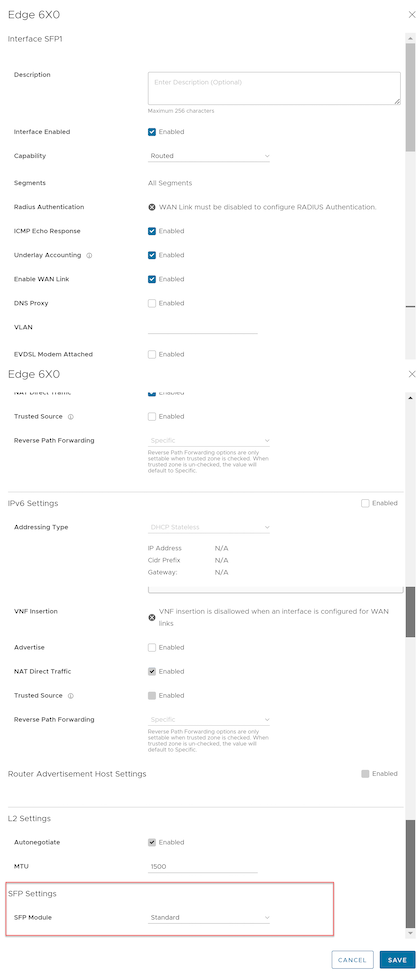
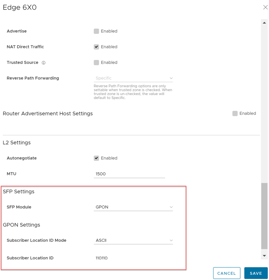
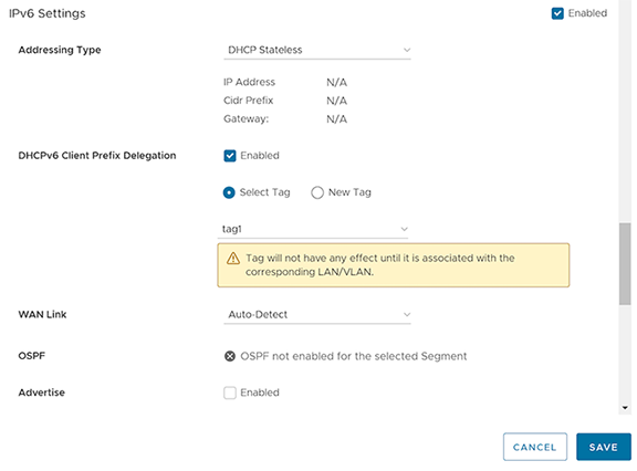
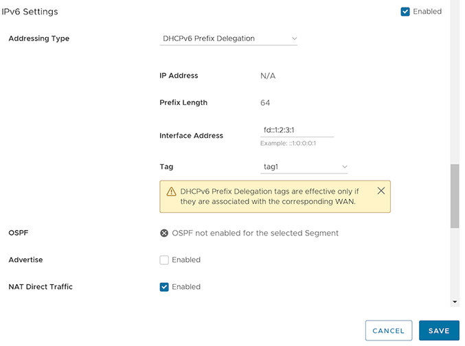
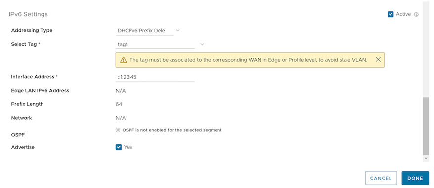
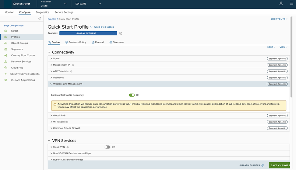
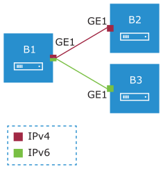
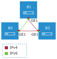
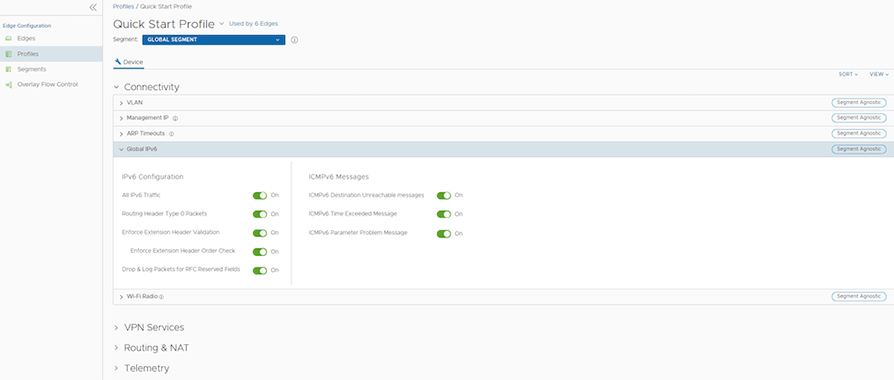
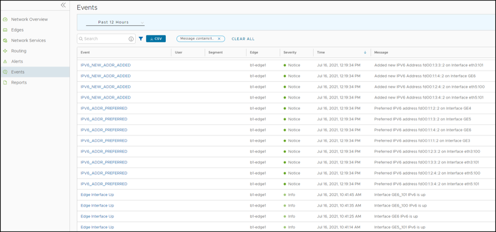
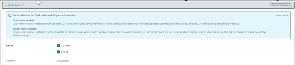
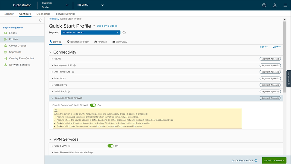
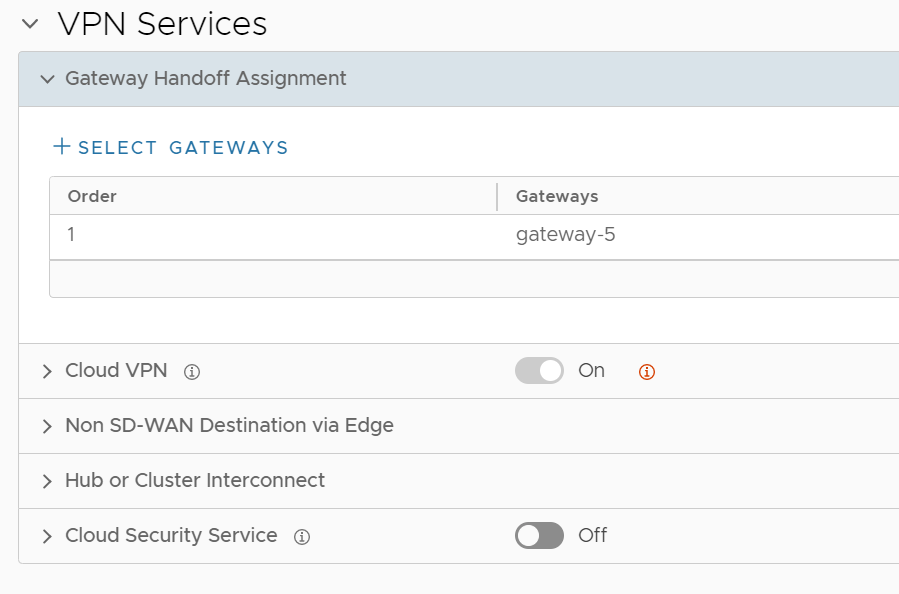

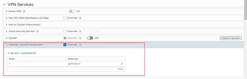
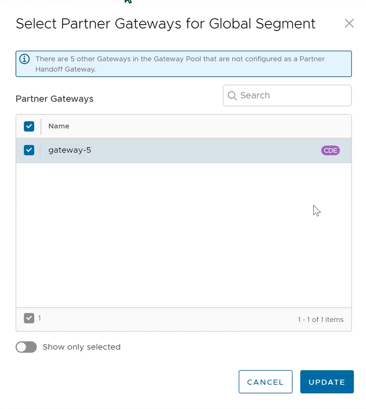
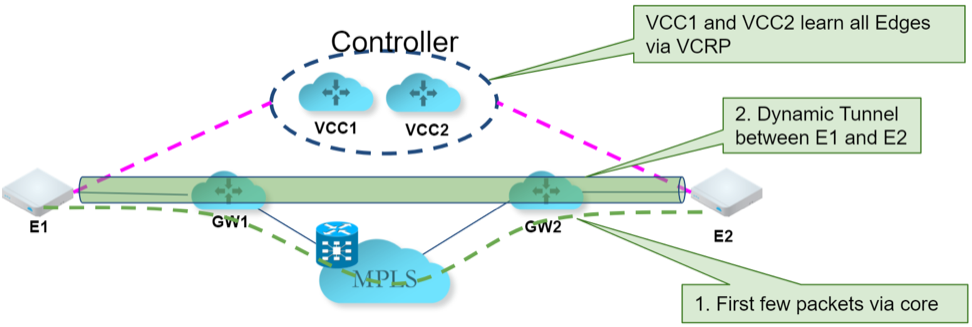
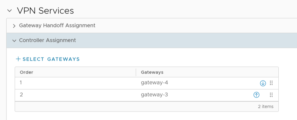
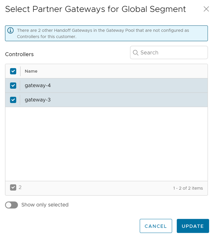
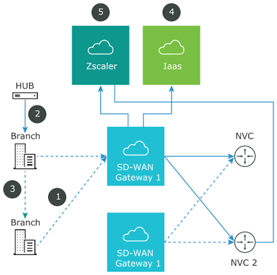
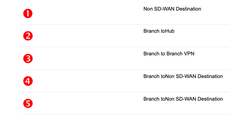
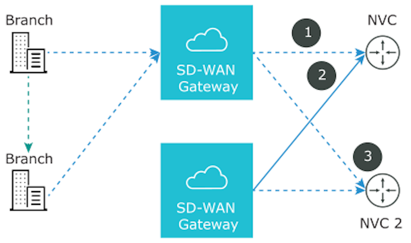
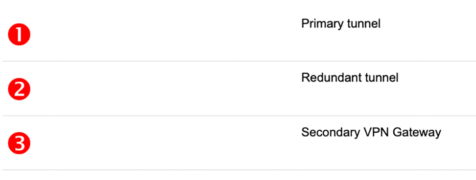
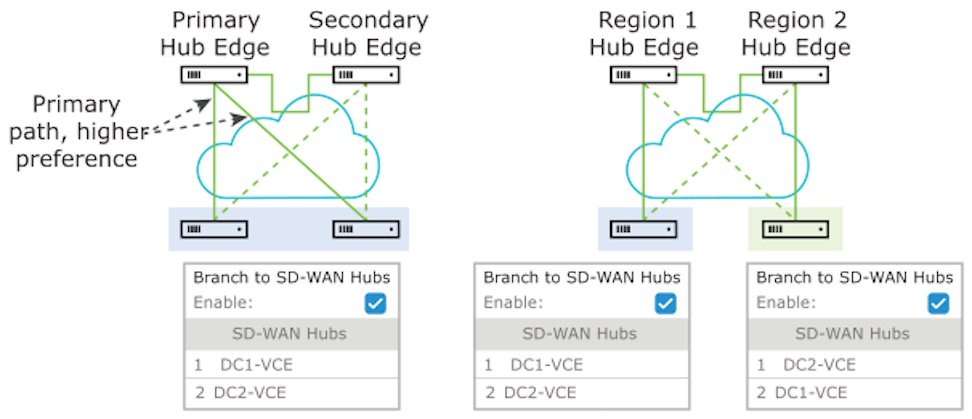
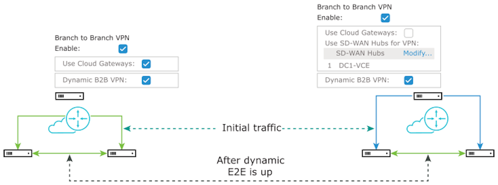
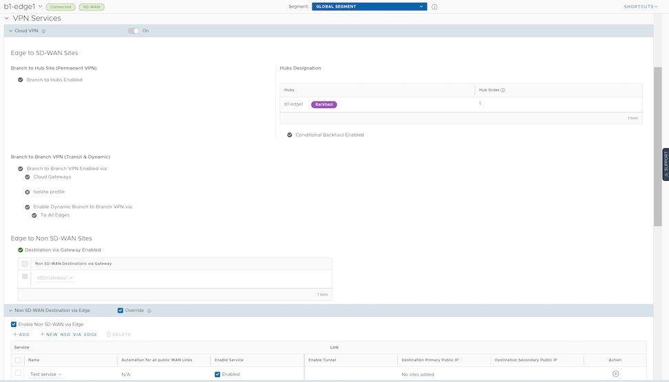 After activating Cloud VPN for a profile, configure any of the following Cloud VPN types: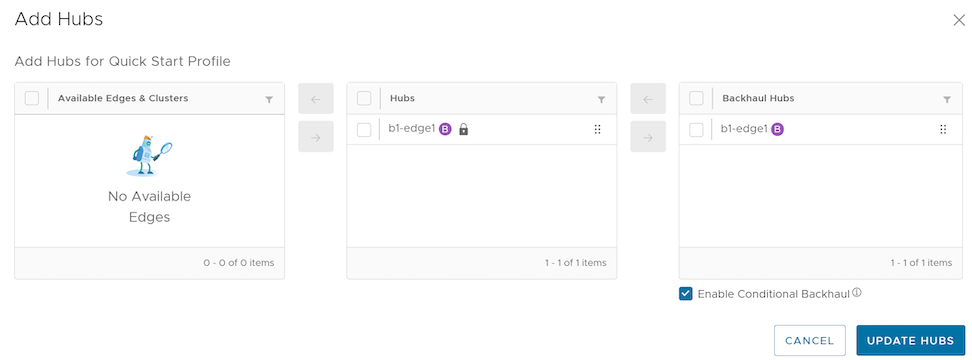
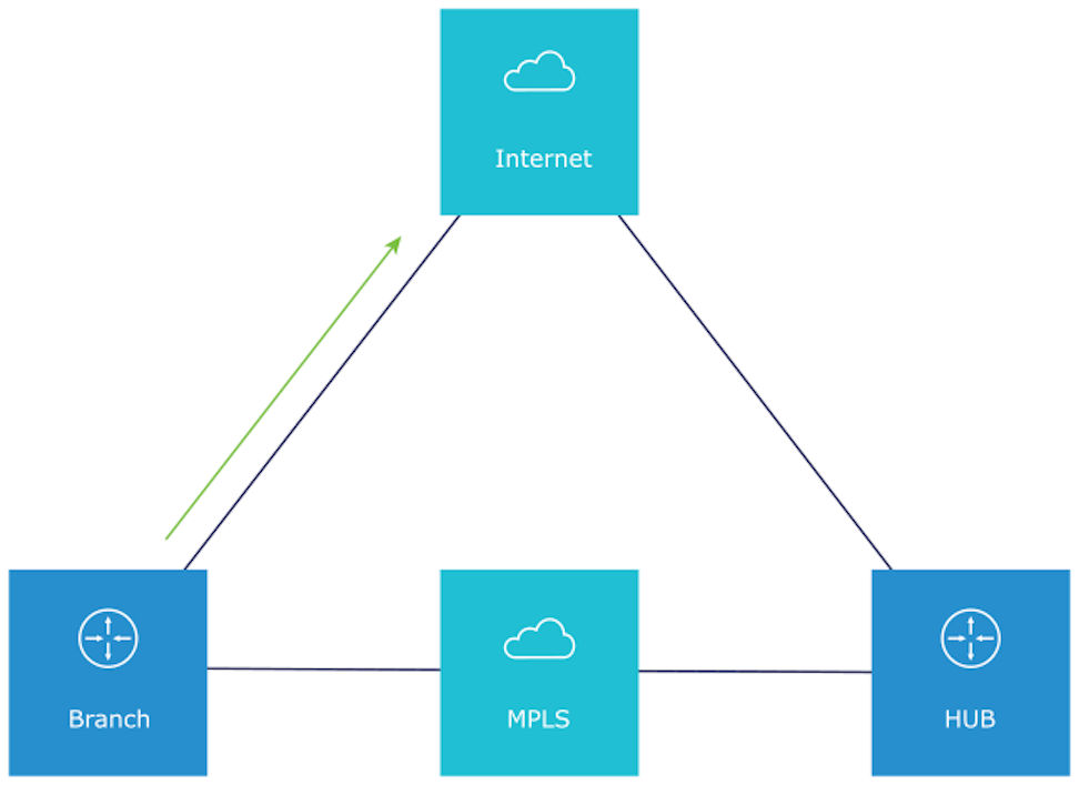
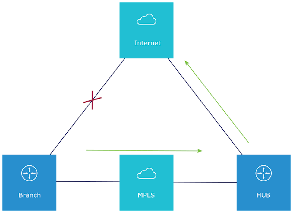
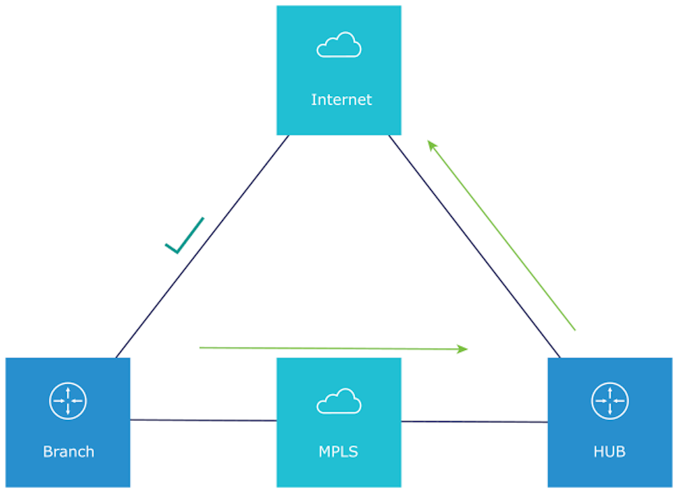
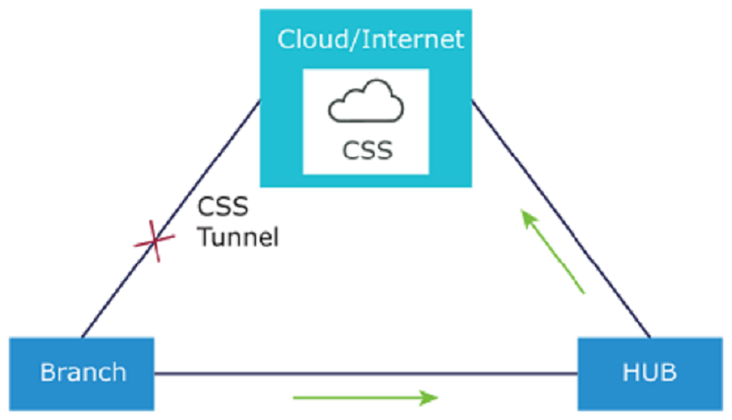
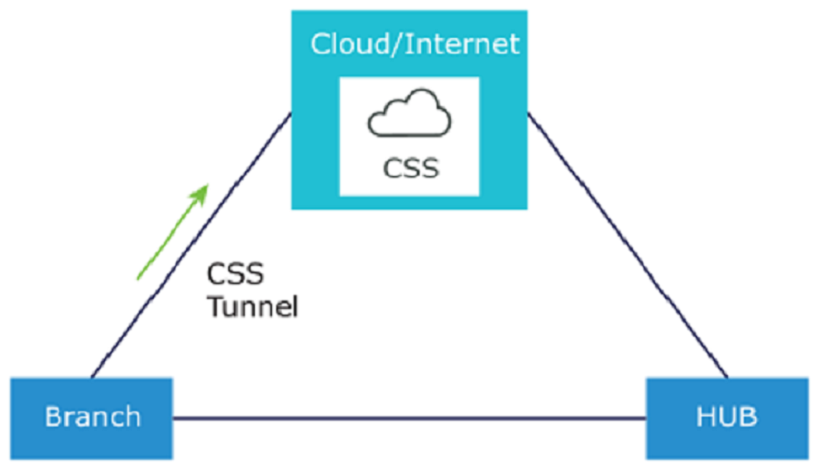
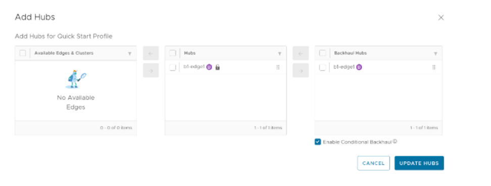
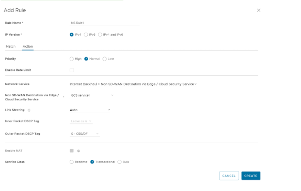 Note:
Note: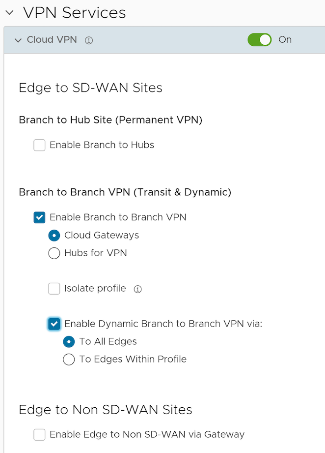
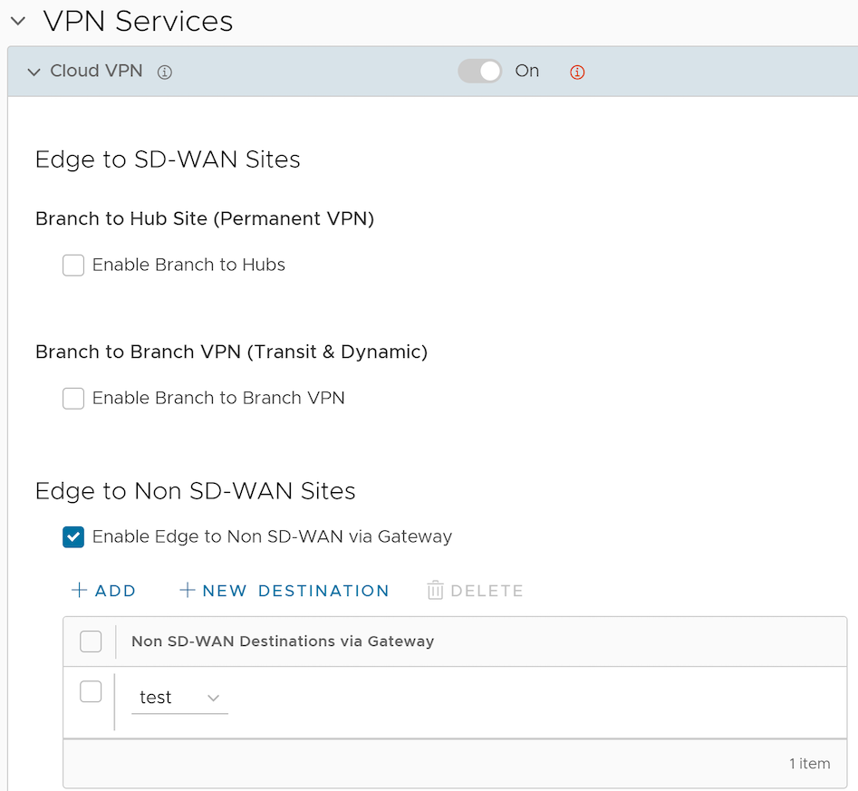
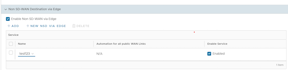
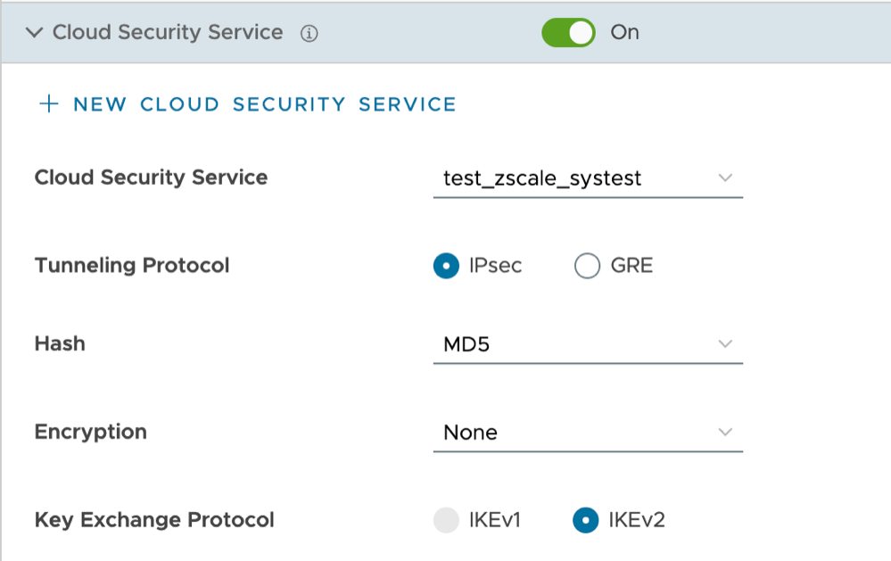
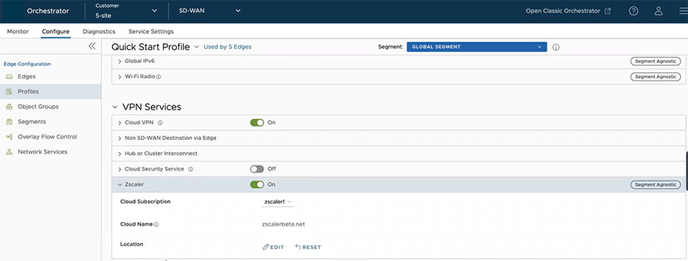
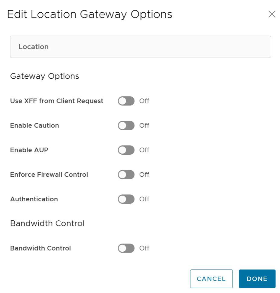
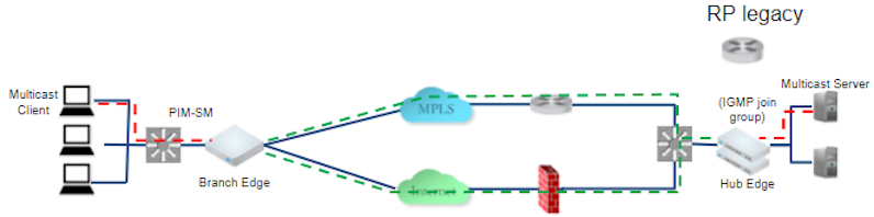
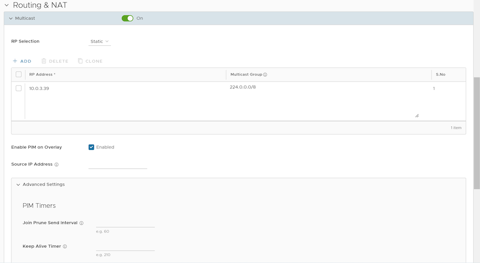
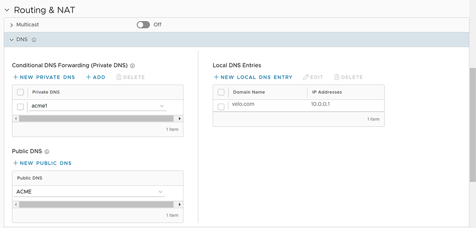
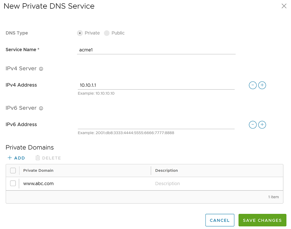 These are the available options for Private DNS:
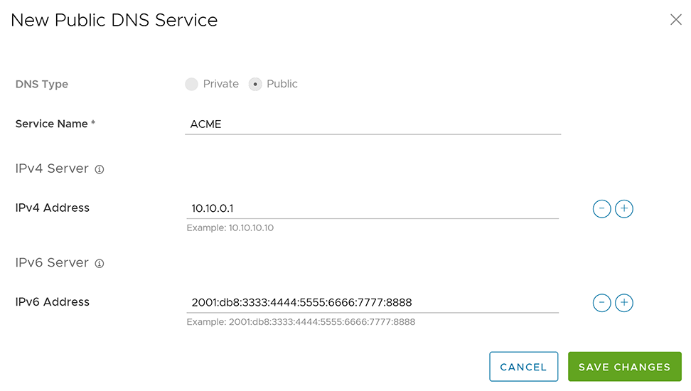 These are the available options for a new public DNS:
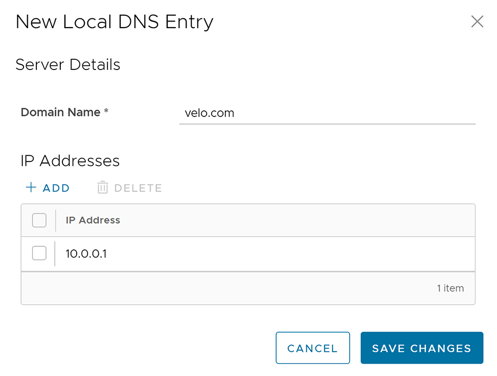 These are the available options for a new local DNS entry: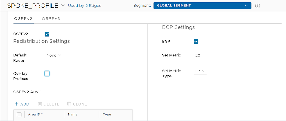
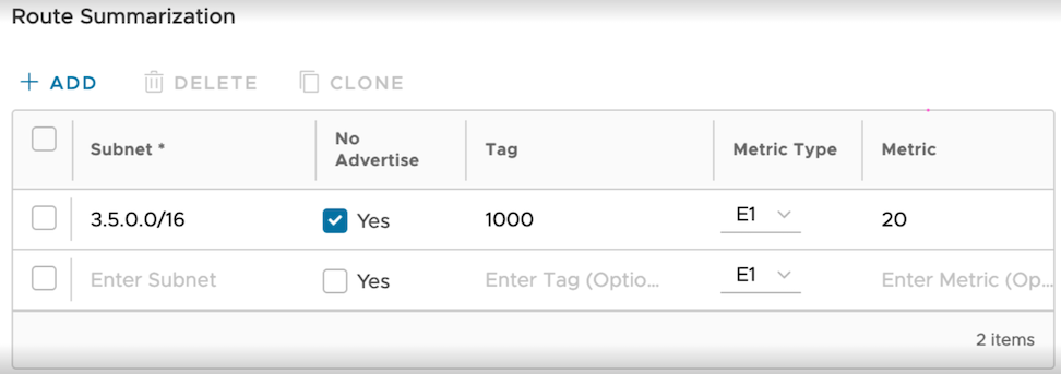
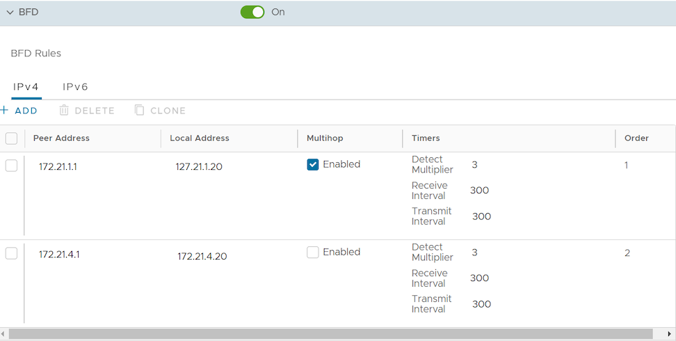
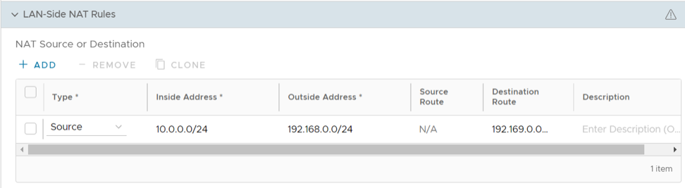
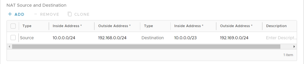 Important:If the Inside Prefix has a lesser value than the Outside Prefix, the feature supports Many:1 NAT in the LAN to WAN direction and 1:1 NAT in the WAN to LAN direction. For example, if the Source Type has an Inside Address with the value