
Configure Business Policy
VeloCloud provides an enhanced Quality of Service feature called Business Policy. Orchestrator allows users to configure business policy rules at the Profile and Edge levels. The business policy uses parameters such as source IP address/port, destination IP address/port, domain name, address and port group, applications, application categories, and DSCP tags to create business policy rules. Operators, Partners, and Admins of all levels can create a business policy.
This topic contains the following sections:
Configure Business Policies
The Business Policy tab allows users to configure rules at the Profile level. The system also supports overriding these Profile rules specifically at the Edge-level.
- Ensure that users have the details of IP addresses configured in the network devices.
- For an Enterprise user to configure the Customizable QoE settings, an Operator Super user must select the Customizable QoE checkbox by navigating to .
Business Policy Rules now support Segment-awareness. The Segment drop-down menu at the top of the screen lists all configurable Segments. By default, the system selects the Global Segment [Regular] Segment. When users choose a Segment from the menu, the Configure Business Policy area displays its associated settings and options. For additional information. see Configure Segments.
Configure Business Policy for a Profile
Arista examines traffic to identify application behavior, service objectives (High, Medium, or Low), and Edge WAN link conditions. Using these insights, the Business Policy optimizes application performance by managing queuing, bandwidth utilization, link steering, and network error mitigation.
- In the SD-WAN service of the Enterprise portal, go to . The Profiles page displays the existing Profiles.
- Go to the link to a Profile, and then select the Business Policy tab. Alternatively, users can select the View link in the Biz. Pol column of the Profile.
- The following screenshot displays the existing predefined business policy rules. The Configure Business Policy section displays the business policy rules listed in order of highest precedence. The system manages network traffic by identifying its characteristics and matching them to the rule with the highest precedence. Users can use the predefined rules or create custom ones by selecting the +ADD button.
Figure 1. Configure Business Policy 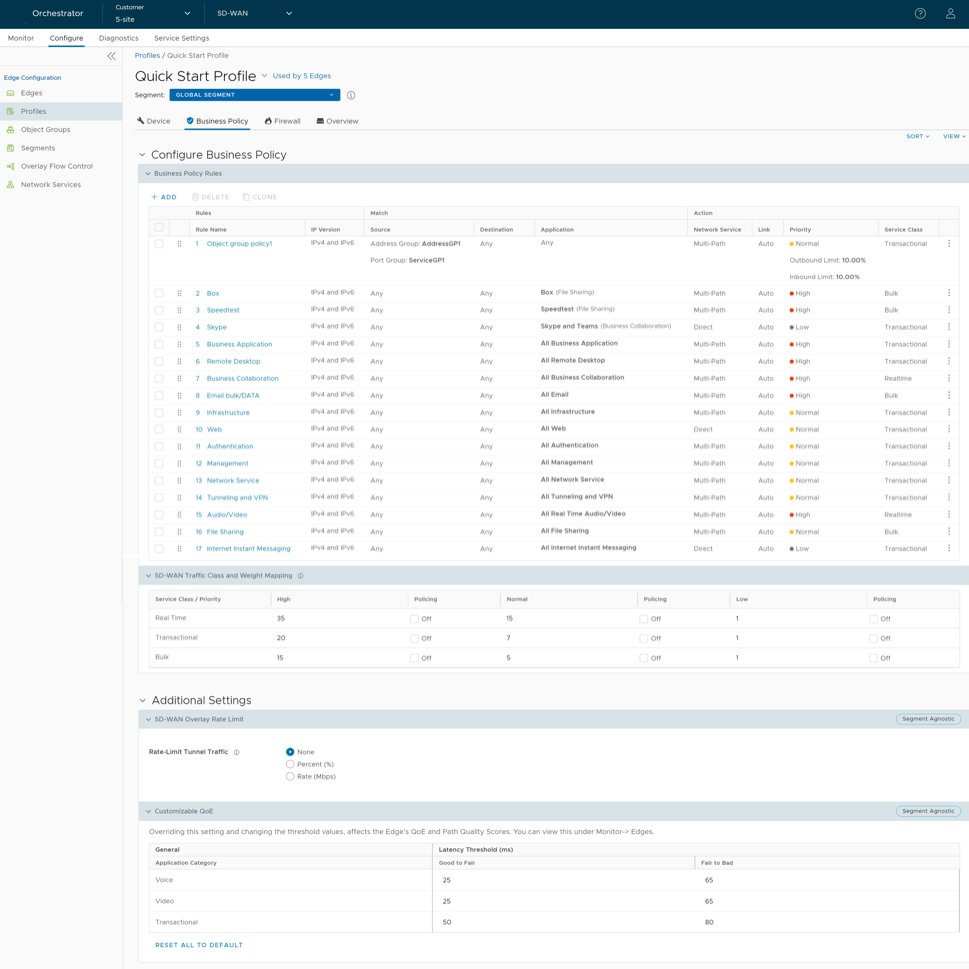
- Users can configure the following options:
Table 1. Configure Business Policy - Options and Descriptions Option Description Business Policy Rules Add Creates a new business policy. For additional information, see Create Business Policy Rule. Delete Deletes the selected business policies. Clone Duplicates the selected business policy. SD-WAN Traffic Class and Weight Mapping Defines traffic classes with specific priorities and service classes, and map their associated scheduler weights. For additional information, see Overlay QoS CoS Mapping. Additional Settings SD-WAN Overlay Rate Limit Configures rate limit for tunnel traffic. For additional information, see Tunnel Shaper for Service Providers with Partner Gateway. Customizable QoE Configures the minimum and maximum latency threshold values, in the range 1ms to 1000ms, for Voice, Video, and Transactional application categories. Selecting 'Reset All To Default' resets all values to their default settings. The following note lists the default values under the table. Sort Sort the business policy rules using the following options: - Sort by category
- Sort by segment aware
View From the View drop-down menu, select: - Expand All - Expands and displays all business policy-related details and settings.
- Collapse All - Collapses all business policy-related details and settings.
Note:- The default latency threshold values are:
The Good to Fair value must always be less than the Fair to Bad value.Table 2. Default Latency Threshold Values Application Category Good to Fair Fair to Bad Voice 25 65 Video 30 65 Transactional 50 80
- Modifying Customizable QoE values triggers an event on the page.
- Only Edge versions 5.2.0 and above support Customizable QoE configurations.
- Tunnels to a Gateway automatically inherit any threshold changes users apply to the associated Edge.
- Profiles automatically push configurations to all associated Edges. To customize a specific site, override these configurations or add unique business policy rules at the Edge level.
Configure Business Policy for an Edge
- In the SD-WAN service of the Enterprise portal, select . The Edges page displays the existing Edges.
- Go to the link to an Edge, and then select the Business Policy tab. Alternatively, users can select the View link in the Business Policy column of the Edge. The Configure Business Policy page appears.
Figure 2. Configure Business Policy 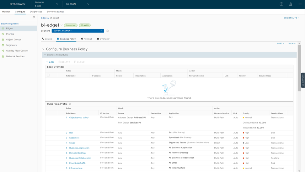
- The Rules From Profile section displays the business policy rules and settings that the Edge inherits from its associated Profile. To edit existing rules or add new ones for a specific Edge, select the Override checkbox. The Edge Overrides section then shows new and modified rules.
Create Business Policy Rule
The Business Policy steers traffic, manages bandwidth, and ensures Quality of Service (QoS) based on criteria like application, source, and destination. Operators, Partners, and Admins can create these policies to match parameters such as IP addresses, ports, and protocols. The Business Policy compares each data packet against the specified match conditions. When a packet matches these conditions, the system performs the associated actions. If a packet matches no parameters, the system applies a default action.
Before you begin:
Ensure that users have the details of the IP addresses of their network.
- In the SD-WAN service of the Enterprise portal, go to . The Profiles page displays the existing Profiles.
- Go to the link to a Profile or select the View link in the Device column of the Profile. The Device tab displays the configuration options.
- Select the Business Policy tab.
From the Profiles page, users can navigate to the Business Policy page directly by selecting the View link in the Biz.Pol column of the Profile.
- On the Business Policy page, select + ADD. It displays the Add Rule window.
Figure 3. Add Rule - Match Tab 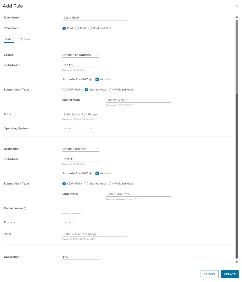
- Enter the Rule Name and select the IP version. Users can configure the Source and Destination IP addresses according to the selected IP version, as follows:
- IPv4 and IPv6 – Configures both IPv4 and IPv6 addresses in the matching criteria. In this mode, users can select IP addresses from Object Groups that contain both types of Address Groups. The system selects this address type by default.
- IPv4 – Applies to traffic with only IPv4 addresses as source and destination.
- IPv6 – Applies to traffic with only IPv6 addresses as source and destination.
Note:
- When users upgrade, the system moves Business Policy rules from previous versions to IPv4 mode.
- Symantec WSS integration supports only IPv4.
- On the Match tab, configure the match criteria for Source, Destination, and Application traffic.
Table 3. Match Tab - Options and Descriptions Option Description Source Specifies the source for packets. Select any of the following options: - Any- Allows all source addresses by default.
- Object Group- Allows to select a combination of address group and service group.
- The IPv4 address type matches the traffic source only against IPv4 addresses within the Address Groups.
- The IPv6 address type matches the traffic source only against IPv6 addresses within the Address Groups.
- The IPv4 and IPv6 address type matches the traffic source against both address versions within the Address Groups.
Note: The system ignores any domain names within the selected address group when matching the traffic source.Activate Pre-NAT- This option enables the business policy to match both pre-NAT and post-NAT IPv4 addresses for the LAN-side Source IP.Note: Pre-NAT functionality applies only to IPv4 and Mixed mode object groups and remains unavailable for IPv6 groups.For additional information, see Object Groups and Configure Business Policies with Object Group. - Define- This feature specifies source traffic by VLAN, Interface, IP Address, Port, or Operating System using the following parameters::
- VLAN: Matches traffic originating from the VLAN specified in the drop-down menu.
- Interface: Matches traffic from the interface specified in the drop-down menu.
Note: The menu disables interfaces that remain unactivated or unassigned to the current segment.
- IP Address- Matches traffic from a specified IPv4 or IPv6 address..
Note: This option remains unavailable in Mixed mode (IPv4 and IPv6). In Mixed mode, the system matches traffic based on the specified VLAN or Interface instead.Activate Pre-NAT- This option enables the business policy to evaluate both pre-NAT and post-NAT IPv4 addresses for the LAN-side Source IP.Note: Only IPv4 address matching supports the Pre-NAT option.The system matches source traffic using the IP address in conjunction with one of the following specific address types:
- CIDR prefix: Defines the network using a CIDR value (for example:
172.10.0.0/16). - Subnet mask: Defines the network using a standard Subnet mask (for example:
172.10.0.0 255.255.0.0). - Wildcard mask: Narrows policy enforcement to a set of devices across different IP subnets that share a matching host IP address value. The Wildcard mask matches an IP or set of addresses using an inverted subnet mask.
-
Logic: A binary
0in the mask fixes the corresponding bit value, while a binary1allows the value to vary. For example, a mask of0.0.0.255(binary00000000.00000000.00000000.11111111) used with IP172.16.0.0fixes the first three octets and allows the last octet to vary.Note:Only IPv4 addresses support this option.
- CIDR prefix: Defines the network using a CIDR value (for example:
- Ports- Matches traffic originating from the specified source port or port range.
- Operating System- Matches traffic based on the operating system identified in the drop-down menu.
Destination Specifies the destination for data packets using one of the following categories: - Any- Allows all destination addresses by default.
- Object Group- Combines a specific Address Group and Service Group for destination matching. Activate Pre-NAT enables the business policy to match both pre-NAT and post-NAT IPv4 addresses for the LAN-side Destination IP
Note: Pre-NAT Supports IPv4 and Mixed mode object groups but excludes IPv6 object groups.For additional information, see Object Groups and Configure Business Policies with Object Group.
- Define- Specifies matching criteria for destination traffic based on IP Address, Domain Name, Protocol, or Port. The system selects Any as the default matching category:
- Any- Matches all destination traffic.
- Internet- Matches all Internet traffic (traffic that does not match an SD-WAN Route) to the destination.
Note:Activate Pre-NAT- Selecting this option allows the business policy to match with both, pre-NAT and post-NAT IPv4 addresses, on the LAN side for the Source IP.
- This option remains unavailable when the IP version is set to Mixed mode (IPv4 and IPv6). In Mixed mode, the system matches traffic using either the specified VLAN or Interface instead.
- For Symantec WSS integration, users must select this option.
Note: The Pre-NAT option is applicable only for IPv4 address matching.Along with the IP address, users can specify the Subnet mask type and domain name to match the destination traffic. - Edge- Matches all traffic to an Edge.
- Non SD-WAN Destination via Gateway- Matches all traffic routed to a specified Non SD-WAN Destination through the Profile-associated Gateway. The Profile must include associated Non SD-WAN sites via Gateway for this matching rule to function.
- Non SD-WAN Destination via Edge- Matches all traffic to a specified Non SD-WAN Destination through the Edge, associated with an Edge or Profile. The Profile must include associated Non SD-WAN sites via Edge for this matching rule to function.
- Domain name- Matches traffic for the entire domain name or a portion of the domain name specified in the Domain Name field. For example,
\salesforce\will match traffic to \www.salesforce.\. - Protocol- Matches traffic for the specified protocol, selected from the drop-down menu. The supported protocols are: GRE, ICMP, TCP, and UDP.
Note: Mixed mode does not support ICMP.
- Ports- Matches traffic from the specified source port or port range.
Application Select one of the following options: - Any- Applies the business policy rule to any application by default.
- Define- Selects a specific application to apply the business policy rule. In addition, a DSCP value can be specified to match the traffic coming in with a preset DSCP/TOS tag.
Note:- Business policy rules require the Deep Packet Inspection (DPI) Engine to apply Network Service Actions. Because the DPI Engine typically requires 5–10 packets to identify an application, the system cannot classify the initial packets in a flow. During this phase, unclassified traffic matches a less specific business policy, which often directs the traffic along an alternative path—such as Direct instead of Multipath—based on broader criteria.
Once the DPI Engine identifies the application, the system matches the traffic to a specific policy. The existing flow, however, maintains the original path to prevent session disruption. Consequently, the initial flow to a specific destination IP and port follows one path while the system populates the application cache. Subsequent flows to that destination then follow the path defined in the more specific application policy.
- Upon classification, the DPI Engine adds the Destination IP and port to the application cache, allowing the system to classify all subsequent flows immediately. Application cache entries expire after 10 minutes of inactivity. Once an entry expires, the next flow must undergo DPI re-identification, during which the flow may follow an alternative path until the DPI Engine confirms the application type.
- The Action tab specifies the operations the system executes when traffic matches the defined criteria.
Note: Depending on user's Match choices, some Actions may not be available.
Figure 4. Add Rule - Action Tab 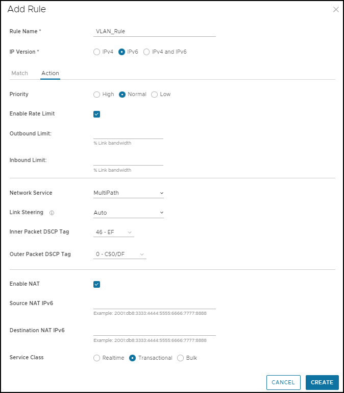
Table 4. Action Tab - Options and Descriptions Option Description Priority The Priority setting classifies the rule into one of the following tiers to determine resource allocation: - High
- Normal
- Low
Enable Rate Limit Select the Enable Rate Limit checkbox to set limits for inbound and outbound traffic directions. Note: The system performs rate limiting on a per-flow basis. Upstream rate limiting functions only when the Business Policy specifies a specific link or Edge interface.Setting the Steering option to Auto, Transport, or Group applies the rate limit to the aggregate bandwidth of all corresponding links. This configuration may prevent strict rate limit enforcement. For strict bandwidth enforcement, the Business Policy must steer traffic to a single specific link or Edge interface.
Network Service Set the Network Service to one of the following options: - Direct- Sends the traffic out of the WAN circuit directly to the destination, bypassing the Gateway.
Note: The Edge prioritizes secure routes over Business Policy rules by default. Consequently, the Edge forwards traffic via Multipath (Branch-to-Branch or Cloud-via-Gateway) even when a Business Policy specifies a Direct path, provided the Edge receives secure default or specific routes from a Partner Gateway or another Edge.
The Secure Default Route Override feature modifies this behavior for Partner Gateway secure routes. Activating this feature at the customer level allows the Business Policy to supersede matching Partner Gateway secure routes. This override applies specifically to Partner Gateway routes and does not affect Hub secure routes.
- Multi-Path- Sends the traffic from one Edge to another Edge.
- Internet Backhaul- This network service activates only when the Destination is set to Internet.
Note: The Internet Backhaul Network Service only applies to Internet traffic (WAN traffic destined to network prefixes that do not match a known local route or VPN route).For information about these options, see Configure Network Service for Business Policy Rule.
Activation of Conditional Backhaul at the profile level applies the behavior to all associated Business Policies by default.
The Turn off Conditional Backhaul checkbox overrides this inheritance, excluding specific traffic (Direct, Multi-Path, and CSS) from the backhaul behavior. For additional information about how to activate and troubleshoot the Conditional Backhaul feature, see Conditional Backhaul.
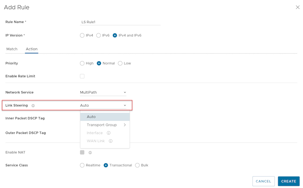
Link Steering Select one of the following link steering modes: - Auto- Automatic Link Steering serves as the default mode for all applications. In this mode, Dynamic Multi-Path Optimization (DMPO) selects the optimal links based on application requirements and activates on-demand remediation as network conditions dictate.
- Transport Group- This steering policy applies a unified Business Policy across diverse device types or locations, regardless of local WAN carriers or physical interfaces. The policy utilizes one of the following transport group options:
- Public Wired
- Public Wireless
- Private Wired
- Interface- Link steering is tied to a physical interface and will be used primarily for routing purposes.
Note: This option is only applicable at the Edge override level.
- WAN Link- Defines policy rules based on specific private links. In this mode, the WAN link configuration remains separate and distinct from the Interface configuration. The system supports selection of both manually configured and auto-discovered WAN links. This option applies exclusively at the Edge override level.
- Transport Group- This steering policy applies a unified Business Policy across diverse device types or locations, regardless of local WAN carriers or physical interfaces. The policy utilizes one of the following transport group options:
- Inner Packet DSCP Tag- Select an Inner Packet DSCP Tag from the drop-down menu.
- Outer Packet DSCP Tag- Select an Outer Packet DSCP Tag from the drop-down menu
Note: Configuring the Network Service as Direct excludes IPv6-only Interfaces and IPv6-only WAN links from Link Steering support.For additional information about the link steering modes and DSCP, DSCP marking for both Underlay and Overlay traffic, see Configure Link Steering Modes.Enable NAT Activate or deactivate NAT. This option is not available for IPv4 and IPv6 mode. For additional information, see Configure Policy-based NAT. Service Class Select one of the following Service Class options. Apps/Categories fall in one of these categories: - Real-time
- Transactional
- Bulk
Note: This option is only for a custom application. - Selecting Create generates the business policy rule for the designated Profile. The new rule populates within the Business Policy Rules section of the Profile Business Policy page.
Note: Edge-level configurations cannot update rules inherited from the Profile. Overriding a Profile-level rule requires the creation of an identical rule at the Edge level with new parameters; the Edge-level rule then supersedes the Profile configuration.IPv6 and Mixed mode (IPv4 and IPv6) support rule creation exclusively through the Orchestrator. All other operations, including Update and Delete, require the API.
Related Information: Overlay QoS CoS Mapping
Configure Network Service for Business Policy Rule
While creating or updating a Business Policy rule and action, users can set the Network Service to Direct, Multi-Path, and Internet Backhaul.
Direct
The system forwards traffic out of the WAN circuit directly to the destination and bypasses the Gateway. Network Address Translation (NAT) applies to this traffic only when the administrator enables the NAT Direct Traffic checkbox within the Interface Settings on the Device tab.
The following functional limitations govern NAT Direct Traffic.
The system performs NAT only when the traffic matches a route in the Edge routing table where the Next Hop is either Cloud VPN or Cloud Gateway. Regardless of any Business Policy configurations that include private IP destinations, NAT applies exclusively to traffic destined for public IP addresses.
Multi-Path
It sends the traffic from one Edge to another Edge, and from an Edge to a Gateway.
Internet Backhaul
Defining the Destination as Internet within the business policy rule match criteria enables the Internet Backhaul network service.
- Backhaul Hubs
- Non SD-WAN Destinations via Gateway
- Non SD-WAN Destinations via Edge/Cloud Security Service
Note: NSD via Edge and CSS does not support mixed IP mode (IPv4 and IPv6).
- VeloCloud SD-WAN supports the interconnection of multiple Hub Edges or Hub Clusters to extend the reach of communicating Spoke Edges. The Hub or Cluster Interconnect feature enables communication between Spoke Edges connected to different Hubs or Clusters via multiple overlay and underlay connections. For additional information, see Hub or Cluster Interconnect.
Configuring multiple VeloCloud Sites for backhaul supports the redundancy inherent in the Non SD-WAN Destination connection while maintaining consistent behavior: the system drops traffic if the service becomes unavailable.
Configure Network Service Rule
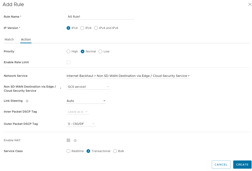
Enabling Conditional Backhaul at the profile level applies this behavior by default to all Business Policies within that profile. The administrator may deactivate conditional backhaul for specific policies to exclude selected traffic (Direct, Multi-Path, and CSS) by selecting the Turn off Conditional Backhaul checkbox in the Action area of the Configure Rule screen.
For additional information about how to enable and troubleshoot the Conditional Backhaul feature, see Conditional Backhaul.
Configure Link Steering Modes
The Business Policy allows the configuration of link steering through several distinct modes.
To create or configure a Business Policy, see Create Business Policy Rule.
Automatic Link Selection
By default, all applications receive the automatic Link steering mode. This means the DMPO automatically selects the best links based on the application type and automatically enables on-demand remediation when necessary. There are four possible combinations of Link Steering and On-demand Remediation for Internet applications. Traffic within the Enterprise (VPN) always goes through the DMPO tunnels, and always receives the benefits of on-demand remediation.
| Scenario | Expected DMPO Behavior |
|---|---|
| At least one link satisfies the SLA for the application. | Choose the best available link. |
| Single link with packet loss exceeding the SLA for the application. | Enable FEC for the real-time applications sent on this link. |
| Two links with loss on only one link. | Enable FEC on both links. |
| Multiple links with loss on multiple links. | Enable FEC on two best links. |
| Two links but one link appears unstable, i.e. missing three consecutive heartbeats. | Mark link unusable and steer the flow to the next best available link. |
| Jitter and Loss on both links. | The system enables Forward Error Correction (FEC) on both links and activates the Jitter buffer on the receiving side. The Jitter buffer triggers when jitter exceeds 7 ms for voice or 5 ms for video.
The sending DMPO endpoint notifies the receiving DMPO endpoint to activate the Jitter buffer. The receiving DMPO endpoint then buffers up to 10 packets or 200 ms of traffic, whichever occurs first. To calculate the flow rate for the de-jitter buffer, the receiving DMPO endpoint uses the original timestamp embedded in the DMPO header. If the sender does not transmit the flow at a constant rate, the system does not enable Jitter buffering. |
Link Steering by Transport Group
A Transport Group represents WAN links bundled together based on similar characteristics and functionality. Defining a Transport Group allows business abstraction so that a similar policy can apply across different Hardware types.
Different locations may use different WAN transports, for example, WAN carrier names and WAN interface names. DMPO uses the concept of Transport Group to abstract the underlying WAN carriers and interfaces from the Business Policy configuration. The Business Policy configuration can specify the transport group, such as Public Wired, Public Wireless, or Private Wired, in the steering policy so that the same Business Policy configuration can apply across different device types or locations, which may have completely different WAN carriers and WAN interfaces. When the DMPO performs the WAN link discovery, it also assigns the transport group to the WAN link. It is the desirable option for specifying the links in the Business Policy because it eliminates the need for IT administrators to know the type of physical connectivity or the WAN carrier.
For this option, the link steering ties to a physical interface. Routing primarily uses link-state routing over the Internet. However, even though it should logically be used only for routing traffic directly from the VeloCloud Site, if the rule specifies a Network Service that requires Internet Multi-path benefits, it will pick a single WAN link connected to the interface.
If users choose the Preferred option, the Error Correct Before Steering checkbox displays. If users select the checkbox, an additional Loss% variable becomes available. If not enabled, the Edge starts steering traffic away if the link loss exceeds the application SLA; for example, the Real-Time application SLA is 0.3% by default. With Error Correct Before Steering applied and a Loss percentage defined (4% in this example), the Edge continues to use the selected link or transport group and applies error correction until loss reaches 4%, at which point it steers traffic to another path. If users do not select this checkbox, the application steers traffic before Error Correction occurs.
The system allows this option only at the Edge override level. This restriction ensures that the provided link options always match the specific Edge hardware model.
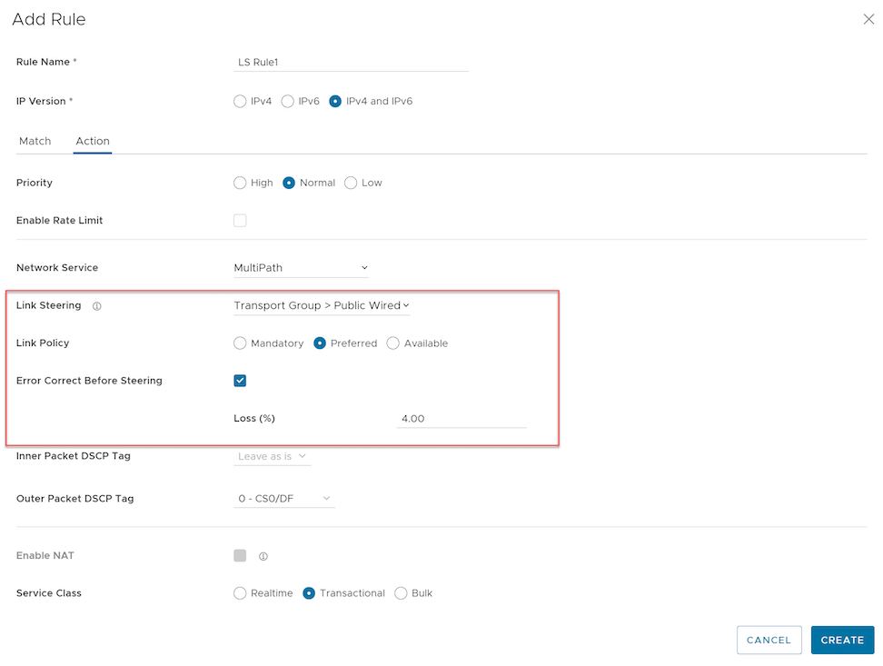
The system allows this option both at the Edge override level and Profile level.
Link Steering by Interface
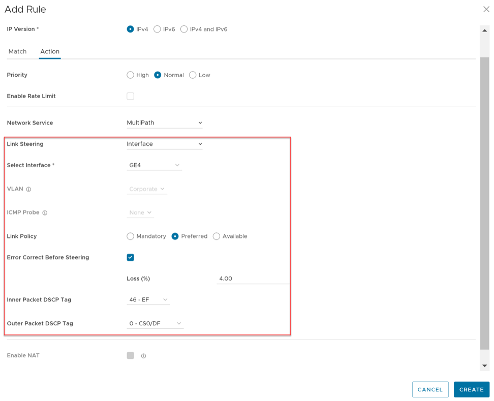
This steering option ties the link to a physical interface, primarily for routing purposes. Although the system logically uses this setting to route traffic directly from the VeloCloud Site, any rule requiring Internet Multi-path benefits will instead select a single WAN link connected to that interface.
Choosing the Preferred option displays the Error Correct Before Steering checkbox. Selecting this checkbox makes an additional Loss% variable available. Without this setting, the Edge steers traffic away once link loss exceeds the application SLA (such as the 0.3% default for Real-Time applications).
With Error Correct Before Steering active and a defined Loss percentage (e.g., 4%), the Edge maintains the selected link or transport group and applies error correction until loss reaches the 4% threshold. Only then does the Edge steer traffic to another path. If the administrator leaves this checkbox unselected, the application steers traffic before error correction occurs.
The system allows this configuration only at the Edge override level. This restriction ensures that the provided link options always match the specific Edge hardware model.
WAN Link
For this option, the interface configuration is separate and distinct from the WAN link configuration. Select a WAN link that was either manually configured or auto-discovered.
WAN Link Menu
Users can define policy rules based on specific private links. If users have created private network names and assigned them to individual private WAN overlays, these private link names display in the WAN Link menu.
For information on how to define multiple private network names and assign them to individual private WAN overlays, see Configure Private Network Names.
If users select the Preferred option, the Error Correct Before Steering checkbox displays. If users do not select this checkbox, the application steers traffic before Error Correction occurs.
The system allows this option only at the Edge override level.
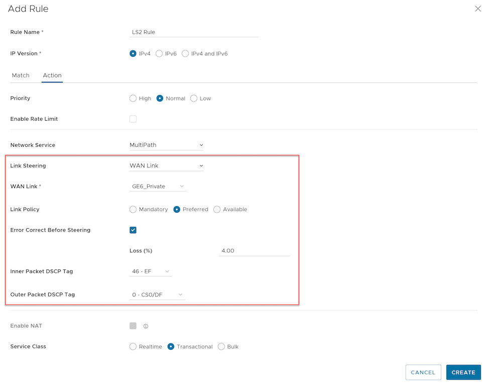
For the Interface and WAN Link choices, users must select one of the following options:
| Option | Description |
|---|---|
| Mandatory | This setting indicates that the system sends traffic over the specified WAN link or Link Service-group. If the specified link (or every link within the chosen service group) becomes inactive, or if a Multi-path gateway route remains unavailable, the system drops the corresponding packet. |
| Preferred | This setting indicates that the system preferably sends traffic over the specified WAN link or link Service-group. If the specified link (or all links within the chosen service group) becomes inactive, the chosen Multi-path gateway route becomes unstable, or the link fails to meet the Service Level Objective (SLO), the system steers the corresponding packet to the next best available link. Once the preferred link becomes available again, the system steers the traffic back to that original path. |
| Available | This setting indicates that the system preferably sends traffic over the specified WAN link or link Service-group as long as it remains available, regardless of the link SLO. If the specified link (or all links within the chosen service group) becomes unavailable, or if the selected Multi-path gateway route fails, the system steers the corresponding packet to the next best available link. Once the preferred link becomes available again, the system steers the traffic back to that path |
Link Steering and DSCP Marking for Underlay and Overlay Traffic Overview
VeloCloud SD-WAN supports DSCP remarking of packets forwarded by the Edge to the Underlay. The Edge can re-mark underlay traffic forwarded on a WAN link as long as users enable Underlay Accounting on the interface. The administrator enables DSCP re-marking within the Link Steering area of the Business Policy configuration. See Create Business Policy Rule. The example assumes that the Edge connects to MPLS and forwards both underlay and overlay traffic over that circuit. If the traffic matches the network prefix 172.16.0.0/12, the Edge re-marks the underlay packets with a DSCP value of 16 (CS2) and ignores the Outer Packet DSCP Tag field. For overlay traffic matching the same business policy, the system sets the DSCP value for the outer header to the value specified in the Outer Packet DSCP tag.

Link Steering and DSCP Marking for Underlay Traffic Use Case
Edges connecting to MPLS normally mark the DSCP on the packet before transmission to the PE, ensuring the Service Provider treats the packet according to the SLA. The administrator must enable Underlay Accounting on the WAN interface for Business Policy DSCP marking to take effect on underlay traffic.
Configure Link Steering with Underlay DSCP
- To verify that Underlay Accounting activates WAN Overlay by default, navigate to in the Orchestrator and select an specific Edge model.
Figure 11. Underlay Accounting 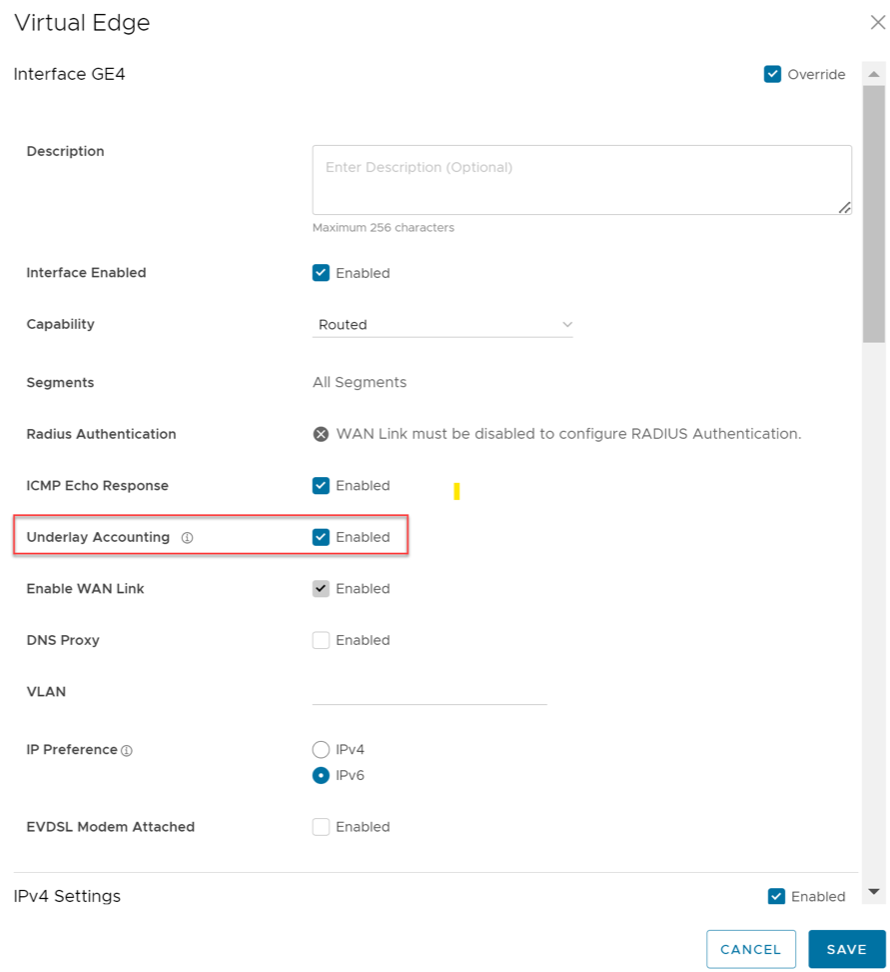
- From the SD-WAN service of the Enterprise portal, go to .
- From the Business Policy screen, select an existing rule or select +ADD to create a new rule.
- In the Action section, go to the Link Steering area.
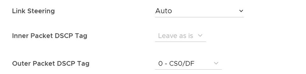
- Select one of the following as applicable: Auto, Transport Group, Interface, or WAN Link.
- Configure the Action criteria for the underlay traffic and configure Inner Packet DSCP Tag.
Linking Steering with Overlay DSCP Configuration
- To verify that Underlay Accounting activates WAN Overlay by default, navigate to in the Orchestrator and select an specific Edge model.
- From the SD-WAN service of the Enterprise portal, go to .
- From the Business Policy screen, select an existing rule or select +ADD to create a new rule.
- In the Action section, go to the Link Steering area.
- Select one of the following as applicable: Auto, Transport Group, Interface, or WAN Link.
- Configure Action criteria for the Overlay traffic and configure Inner Packet DSCP Tag and Outer Packet DSCP Tag.
Configure Policy-based NAT
The system supports the configuration of Policy-based NAT for both Source and Destination. This NAT applies to either Non SD-WAN Destination traffic or Partner Gateway Handoff traffic using Multi-path.
To configure NAT, the administrator defines the specific traffic and the intended action. The system offers two NAT configuration types: Many-to-One and One-to-One.
Accessing NAT
Users can access the NAT feature from , select +ADD, and then navigate to Action. Rules on a Non SD-WAN Gateway Destination via a Gateway allow NAT and allow Internet rules using Multipath.
Many-to-One NAT Configuration
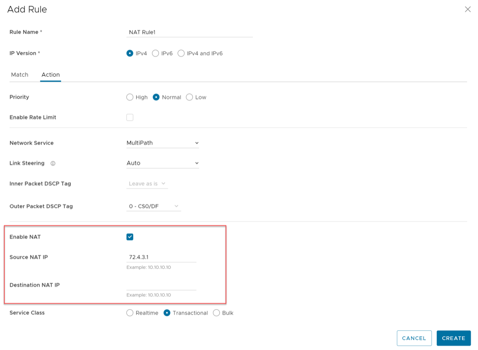
In this configuration, users can NAT the traffic's source or destination IP originated from the hosts behind the Edge to a different unique source or destination IP address. For example, the user can source NAT all the flows destined to a host or server in the Data Center, which is behind the Partner Gateway with a unique IP address, even though they are originated from different hosts behind an Edge.
The following figure shows an example of the Many to One configuration. In this example, all the traffic originating from the hosts that are connected to VLAN Corporate (behind the Edge destined to an Internet host or a host behind the DC) will get source NAT with the IP address 72.4.3.1.
One-to-One NAT Configuration
In this configuration, the Branch Edge maps a single local IP address of a host or server to a global IP address. When a host in the Non SD-WAN Destination or Data Center sends traffic to that global IP address, the Gateway forwards the traffic to the local IP address of the host or server in the Branch.
Overlay QoS CoS Mapping
A Traffic Class comprises a combination of Priority (High, Normal, or Low) and Service Class (Real-Time, Transactional, or Bulk), creating a 3x3 matrix of nine distinct classes. The administrator maps specific Applications/Categories and scheduler weights onto these Traffic Classes. The system then applies aggregate Quality of Service (QoS) treatment—including Scheduling and Policing—to all applications within a single Traffic Class.
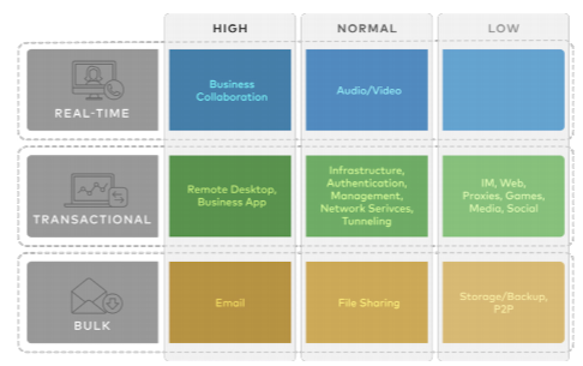
The Business Policy includes Smart Defaults functionality, which maps more than 2,500 applications to Traffic Classes. This feature enables application-aware QoS without requiring the manual definition of a policy. The system assigns a default weight to each Traffic Class in the Scheduler, though the administrator can modify these parameters in the Business Policy. The list below details the default values for the 3x3 matrix and its nine Traffic Classes.
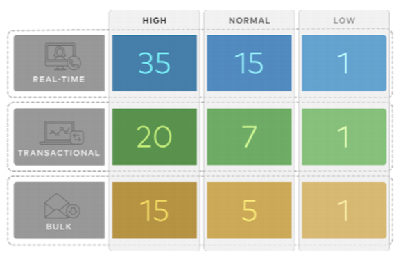
Example
In this example, a customer utilizes a 90 Mbps Internet link and a 10 Mbps MPLS link on the Edge, totaling 100 Mbps of aggregate bandwidth. Based on the default weight and Traffic Class mapping, applications mapping to Business Collaboration receive 35 Mbps of guaranteed bandwidth, while Email applications receive 15 Mbps.
The system allows the definition of business policies for an entire category (e.g., Business Collaborations), specific applications (e.g., Skype for Business), or granular sub-applications (e.g., Skype File Transfer, Skype Audio, and Skype Video).
Configuring Overlay QoS CoS Mapping
The Operator must activate the SD-WAN Traffic Class and Weight Mapping feature before the system allows edits. To gain access to this feature, contact the Operator for more information.
Tunnel Shaper for Service Providers with Partner Gateway
This section discusses the Tunnel Shaper for Service Providers with the Partner Gateway.
Service Providers may offer SD-WAN services with a lower capacity than the aggregated capacity of the local branch WAN links. For example, a customer might purchase a broadband link from a third-party vendor, leaving the Service Provider hosting the VeloCloud Partner Gateway with no control over that underlay link.
To ensure the system honors the SD-WAN service capacity and avoids congestion toward the Partner Gateway, the Service Provider enables the DMPO Tunnel Shaper between the tunnel and the Partner Gateway.
Tunnel Shaper Example
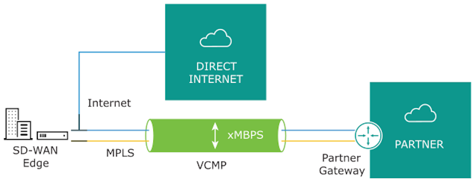
Consider an Edge utilizing a 20 Mbps Internet link and a 20 Mbps MPLS link, paired with a 35 Mbps SD-WAN service from a Service Provider (SP). In this scenario, the SD-WAN service capacity (35 Mbps) remains lower than the aggregate bandwidth of the WAN links (40 Mbps). To ensure that traffic toward the Partner Gateway does not exceed 35 Mbps, the Service Provider places a Tunnel Shaper on the DMPO tunnel.
Configure Rate-Limit Tunnel Traffic
The Operator must activate the Rate-Limit Tunnel Traffic feature before the system allows any edits. To gain access to this feature, contact the Operator for more information.
- Go to from the navigation panel.
- Select the link of the appropriate configuration Profile.
- Select the Business Policy tab and go to Additional Settings.
- In the SD-WAN Overlay Rate Limit area, check the Rate-Limit Tunnel Traffic check box.
- Select either the Percent or Rate (Mbps) radial buttons. By default, None is selected.
- In the Limit text box, type in a numerical limit to the Tunnel Traffic.
- Select Save Changes.
