
Site Configurations Overview
Data center topologies include Hub and VeloCloud branch configurations, which the administrator builds using both MPLS and Internet connections. These topologies also include Legacy branch configurations (sites without an Edge). In these scenarios, the administrator modifies the hub and branch configurations to account for the presence of these legacy branches.
The diagram below illustrates a sample topology featuring two data center Hubs and various branch configurations interconnected via MPLS and the Internet. The system uses this example to describe the specific tasks required for data center and branch configurations.
This section assumes users understand the concepts and configuration details presented earlier in this documentation. The following content focuses on configuring the Networks, Profile Device Settings, and Edge configurations necessary for each topology.
This section also includes additional configuration steps for traffic redirection, routing control (such as for backhaul and VPNs), and Edge failover.
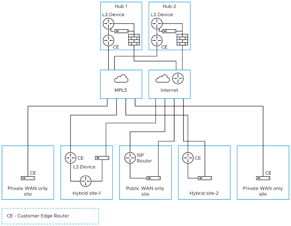
This section focuses on the configurations for topologies that include various data center and branch locations. It explains the Network, Profile/Edge Device Settings, and Profile/Edge Business Policies necessary to complete these setups.
The documentation does not describe certain ancillary configuration steps—such as Network Services, Device Wi-Fi Radio, Authentication, SNMP, and Netflow settings—even though a complete deployment may require them.
Data Center Configurations
An Edge in a data center acts as a Hub to direct traffic to and from branches. The Edge manages both MPLS and Internet traffic, and the administrator can set up the Hub in either a one-arm or two-arm configuration. Additionally, the system can utilize a data center as a backup.
To ensure the data center Hubs handle the specific number of tunnels, flows, and traffic loads from branches, the administrator must perform thorough capacity planning. This planning includes selecting the appropriate Edge model. For more information, consult the Arista Support or Solution Architect team.
The following table describes the various designs with different options for inserting an Edge into the topology:
| Option | Description |
|---|---|
| Hub 1 | Data Center or regional Hub site with Edge deployed in two-arm topology. |
| Hub 2 | Data Center or regional Hub site with Edge deployed in one-arm topology (same interface carries multiple WAN links). |
| Private WAN link(s) only Site | Classic MPLS sites. |
| Hybrid Site-1 | The administrator deploys the Edge off-path. The Edge creates overlay across both MPLS and Internet paths, while the network first diverts traffic to the Edge. |
| Hybrid Site-2 | The administrator deploys the Edge in-path as the default gateway. The Edge always serves as the default gateway. While this topology simplifies the design, it makes the Edge a single point of failure and may require the administrator to implement High Availability (HA). |
| Public WAN link(s) only Site | Dual-Internet site (one of the links is behind a NAT router). |
Configure Branch and Hub
- Configure and activate Hub 1.
- Configure and activate the Hybrid Site-1.
- Enable branch-to-Hub tunnel (Hybrid Site-1 to Hub 1)
- Configure and activate Public WAN only Site
- Configure and activate Hub 2
- Configure and activate Hybrid Site-2
The following sections discuss the steps in more detail.
This step helps users understand the typical workflow bringing up Edge at the hub location. The Edge deploys with two interfaces, one interface for each WAN link.
Users will use the Virtual Edge as a hub. Following is an example of the wiring and IP address information.
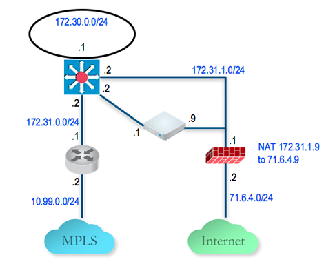
Activating the Virtual Edge in a Default Profile
- Log in to the Orchestrator.
- The default VPN profile allows the activation of the Edge 500.
Activating Hub 1 Edge
- Go to and add a new Edge. Specify the correct model and the profile. In this example, use the Quick Start VPN Profile.
- Go to the hub Edge (DC1-VCE) and follow the normal activation process. If users have the email feature set up, users will receive an activation email at that email address. Otherwise, users can go to the Device Setting page to get the activation URL.
- Copy the Activation URL and paste that to the browser on the PC connected to the Edge or just select on the Activation URL from the PC browser.
- Select Activate.
- Now the DC1-VCE data center hub should be up. Go to. Select Edge Overview. The public WAN link capacity is detected along with the correct public IP
71.6.4.9and ISP. - Go to and select DC1-VCE. Go to the Device tab and scroll down to the Interface Settings. Users see that the registration process notifies the Orchestrator of the static WAN IP address and gateway configured through the local UI. The configuration on the VeloCloud updates accordingly.
- Navigate to the WAN Settings section. The Link Type should be automatically identified as Public Wired.
Configure the Private WAN Link on Hub 1 Edge
Configure Static Route to LAN Network Behind L3 Switch
Configure and Activate Hybrid Site-1
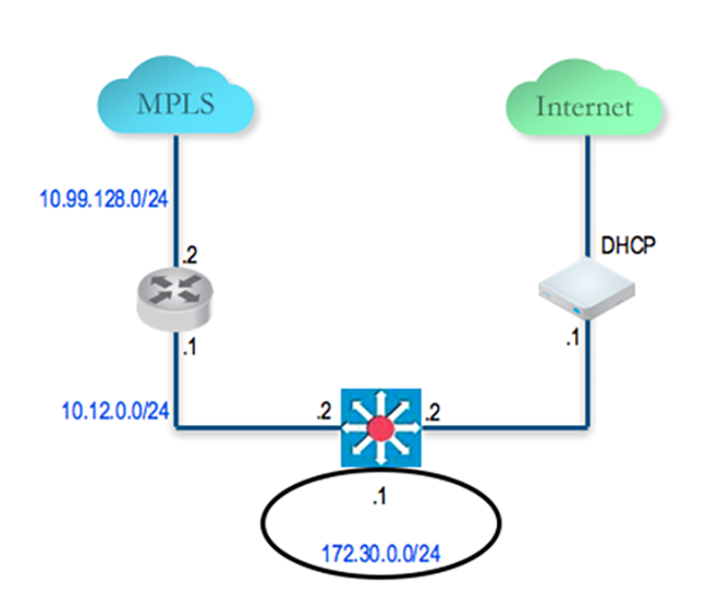
Configure the Private WAN Link on the Hybrid Site-1 Edge
- Go to, select the Hybrid Site-1-VCE and go to the Device tab and navigate to the Interface Settings section. Configure static IP on GE3 as
10.12.1.1/24and the default gateway of10.12.1.2. Under WAN Overlay, select User Defined Overlay. This allows users to define a WAN link manually. - Under WAN Settings, select Add User Defined WAN Overlay.
- Define the WAN overlay for the MPLS path. Select the Link Type as Private. Specify the next-hop IP (
10.12.1.2) of the WAN link in the IP Address field. Choose the GE3 as the Interface. Select Advanced. Tip: Since the hub has already been set up, set it auto-discover the bandwidth. This branch runs a bandwidth test with the hub to discover the link bandwidth. - Set the Bandwidth Measurement to Measure Bandwidth. This causes the branch Edge to run a bandwidth test with the hub Edge in the same manner as the Gateway.
- Validate that the WAN link is configured and save the changes.
Configure Static Route to LAN Network Behind L3 Switch
Add a static route to 192.168.128.0/24 through the L3 switch. Users need to specify the Interface GE3. Make sure users enable the Advertise so the other Edges learn about this subnet behind L3 switch.
Enable Branch to Hub Tunnel (Hybrid Site-1 to Hub 1)
Enable Cloud VPN and Edge to Hub Tunnel
Configure and Activate Public WAN only Site
Configure and Activate Hub 2
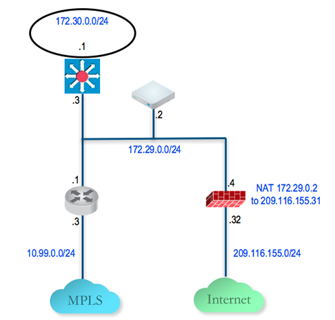
Configure the Hub 2 Edge to Reach the Internet
- Configure the Hub Edge to reach the Internet by configuring the first WAN interface, GE2.
Figure 5. WAN Interface Configuration 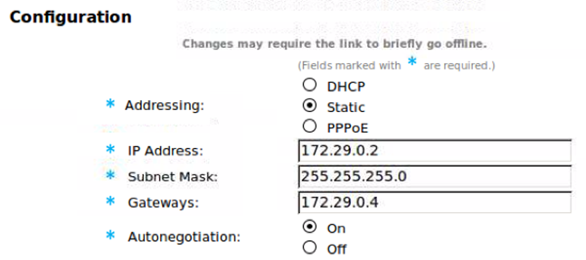
Add the Hub 2 Edge to the Orchestrator and Activate
- On the Orchestrator, go to, select New Edge to add a new Edge.
- Go to , select the Edge that users just created, then navigate to the Device tab to configure the same Interface and IP configured in the previous step. Because the configuration deploys the Edge in one-arm mode (same physical interface, but multiple over tunnels created from this interface, it is important to specify the WAN Overlay as User-Defined.
- At this point, users need to create the overlay. Under WAN Settings, select Add User Defined WAN Overlay.
- Create an overlay across the public link. In the example, use the next-hop IP of
172.29.0.4to reach the Internet through the firewall. The firewall has a configuration to NAT the traffic to209.116.155.31. - Add the second overlay across the private network. In this example, specify the next-hop router
172.29.0.1and also specify the bandwidth since this is the MPLS leg and DC2-VCE is a hub. Add a static route to the LAN side subnet,172.30.128.0/24through GE2. - Activate the Edge. After the activation is successful, return to the Device tab under the edge level configuration. Note, it populates the Public IP field now. Users should see the links in the , under the Overview tab.
Add the Hub 2 Edge to the Hub List in the Branch VPN Profile
- Go to and select the profile Quick Start VPN.
- Go to the Device tab and add this new Edge to a list of hubs.
Configure and Activate Hybrid Site-2
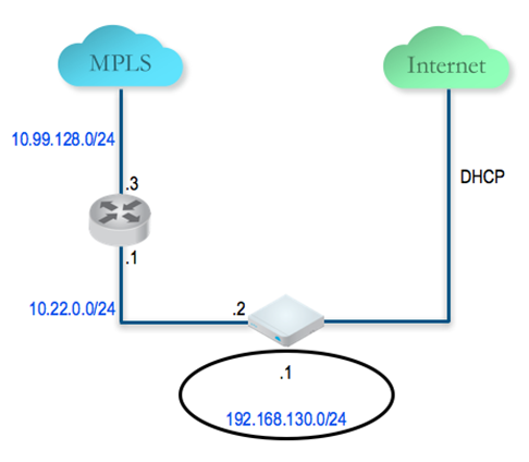
Connect a PC to the Edge LAN or Wi-Fi and use the browser to point to http://192.168.2.1.
For additional information on activation of Edges, see Activate Edges.