Configure High Availability on an Edge
This section discusses the high availability deployments and configurations that an Edge supports.
How High Availability Works
The High Availability solution ensures uninterrupted traffic flow in the event of failures. The Edge functions as the data plane component deployed at the end-user branch location. Edges configured in High Availability (HA) mode are mirror images of each other and appear on the Orchestrator as a single Edge.
A High Availability (HA) configuration utilizes a pair of Edges in Active and Standby roles at the branch site. The Orchestrator automatically mirrors all configurations across both these Edges. Active and Standby Edges exchange heartbeats across a failover link established over the wired WAN connection. If the Standby Edge loses connectivity with the Active Edge for a defined period, the Standby Edge assumes the identity of the Active Edge and takes over the traffic load. The failover has minimal impact on the traffic flow.
The Orchestrator communicates only with the Active Edge. The Orchestrator synchronizes all configuration changes from the Active Edge to the Standby Edge via the failover link.
Limitations
On software versions prior to 5.2.3, a customer cannot perform a Simple Network Management Protocol (SNMP) walk for the attributes ifHCInOctets and ifHCOutOctets on the Standby Edge in a High-Availability Edge pair.This topic contains the following section:Failure Scenarios
Failure Scenarios
- WAN link failure - The failure of a WAN link on the Active Edge triggers an automatic failover action. The Orchestrator generates the “High Availability Going Active” event. Consequently, a WAN link on the Standby Edge assumes the Active role to compensate for the failed interface on the peer Edge.
- LAN link failure - The failure of a LAN link on the Active Edge triggers an automatic failover action. The Orchestrator generates the “High Availability Going Active” event. Consequently, a LAN link on the Standby Edge assumes the Active role to compensate for the failed interface on the peer Edge.
- Edge functions not responding, or Edge crash / reboot / unresponsive - When the Active Edge crashes, reboots, or is unresponsive, the Standby Edge does not receive any heartbeat messages. The Orchestrator generates the “High Availability Going Active” event and the Standby Edge assumes the Active role.
- Service Restart - Configuration changes that trigger a service restart cause a failover. The service restart occurs after the Orchestrator applies the configuration changes to both the Standby Edge and the Active Edge. For a list of changes that cause a service restart, see Arista VeloCloud SD-WAN Edge Configuration Changes that Trigger an Edge Service Restart.
- Non-directly connected HA pairs failure - In High Availability (HA) setups, having Active and Standby Edges in different, non-directly connected locations can cause Active/Active panics and HA instability due to missed keepalive signals.
Missing heartbeats, especially over long distances with multiple hops, can cause problems. If communication fails or the HA link disconnects, missing just 700 milliseconds of heartbeats can cause both Edges to think they are active, leading them to respond to Address Resolution Protocol (ARP) requests and potentially triggering a broadcast storm.
VeloCloud SD-WAN does not support non-directly connected HA setups. Latency between sites should be under 100 milliseconds, but distance and equipment can affect this. To avoid issues, use directly connected pairs for HA setups.Note: VeloCloud SD-WAN does not recommend using a Layer 2 switch for the HA link between the two Edge devices.
High Availability Deployment Models
- Standard HA: In this model, the Active and Standby Edges have the same configurations and symmetric connections, meaning both Edges connect to the same WAN links. All ports on the Active Edge are open for receiving and sending traffic. At the same time, the system blocks all ports on the Standby Edge except for GE1. The system utilizes the GE1 interface to exchange heartbeats between the Active and Standby Edges. See Standard HA.
- Enhanced HA: In this model, the Active and Standby Edges maintain identical configurations while utilizing asymmetric connections; specifically, each Edge connects to independent WAN links. The system utilizes the GE1 interface to exchange heartbeats between the Active and Standby Edges. The Active Edge can leverage the WAN link connected to the Standby Edge to send or receive traffic. It forwards the traffic through the GE1 interface to the Standby Edge, which in turn sends the traffic through the WAN link. See Enhanced HA.
- Mixed-mode HA: This model combines both Standard and Enhanced HA deployments on the same site. In this model, the Active and Standby Edges have the same configurations. The connections can be both symmetric and asymmetric. See Mixed-Mode HA.
The following Edge platforms support High Availability (HA) options: 510, 510N, 520, 520v, 540, 610, 610N, 620, 620N, 640, 640N, 680, 680N, 840, 2000, 3400, 3800, 3810, 7x0, 4100, 5100 and any Virtual Edge.
- "HA Wi-Fi capability mismatch identified, disabled Wi-Fi." - The system identifies an Edge Wi-Fi mismatch and automatically deactivates Wi-Fi on the capable Edge.
- "HA Wi-Fi capability mismatch no longer seen, reverted Wi-Fi." - Once the system detects that both Edges share the same Wi-Fi type, it automatically restores Wi-Fi functionality on the previously deactivated Edge.
Standard HA
This section describes Standard High Availability (HA).
Topology Overview for Standard HA
The following figure shows a conceptual overview of Standard HA.
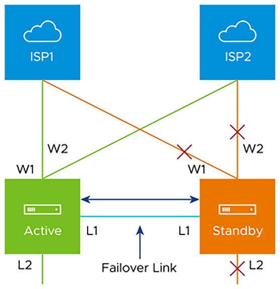
The Edges, one Active and one Standby, are connected by L1 ports to establish a failover link. The Standby Edge blocks all ports except the L1 port for the failover link.
Prerequisites for Standard HA
- Configure the LAN side switches with STP and ensure they are STP-capable.
- Connect Edge LAN and WAN ports to different Layer 2 (L2) switches. If it is necessary to connect the ports to the same switch, then the LAN and WAN ports must be isolated from each other.
- The two Edges must have mirrored physical WAN and LAN connections.
Deployment Types for Standard HA
- Deployment Type 1: High Availability (HA) using L2 switches
- Deployment Type 2: High Availability (HA) using L2 and L3 switches
Deployment Type 1: HA using L2 Switches
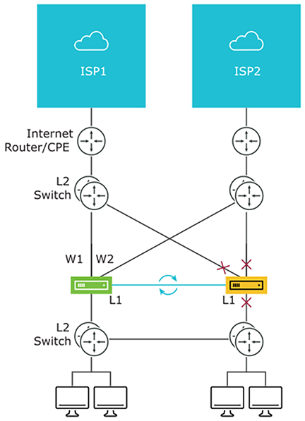
The following sections describe these two deployment types. The following figure shows the network connections using only L2 switches.
Considerations for HA Deployment using L2 switches
- Connect the same ISP link to the same port on both Edges.
- Use the L2 switch to make the same ISP link available to both Edges.
- The Standby Edge does not interfere with any traffic by blocking all its ports except the failover link (L1 port).
- The system synchronizes the Session information between the Active and Standby Edges through the failover link.
- If the Active Edge detects a loss of a LAN link, it will also failover to the Standby if it has an Active LAN link.
Deployment Type 2: HA using L2 and L3 Switches
The following figure shows the network connections using L2 and L3 switches
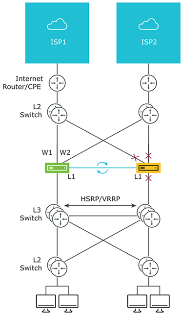
The Edge utilizes WAN connections (W1 and W2) to connect to the L2 switches, providing a WAN connection to ISP1 and ISP2, respectively. The Edge uses L1 connections to establish a failover link for HA support. The Edge connects to L2 switches, which in turn connect several end-user devices.
Considerations for HA Deployment using L2 and L3 switches
- It is mandatory to configure HSRP/VRRP on the L3 switch pair.
- The Edge's static route points to the L3 switches’ HSRP VIP as the next hop to reach the end stations behind the L2 switches.
- Connect the same ISP link to the same port on both Edges. The L2 switch must make the same ISP link available to both Edges.
- The Standby Edge does not interfere with any traffic by blocking all of its ports except the failover link (L1 port).
- The failover link synchronizes session information between the Active and Standby Edges.
- The HA pair also does a failover from Active to Standby on detecting the L1 loss of LAN / WAN links.
- If Active and Standby have the same number of LAN links that are up, but Standby has more WAN links up, then a switchover to Standby will occur.
- If the Standby Edge has more LAN links up and has at least one WAN link up, then a failover to the Standby will occur. In this situation, the system assumes that the Standby Edge has more users on the LAN side than the Active Edge, and that the Standby will allow more LAN side users to connect to the WAN, given that there is some WAN connectivity available.
Enhanced HA
This section discusses Enhanced high Availability (HA). The Enhanced HA eliminates the need for L2 Switches on WAN side of the Edges. For LAN side settings, refer to the Standard HA documentation. The Active Edge chooses this option when it detects different WAN links on the Standby Edge than those connected to itself.
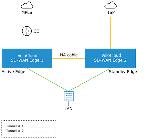
The Active and Standby Edges use an HA link to establish a failover connection. The Active Edge then establishes overlay tunnels on both WAN links (its own and those of the Standby Edge) via that HA link.
To leverage the WAN link connected to the Standby Edge, the Active Edge establishes an overlay tunnel through the HA link. The Active Edge forwards LAN-side traffic to the Internet through the HA link. The business policy for the branch defines the traffic distribution across the overlay tunnels.
Enhanced HA Support for LTE Interface
Long-Term Evolution (LTE) is a standard for wireless broadband communication for mobile devices and data terminals, based on the GSM/EDGE and UMTS/HSPA technologies. It increases capacity and speed by utilizing a different radio interface in conjunction with core network improvements. VeloCloud SD-WAN supports LTE in 510 and 610 Edge models, which have two SIM slots.
Starting with the 4.2 release, the system counts the LTE link/CELL interface in the HA election. Internally, a lesser weight is assigned to CELL links than to wired links. Depending on the number of wired links connected to each Edge in the eHA pair, the Edge with the LTE link can be either the Active or Standby Edge. Here are some use cases for eHA with LTE interface.
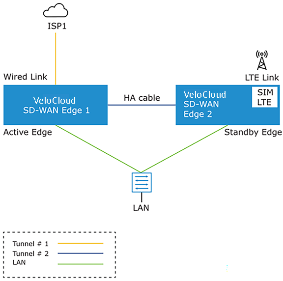
The figure illustrates the topology of Enhanced HA support for LTE Interface on a Standby Edge. In this example, an HA cable connects the Active Edge (Edge 1) and the Standby Edge (Edge 2) to establish a failover link. The system prefers the Edge with the wired WAN link as the Active Edge.. The Standby Edge utilizes an LTE link for establishing the tunnel. The Standby Edge can use its LTE link in an active, backup, or hot-standby role, depending on the configuration. The Active Edge establishes overlay tunnels on WAN link connected to itself and the LTE link on the Standby Edge through the HA link. If an Active Edge fails, the Standby Edge will continue to forward the LAN-side traffic through the LTE link.
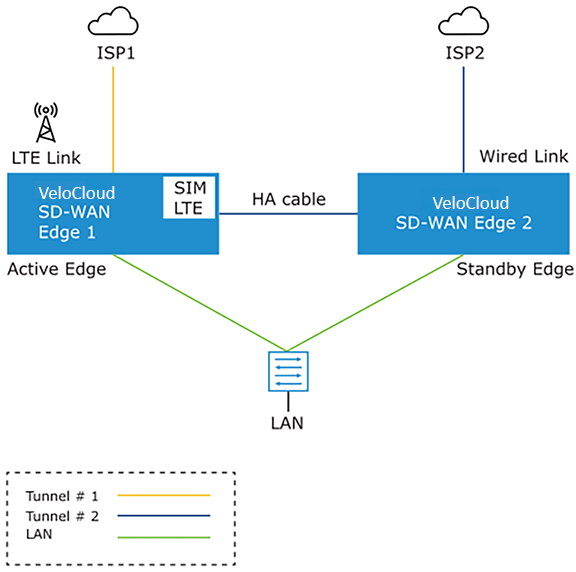
The figure illustrates the topology of Enhanced HA support for LTE Interface on an Active Edge. In this example, Edge 1, with one wired link and one LTE link, acts as an Active Edge, and Edge 2, with one wired link, acts as a Standby Edge. If the wired WAN link on the Active Edge fails, the Standby Edge will take over as the Active Edge, and it will use the LTE link in eHA mode.
Supported Topologies
- 510 - 510 LTE HA pair
- 610 - 610 LTE HA pair
- 510 LTE - 510 LTE HA pair
- 610 LTE - 610 LTE HA pair
- 710 W - 710 5G HA pair
- 710 5G - 710 5G HA pair
Limitations
- LTE Dual SIM Single Standby (DSSS) is not supported with eHA LTE.
- USB modems on Standby Edge in eHA mode is not supported.
Troubleshooting Enhanced HA support for LTE
Users can troubleshoot the Enhanced HA support for LTE Interface feature, by running the following remote diagnostic tests on an Edge:
- LTE Modem Information: Run this test on a selected Edge interface to collect diagnostic details such as Modem information, Connection information, Location information, Signal information, and Status information for the internal LTE modem.
Figure 7. LTE Modem Information 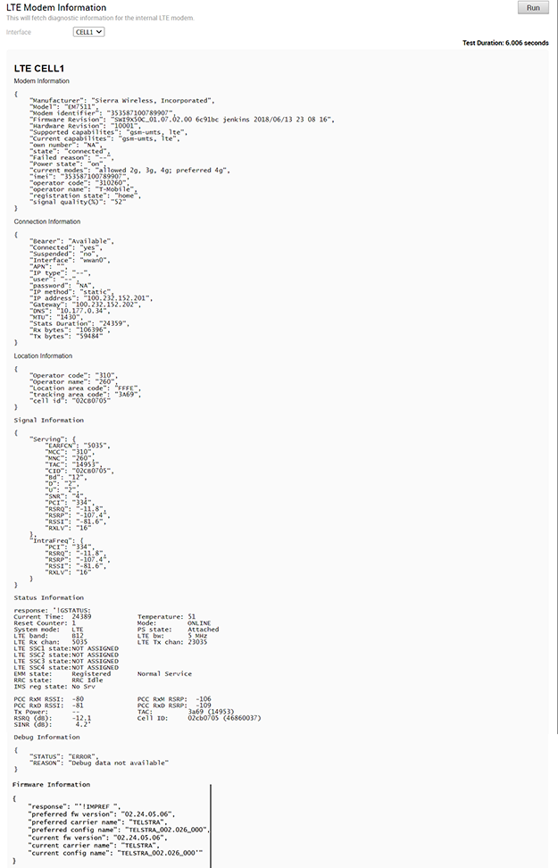
- Reset USB Modem: Run this test on a selected Edge interface to reset a non-working USB modem connected to the given interface. Note that only certain USB modems support this type of remote reset.
Figure 8. Reset USB Modem 
Mixed-Mode HA
The Mixed-mode HA deployment model is a combination of Standard HA and Enhanced HA deployments. In this deployment model users can have both shared interfaces and individual interfaces.
Let us consider a scenario where the private network is unable to communicate with the Orchestrator or the Controller.
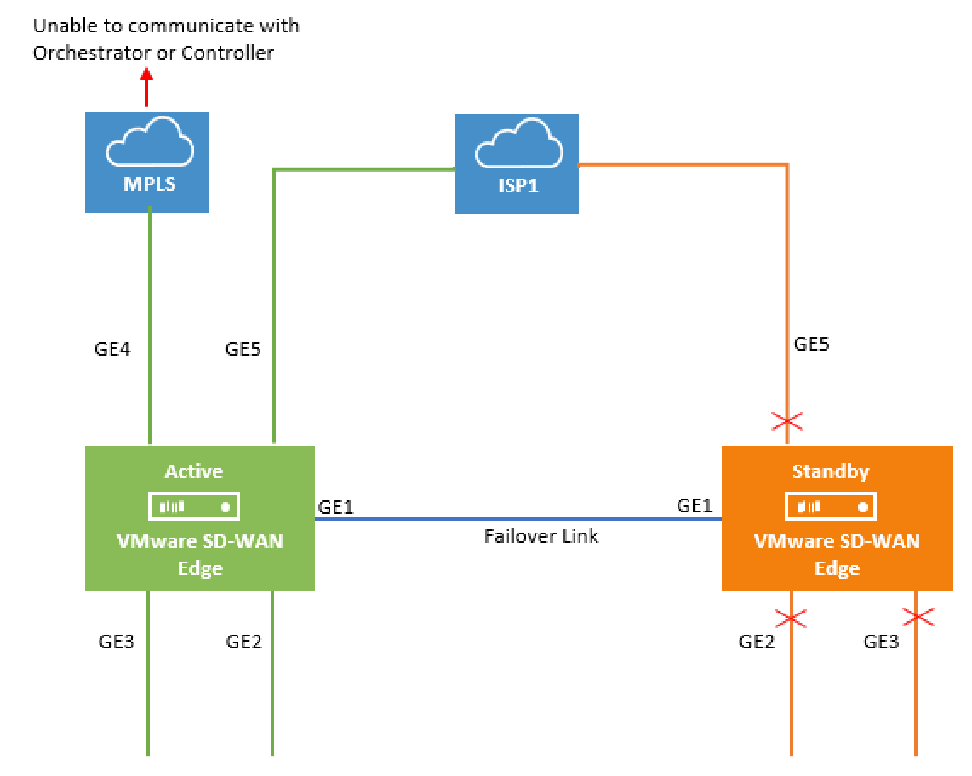
In this topology, the Active and Standby Edges exchange heartbeat messages, synchronize configuration updates, and other information over the GE1 interface. Both Edges have mirrored LAN and WAN connections over the GE2, GE3, and GE5 interfaces, which is similar to the Standard HA deployment model. However, the Active Edge is connected to the private network using the GE4 WAN link. This configuration is similar to the Enhanced HA deployment model. The Active Edge maintains all ports open to send and receive traffic. The Standby Edge blocks all ports except GE1.
When the MPLS network is unable to communicate with the Orchestrator or the Controller, the site would still have connectivity to the Orchestrator or the Gateway. It would be able to build public overlays.
Now, let us consider a scenario when both private and public networks are unable to communicate with the Orchestrator or Controller.
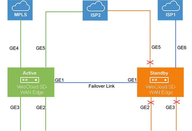
In this topology, ISP1 connects only to the Standby Edge via the GE6 WAN link, while ISP2 connects to both the Active and Standby Edges via the GE5 WAN link. The Active Edge keeps all its ports open to send and receive traffic. The Active Edge utilizes the GE6 WAN link to route traffic to the public network, ISP1, via GE1.
Split-Brain Condition
When the HA link is disconnected or when the Active and Standby Edges fail to communicate with each other, both Edges assume the Active role. As a result, both Edges start responding to ARP requests on their LAN interfaces. LAN traffic flows to both Edges in this scenario, potentially creating a broadcast storm.
Typically, LAN switches connected to the HA Edge pair LAN ports run the Spanning Tree Protocol to prevent loops, which trigger broadcast storms in the network. In such a condition, the switch would block traffic to one or both Edges. However, doing so would cause a total loss of traffic through the Edge pair.
Split-Brain Detection and Prevention
This section discusses the mechanisms used to detect and prevent a split-brain state in an Edge deployment using a high availability topology.
There are two mechanisms for detecting and preventing a split-brain condition in a high-availability deployment (where both HA Edges become Active).
The first mechanism involves sending Layer 2 broadcast heartbeats between the two HA Edges when the HA heartbeat link between the devices is lost. A Layer 2 broadcast (EtherType 0x9999) heartbeat is sent from the Active Edge on all its WAN interfaces in an effort to find the Standby Edge in that broadcast network. When the Standby Edge receives this packet, it interprets the packet as an indication to maintain its current Standby state. A Legacy High Availability deployment uses this mechanism, where both HA Edges have their WAN ports connected to the same Layer 2 Switch.
The second mechanism used to detect and prevent split-brain conditions leverages the Primary Gateway used by the HA Edges. This mechanism is the sole means of detecting and preventing split-brain in an Enhanced High Availability deployment, as this topology does not connect both HA Edges to an upstream Layer 2 switch.
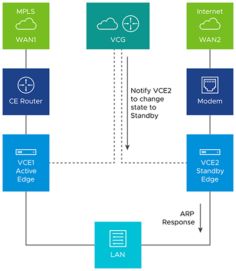
The Gateway has a pre-existing connection to the Active Edge (VCE1). In a split-brain condition, the Standby Edge (VCE2) changes state to Active and tries to establish a tunnel with the Gateway (VCG). The Gateway will send a response back to the Standby Edge (VCE2), instructing it to transition to the Standby state, and will not establish the tunnel. The Gateway keeps its tunnels only with the Active Edge. The sequence of events is as follows.
As soon as the HA link fails, the VCE2 moves to the Active state and enables the LAN/WAN ports, and tries to establish tunnels with the Primary Gateway. If the VCE1 still has tunnels, the Primary Gateway instructs the VCE2 to revert to the Standby state, and thus the VCE2 blocks its LAN ports. Only the LAN interfaces remain blocked (as long as the HA cable is down). As illustrated in the following figure, the Gateway signals VCE2 to enter the Standby state, which logically prevents the split-brain scenario from occurring.
- The normal failover from Active to Standby in a split-brain scenario is not the same as the normal failover. It could take a few extra milliseconds/seconds to converge.
- When configuring WAN interface settings for an Edge, if a user selects PPPoE from the Addressing Type field, the Edge cannot send heartbeat packets by broadcast from a WAN interface so configured.
Support for BGP over HA Link
In a High Availability topology, the Active Edge exchanges BGP routes with its peer over the HA link. In an Enhanced HA deployment, BGP on the Active Edge establishes a neighborship with a peer connected to the Standby Edge’s WAN link.
Beginning with SD-WAN Release 5.1.0 and onwards, a site deployed in High Availability with BGP configured automatically synchronizes local routes between the Active and Standby Edges. It uses these routes for forwarding on the Active Edge while also ensuring that the route table is immediately available after an HA failover. This improves failover times as the routes are already available on the Standby Edge when the system promotes it to Active.
High Availability Graceful Switchover with BGP Graceful Restart
- Deploy a site with a High Availability topology. This site can be either Active/Standby or VRRP with a third-party router. BGP Graceful Restart does not have any effect on a standalone Edge site, only on sites using HA.
- The customer enterprise must configure BGP as the routing protocol.
BGP Graceful Restart with Graceful Switchover ensures faster Edge restarts and HA failovers by having neighboring BGP devices participate in the restart, ensuring that no route changes occur in the network during the restart. Without BGP Graceful Restart, the peer Edge deletes all routes after the TCP session between BGP peers terminates. The system must rebuild these routes after the Edge restarts or undergoes an HA failover. BGP Graceful Restart ensures that peer Edges retain routes while the system establishes a new session within a configurable restart timer.
Limitations/Known Behaviors:
BGP Graceful Failover and HA Graceful Switchover are segment-agnostic. When activated on one segment (for example, the Global Segment), the system applies these settings to all other segments on a customer site. This means the Edge synchronizes routes across other segments and holds stale routes during an HA failover.
Configuring BGP Graceful Restart
Configuring BGP Graceful Restart requires two steps: one in the BGP configuration section and another in the High Availability configuration section. The steps are:
- Activate BGP Graceful Restart on .
- Scroll down and then expand the BGP section for the Edge or Profile.
Figure 12. Routing and NAT 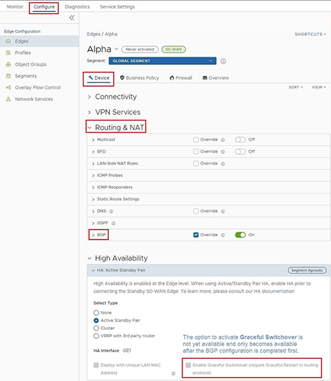
- In the BGP section, select the Graceful Restart checkbox.
Figure 13. Graceful Restart 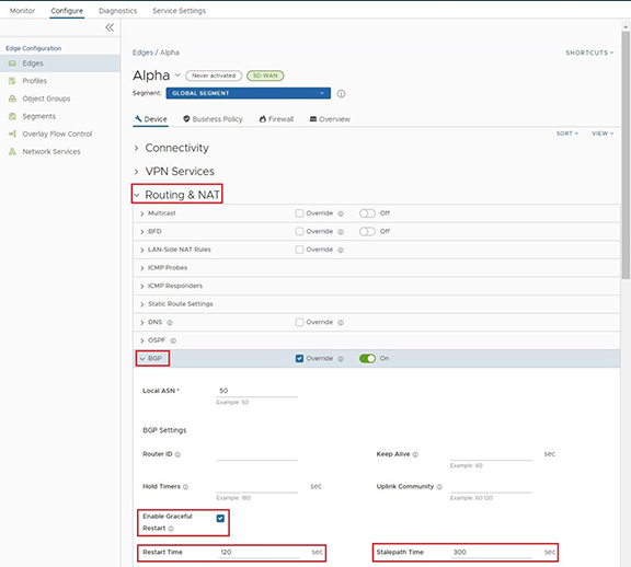
- Scroll down and then expand the BGP section for the Edge or Profile.
- Activate Graceful Switchover on .
- From the BGP section, scroll down to the High Availability section.
Figure 14. High Availability 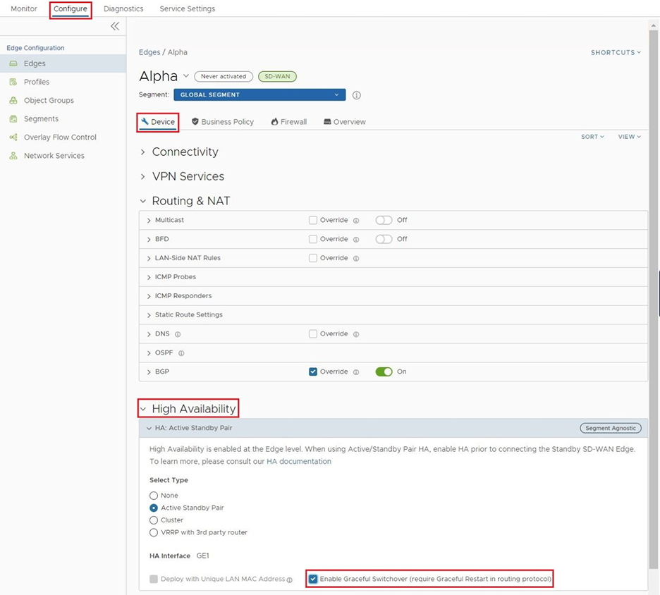 Note: Activating BGP Graceful Restart enables the Graceful Switchover checkbox.
- From the BGP section, scroll down to the High Availability section.
- Select Save Changes.
Selection Criteria to Determine Active and Standby Status
- Check for the Edge that has a higher number (L2 and L3) LAN interfaces. The system chooses the Edge with the higher number of LAN interfaces as the Active one. Note that the system does not count the HA link interface as a LAN interface.
- If both Edges have the same number of LAN interfaces, the system chooses the Edge with the higher number of WAN interfaces as the Active one.
Note: There is no preemption if the two Edges have the same number of LAN and WAN interfaces.
- Additional Support Matrix:
- Static/DHCP/PPPoE links are supported.
- Multiple WAN links each tagged with a separate VLAN ID on a single interface (e.g. Sub-Interfaces) are supported.
- Arista does not recommend USB modems on HA. The interface will not be used when present in the Standby Edge.
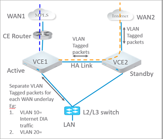
VLAN-tagged Traffic over HA Link
- Internet traffic from ISP2 is VLAN-tagged.
- Customer will have separate VLANs for Enterprise traffic versus DIA traffic.
- The WAN link on the Standby has sub-interfaces to carry Internet traffic.
- Multi segments.
Configure High Availability
To configure High Availability, first configure the Active and Standby Edges.
This topic contains the following sections:
Deploying High Availability on ESXi
Users can deploy the VeloCloud SD-WAN HA on ESXi using the supported topologies. While deploying HA on ESXi, consider the following limitations:
ESXi vSwitch Caveats
- The vSwitch directly connected to a virtual SD-WAN VNF does not propagate upstream failures. For example, if a physical adapter fails, the Edges will still see the link as up and will not fail over.
- vSwitches do not allow the configuration of specific VLANs on a port group. If more than one VLAN is required, then VLAN 4095 must be configured. This configuration allows all VLANs on the port group.
Note: This is not applicable to br-HA Link, which does not require VLANs.
- The virtual Edge, when working as HA, changes its original assigned MAC Address. In order to allow the virtual Edge to receive frames with a MAC Address that is different from the one originally assigned, set the MAC address changes option on the virtual switch to Accept.
- To allow the virtual Edge to receive traffic in the br-HA Link with multiple destination MAC Addresses, change the security settings on the port group or virtual switch to allow it to run in Promiscuous mode.
Limitation of VeloCloud SD-WAN High Availability: There is no generic way of failure detection that will work on all the hardware, virtual, and uCPE platforms.
Enable the Loss of Signal (LoS) detection to determine the HA Failover. For additionalinformation, refer to HA LoS Detection on Routed Interfaces.
- The following illustrated legacy HA topology uses a single physical adapter for WAN uplinks and one routed or truncated LAN.
Figure 16. Topology 1: Legacy HA with WAN links 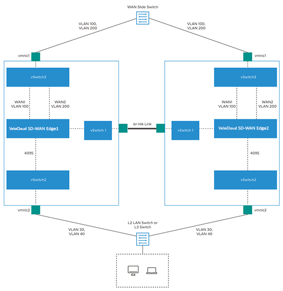
- The following topology shows Enhanced HA with three WAN links.
Figure 17. Topology 2: Enhanced HA with WAN Links 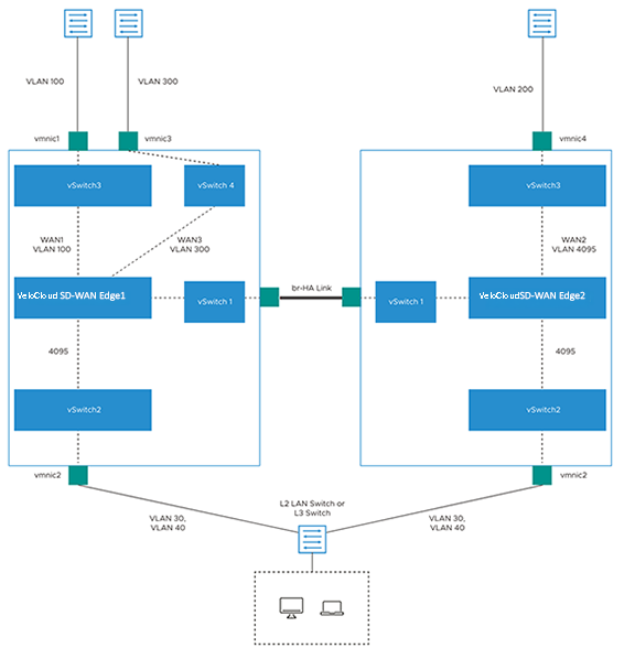
- The following image shows Enhanced HA with subinterfaces on the WAN interfaces with VLAN ID as 4095 on port group.
Figure 18. Topology 3: Enhanced HA with Subinterfaces 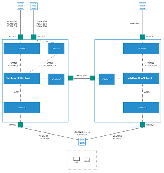
HA LoS Detection on Routed Interfaces
For an HA-enabled Edge, the system detects the number of connected LAN and WAN interfaces and uses this count to decide whether to trigger an HA failover.
The ESXi deployment uplinks the virtual Edge's LAN and WAN interfaces through either a single physical NIC or a group of physical NICs. If one of the physical NICs is down, the Interface count computed by HA does not differ from that of the Edge vNICs. The vSwitch connections remain intact, preventing the HA Failover.
By enabling LoS detection on a routed Interface, it is possible to determine loss of Signal and Failover. The LoS detection can be done based on ARP monitoring of the next hop for routed Interfaces. The LoS detection is performed only on Active Edges and only for Interfaces that are up.
If an Interface is physically up but LoS is detected, then the Interface is considered down, and the relevant action, that is HA Failover, is taken based on the Active and Standby Interface count. LoS detection is done only on the parent Interface and not on its sub-interfaces, as the underlying physical link is common for both. The system considers the Interface as down with LoS when it misses three consecutive ARP responses within the configured probe interval.
- LoS detection works only for routed Interfaces, as the Edge does not know the next hop in a switched Interface. PPPoE Interfaces and statically configured Interfaces without a default Gateway do not support LoS detection.
- Interfaces that are up only on the Standby Edge do not support LoS detection.
- The Standby Edge does not perform LOS probing on its interfaces. Hence, the system cannot detect any Interface connectivity change on the Standby Edge.
- Previous HA deployment blocks all Interfaces on the Standby Edge. As LoS monitoring uses ARP probing to detect the liveliness of the link, the system cannot ascertain the connectivity state of links present on the Standby Edge because blocked Interfaces and ARP packets cannot pass through.
Enable LoS Detection
- Configure the other settings as required and select Update.
Figure 19. HA LoS Detection 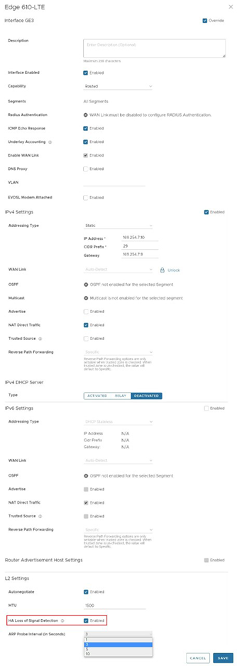
Monitor Events for LoS Detection
In the Enterprise portal, navigate to .
To view the events related to LoS Detection on a routed Interface of a virtual Edge, use the filter option. Click the drop-down arrow next to the Search option and choose to filter by either the Event or Message column.
- LoS detected on peer's Interface Interface name.
- LoS no longer seen on Interface Interface name.
Unique MAC LAN and WAN Address
Virtual High Availability environments utilizing VNF Service Chaining require unique MAC addresses for the LAN and WAN ports on both the Active and Standby Edges.
Instead of generating a common or shared virtual MAC address when in HA, this feature uses the physical MAC address for hardware Edges and the assigned MAC address for virtual Edges.
Arista recommends this feature for virtual HA deployments, especially when the vSwitch does not support MAC Learning.
Configure a Unique LAN and WAN MAC Address for HA Edges
By default, High Availability uses a common virtual MAC address to support seamless failover between devices. For using a unique MAC address in certain virtual environments, instead of generating a common or shared virtual MAC address, select both Deploy with Unique LAN MAC Address and Deploy with Unique WAN MAC Address checkboxes. By default, the system deactivates these checkboxes. Both options use the physical MAC address for hardware Edges and the assigned MAC address for virtual Edges. When selected, the LAN, Routed LAN, and WAN links all use physical MAC addresses.
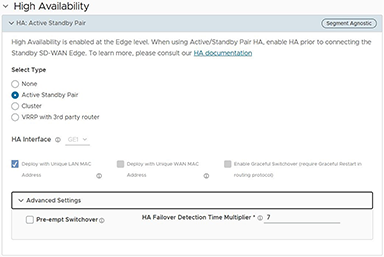
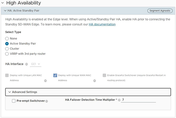
- Disconnect the Standby Edge's WAN and LAN links, so that only the HA link to the Active Edge remains. If it is a Virtual Edge, deactivate the WAN and LAN vNICs, leaving only the HA interface NIC active.
- In the High Availability section, select None.
- Select Save Changes at the top of the Device window.
- Enable High Availability again, and then select or clear the Deploy with Unique LAN MAC checkbox to activate or deactivate the option.
- After the HA status becomes High Availability Ready on the Orchestrator UI, reconnect the LAN and WAN cables of the Standby Edge. In case of Virtual Edges, re-enable the virtual NICs.
Prerequisites
- The two Edges must be the same model.
Note: Release 5.4.0 and later support the mixing of Wi-Fi capable and Non-Wi-Fi capable Edges in High Availability.
Beginning in 2021, VeloCloud SD-WAN introduced Edge models, which do not include a Wi-Fi module: the Edge models 510N, 610N, 620N, 640N, and 680N. Before Release 5.4.0, the system did not support pairing a Wi-Fi capable Edge with a non-Wi-Fi capable Edge of the same model (e.g., Edge 640 and Edge 640N) for High Availability. Release 5.4.0 supports this combination, allowing customers to deploy Edges of the same model number with different Wi-Fi capabilities.
- Provision only one Edge on the Orchestrator.
- The Standby Edge must not have an existing configuration.
- Avoid using 169.254.2.x for the management interface.
Activate High Availability
- In the SD-WAN service of the Enterprise portal, select .
- Select the Edge from the list and select the Device tab.
- Scroll down to the High Availability section, and then select Active Standby Pair.
Figure 22. High Availability 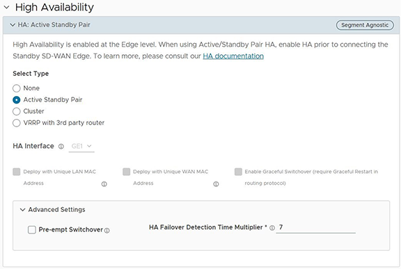
- Select Save Changes at the bottom of the Device window.
- For Edges 520, 520v, and 540: These platforms utilize the LAN1 port for the HA interface but do not support DPDK.
- For Edges 510, 610, 620, 640, 680, 840, 2000, 3400, and 3800: These platforms utilize the GE1 port for the HA interface and support DPDK.
The Orchestrator automatically selects these default HA interfaces for their respective platforms.
Configure a Non-Default High Availability Interface
Beginning with Release 5.2.0, the Orchestrator enables users to configure any LAN interface as the HA interface using the HA Interface option.
Users can select any Edge 1G/10G Ethernet/SFP port without a WAN-Overlay as the HA interface using the HA Interface drop-down menu. For a list of supported SFP modules for use on SD-WAN Edges, see Arista SD-WAN Supported SFP Module List.
Both HA Edges must be upgraded to Release 5.2.0 or later before using a non-default interface for HA traffic. Until both HA Edges are using Release 5.2.0, they must be configured to use the default GE1 as their HA interface. Users can only configure HA Edges to use an interface other than GE1 after they upgrade both HA Edges to Release 5.2.0.
To configure a non-default HA interface, disable the HA for that site or configure it before enabling HA for the site. However, to change the HA Interface on a site where HA is already enabled, first disable HA, then change the HA Interface, and then re-enable HA.
VeloCloud now supports factory images starting with the 5.2.4 MR. If the Edge has a factory image earlier than version 5.2.0, the Edge can automatically upgrade to the 5.2.4 MR image by connecting to a DHCP-enabled Internet connection, contacting the VeloCloud-hosted Maestro server, and downloading the latest applicable factory image. The system upgrades the Edge platforms 610, 610-LTE, 620, 640, 680, 3400, 3800, 3810 to the 5.2.4 MR image by default.
- Connect the Edge to a DHCP-enabled Internet connection.
- Wait a few minutes for the Edge to contact the VeloCloud Maestro server, download the 5.2 MR factory image, and complete the upgrade.
Figure 23. VeloCloud Maestro Server 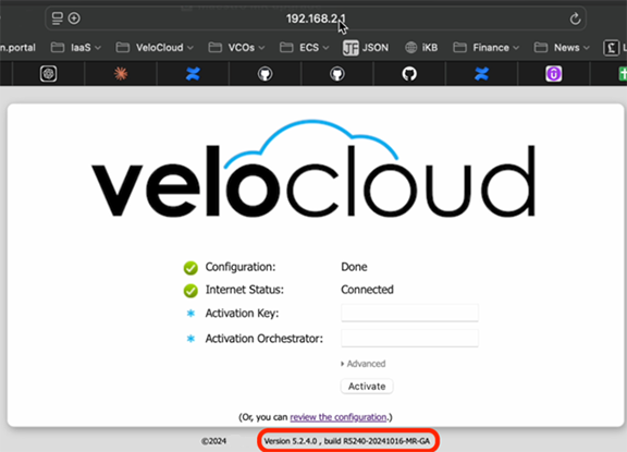
- Connect the HA interface cable on the upgraded Edge and proceed with HA activation. This process is particularly relevant for customers deploying High Availability with non GE1 interface. This is also applicable for RMA devices for the above listed platforms to the 5.2.4 MR image if they have a factory image earlier than version 5.2.0.
- Disable HA.
- Reconfigure the HA Interface to its default value (GE1 or LAN1) on the UI, and relocate the HA Interface cable to the default HA Edge interface.
- Integrate the replacement Edge into the HA topology of the site.
- Re-enable HA and allow the replacement Edge to complete the activation process, assuming the role of the Standby Edge.
- Disable HA.
- Reconfigure the HA Interface to its alternative value on the UI, and relocate the HA Interface cable back to the alternative location on the HA Edges.
- Re-enable HA to finalize the replacement process.
Configure a Unique LAN and WAN MAC Address
By default, High Availability uses a common virtual MAC address to support seamless failover between devices. For using a unique MAC address in certain virtual environments, instead of generating a common or shared virtual MAC address, select both Deploy with Unique LAN MAC Address and Deploy with Unique WAN MAC Address checkboxes. By default, the system deactivates these checkboxes. Both options use the physical MAC address for hardware Edges and the assigned MAC address for virtual Edges. When selected, the LAN, Routed LAN, and WAN links all use physical MAC addresses.
Users can activate or deactivate the Deploy with Unique LAN MAC Address and Deploy with Unique WAN MAC Address checkboxes only when they enable High Availability by choosing Active Standby Pair. Enabling High Availability fixes these options, restricting the users from modifying them.
- Disconnect the Standby Edge's WAN and LAN links, so that only the HA link to the Active Edge remains. If it is a Virtual Edge, deactivate the WAN and LAN vNICs, leaving only the HA interface NIC active.
- In the High Availability section, select None.
- Select Save Changes at the top of the Device window.
- Enable High Availability again, and then select or clear the Deploy with Unique LAN MAC checkbox to activate or deactivate the option.
- After the HA status becomes High Availability Ready on the Orchestrator UI, reconnect the LAN and WAN cables of the Standby Edge. In case of Virtual Edges, re-enable the virtual NICs.
Advanced Settings: HA Failover Detection Time Multiplier
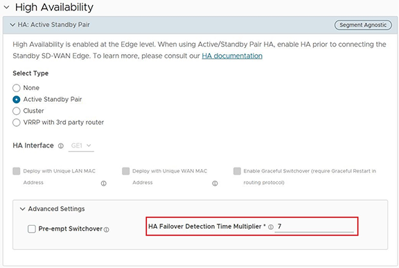
Beginning in Release 5.2.0, users can manually configure the time threshold before the system marks the Active Edge as non-responsive, which triggers a failover to the Standby Edge. On some Edge platforms, an Edge may experience a high amount of traffic that is sufficient to delay sending a heartbeat response to the Standby Edge, indicating that it is still functioning. This delay may exceed the default 700 millisecond threshold and trigger the Standby Edge to become active and resulting in an Active-Active (Split-Brain) state. With this feature, the user can increase the time threshold before the Active Edge is declared down and trigger a failover and prevent a potential split-brain state.
The Advanced Options section provides a field to update this value, allowing users to configure the HA Failover Detection Time Multiplier. The system multiplies this number by 100 milliseconds (ms). This multiplier defaults to 7 (700 ms) and supports a maximum setting of 70 (7000 ms).
Advanced Settings: Pre-empt HA Switchover
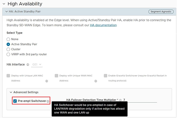
The High Availability (HA) process chooses the Active Edge device based on which Edge has the most LAN and WAN interfaces. However, this logic can cause frequent and unnecessary failovers if the interfaces briefly go down and come back up (also known as "flapping").
To address this, Release 6.1.0 and later: adds a new setting Pre-empt Switchover. When enabled, this setting preempts an HA switchover in the event of LAN or WAN degradation, provided the Active Edge has at least one WAN port and one LAN interface up. This setting allows the system to switch to the Standby Edge if the current Active Edge has no LAN interfaces, and the Standby Edge has at least one LAN interface.
Wait for Edge to Assume Active
Connect the Standby to the Active Edge
- Power on the Standby Edge without any network connections.
- After it boots up, connect the LAN1/GE1 interface (as indicated on the Device tab) to the same interface on the Active Edge.
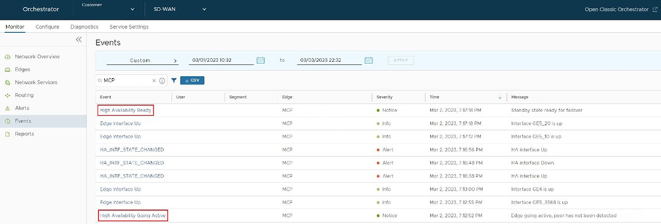
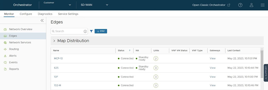
- Wait for the Active Edge to detect and activate the Standby Edge automatically. The Orchestrator Events page displays HA Standby Activated when the Orchestrator successfully activates the Standby Edge.
Figure 27. Monitor Edges 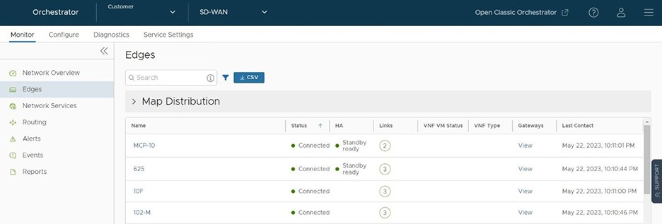
The Standby Edge will then begin to synchronize with the active Edge and reboot automatically during the process.
Connect LAN and WAN Interfaces on Standby
Connect the LAN and WAN interfaces on the Standby Edge mirroring the network connectivity on the Active Edge.
Deactivate High Availability
- Scroll down to the High Availability section and select None.
Figure 29. Deactivate High Availability 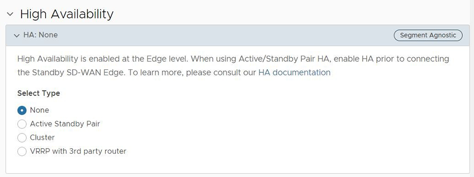
HA Event Details
| HA Event | Description |
|---|---|
| HA_GOING_ACTIVE | The Standby Edge takes over as the Active Edge because it no longer receives heartbeats from its peer. |
| HA_STANDBY_ACTIVATED | When the Active Edge detects a new Standby, it attempts to activate the Edge by sending this event to the Orchestrator. Upon a successful response, Active Edge syncs configurations and data. |
| HA_FAILED | This event typically occurs after the HA pair has formed and the Active Edge no longer hears from the Standby Edge. For example, if the Standby Edge reboots, users receive this message. |
| HA_READY | In this event, the Active Edge detects the Standby Edge. The Orchestrator generates this event after the Standby Edge comes back up and reestablishes the heartbeat. |
| HA_TERMINATED | The Orchestrator generates this event after the system deactivates the HA configuration and successfully applies it to the Edges. |
| HA_ACTIVATION_FAILURE | The Orchestrator generates this event if it is unable to verify the HA activation. Examples:
|
| VCO_IDENTIFIED_HA_FAILOVER | Event message reads: Edge HA Failover Detected.
The Orchestrator detects a High Availability failover on the Edge. |
| VCO_IDENTIFIED_HA_FAILURE | Event message reads: Edge HA Failover Detected.
The Orchestrator detects that the Standby Edge failure. This event includes the serial number of the Edge. |
| HA_UPDATE_FAILOVER_TIME | Event message reads: Updating HA Failover time from ####ms to ####ms.
A user changes the failover time for when an HA Edge will failover based on how long the Edge will wait to receive a heartbeat from the Active Edge. Increasing this value can prevent an Active-Active "Split Brain" state for HA Edges under high load. Configure this value through the HA Failover Detection Time Multiplier, located at on the Orchestrator. |
| HA_RESET_FAILOVER_TIME | Event message reads: Updating HA Failover time from ####ms to ####ms.
When an HA Edge's system remains stable for 60 seconds, the process reduces the failover threshold time by 50%. |