Manage Gateway Pools and Gateways
The network consists of multiple service Gateways deployed at the top-tier network and cloud data centers. The Gateway provides the advantage of cloud-delivered services and optimized paths to all applications, branches, and data centers. Service providers can also deploy their Partner Gateways in their private cloud infrastructure.
This topic contains the following sections:
Manage Gateway Pools
Gateways can be organized into pools that are then assigned to a network. An unpopulated default Gateway pool is available after users install Orchestrator. If required, users can create additional Gateway pools.
As an Operator Super user and Operator Admin user, users can create, clone, manage, download, and delete Gateway pools created by both Operator and Partner users.
To manage Gateway pools, perform the following steps:
- In the Orchestrator UI, select the Gateway Management tab and go to Gateway Pools in the left navigation pane.
The Gateway Pools page appears.
Figure 1. Manage Gateway Pools 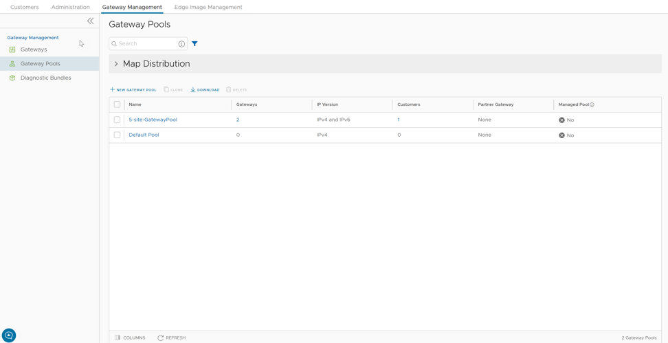
Create New Gateway Pool
- In the New Gateway Pool dialog, configure the following details and click Create.
Figure 2. New Gateway Pool 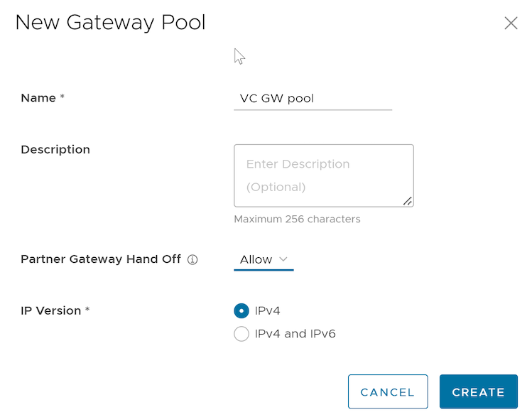
Table 2. New Gateway Pool Field Descriptions Field Description Name Enter a name for the new Gateway pool. Description Enter a description for the Gateway pool. Partner Gateway Hand Off This option determines the method for handing off Gateways to Partners. Select one of the following options from the drop-down list: - None - Select this option when Partner Gateway handoff is not required.
- Allow - Select this option when users want the Gateway pool to support both Partner Gateways and Cloud Gateways.
- Only Partner Gateways - Select this option when Edges in the Enterprise should not be assigned with Cloud Gateways from the pool, and will only be assigned with the Gateways set for an individual Edge.
IP Version Select one of the following address types with which users want to activate the Gateway pool: - IPv4 - Allows adding IPv4-only Gateways.
- IPv4 and IPv6 - Allows adding Gateways with IPv4 and IPv6 addresses.
Note: If users want to use Edges with IPv6 support, then choose IPv4 and IPv6.
Clone a Gateway Pool
- In the Gateway Pools table, select the Gateway pool that users want to clone and click Clone.
The New Gateway Pool dialog appears with the cloned settings.
Figure 3. Clone a Gateway Pool 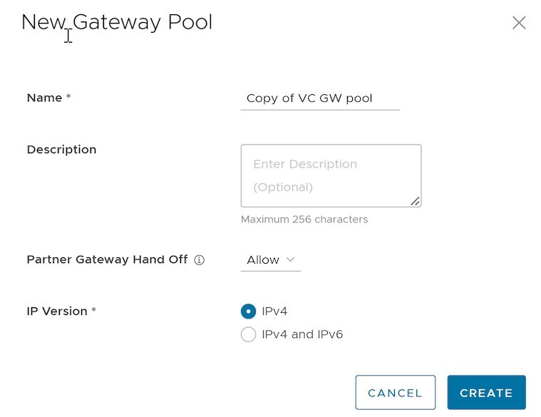
The Gateway pool clones the existing configuration from the selected Gateway pool. If required, modify the details. For additional information on the options, see Create New Gateway Pool.
Configure Gateway Pools
Whenever users create a new Gateway pool or clone a pool, the UI redirects to the Gateway Pool Overview page to configure the Gateway pool's properties.
To configure an existing Gateway pool:
- Configure the following details for the Gateway pool:
Figure 4. Configure Operator Pool 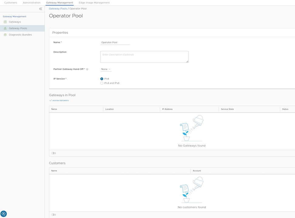
- In the Assign Gateways to Gateway pool dialog, move the required Gateways from the Available pane to the Assigned pane using the Arrows and click Update.
Figure 5. Assign Gateways 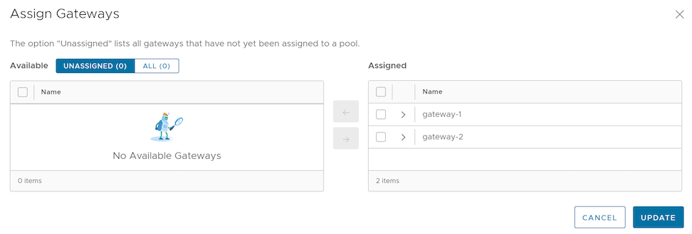
- In the Assign Gateways to Gateway pool dialog, move the required Gateways from the Available pane to the Assigned pane using the Arrows and click Update.
- The Gateways assigned to the selected Gateway pool are displayed as follows:
Figure 6. Assigned Gateways in Pool 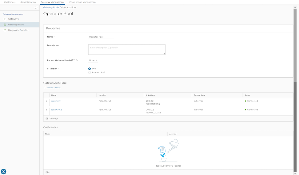
Users can associate the Gateway Pool with either a Partner or a specific Enterprise Customer. After association, the Edges within that Enterprise connect to the available Gateways in the pool to establish their control plane and data paths.
- For a new customer, see Create New Customer.
- For an existing customer, see Configure Customers.
- For a new Partner, see Create New Partner.
- For an existing Partner, see Configure Partner.
Manage Gateways
By default, the Gateways named gateway-1 and gateway-2 are available when users install Orchestrator. If required, users can create additional Gateways.
To manage Gateways, perform the following steps:
- In the Orchestrator UI, select the Gateway Management tab and go to Gateways in the left navigation pane.
The Gateways page appears.
Figure 7. Manage Gateways 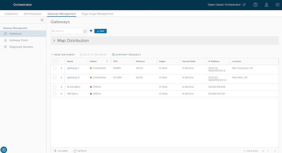
To search a specific Gateway, enter a relevant search text in the Search box. For advanced search, select the filter icon next to the Search box to filter the results by specific criteria.
The Map Distribution section displays the Gateways on a map. Users can click the + and - buttons to zoom in and zoom out the map, respectively.
The Gateways table displays the existing Gateways with the following details:Table 3. Existing Gateways Field Descriptions Field Description Name Name of the Gateway Status Reflects the success or failure of periodic heartbeats sent by mgd to the Orchestrator and does not indicate the status of the data and control plane. The following are the possible statuses: - Connected – Gateway is heart beating successfully to the Orchestrator.
- Degraded – Orchestrator has not heard from the Gateway for at least one minute.
- Offline – Orchestrator has not heard from the Gateway for at least two minutes.
CPU Average CPU utilization of all the cores in the system at the time of the last heartbeat. Memory Percentage usage of the physical memory by all processes in the system as reported by psutil.phymem_usage at the time of the last heartbeat. This is similar to estimating memory usage with the free command. Edges Number of Edges connected to the Gateway at the time of the last heartbeat. Note: Click View next to the number of Edges to view all Edges assigned to the Gateway and their online/offline status in Orchestrator. This option does not display the Edges that are actually connected to the Gateway.Service State The user-configured service state of the Gateway and whether it is eligible to be assigned to new Edges. IP Address The public IP address that the public WAN links of an Edge use to connect to the Gateway. This IP address uniquely identifies the Gateway. If the Gateway is enabled to accommodate both IPv4 and IPv6 addresses, this column displays both IP addresses. Location Location of the Gateway from GeoIP (by default) or as manually entered by the user. This is used for geographic assignment of the Gateway to Edges and should be verified. On the Gateways page, users can perform the following activities:- New Gateway - Creates a new Gateway. See Create New Gateway with New Orchestrator UI.
- Delete Gateway - Deletes a selected Gateway only if it is currently idle. The system prevents users from deleting any Gateway that a Partner or an Enterprise Customer is actively using, ensuring that users do not accidentally disrupt live network traffic or disconnect active Edges.
- Stage to Bastion - Stages a Gateway to the Bastion Orchestrator.
- Unstage from Bastion - Removes a Gateway from the Production Orchestrator.
Note: Stage to Bastion and Unstage from Bastion options are available only when the Bastion Orchestrator feature is enabled using the
session.options.enableBastionOrchestratorsystem property.For additional information, see Bastion Orchestrator Configuration Guide.
- Support Request - Redirects to a Knowledge Base article that has instructions on how to file a support request.
Create New Gateway
To create a Gateway, perform the following steps.
- In the New Gateway dialog, configure the following details:
Figure 8. Create a New Gateway 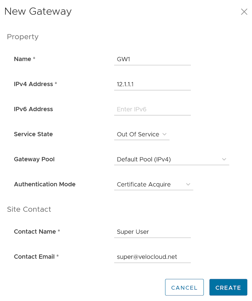
Table 4. New Gateway Field Descriptions Field Description Name Enter a name for the new Gateway. IPv4 Address Enter the IPv4 address of the Gateway. IPv6 Address Enter the IPv6 address of the Gateway. Service State Select the Gateway's service state from the drop-down list. The following options are available: - In Service - The Gateway is connected and available.
- Out of Service - The Gateway is not connected.
- Quiesced - The Gateway service is quiesced or paused. Select this state for backup or maintenance purposes.
Note: The Quiesced and Out of Service states are only applicable for Cloud Gateway deployment.Gateway Pool Select the Gateway Pool from the drop-down list to assign the Gateway to a specific group. Authentication Mode Select the authentication mode of the Gateway from the following available options: - Certificate Not Required - Gateway uses pre-shared key authentication.
- Certificate Acquire - This option is selected by default and instructs the Gateway to acquire a certificate from the Orchestrator's certificate authority, by generating a key pair and sending a certificate signing request to the Orchestrator. After acquisition, the Gateway uses the certificate for authentication with the Orchestrator and for establishing VCMP tunnels.
Note: After acquiring the certificate, the option can be updated to Certificate Required.Note: When users enable the Bastion Orchestrator feature, users must set the Authentication mode for the staged Gateways to either Certificate Acquire or Certificate Required.
- Certificate Required - Gateway uses the PKI certificate. Operators can change the certificate renewal time window for Gateways using the system properties.
Contact Name Enter the name of the Site Contact. Contact Email Enter the Email ID of the Site Contact. Note:- After users have created a Gateway, they cannot modify the IP addresses.
- Release 4.3.x and 4.4.x supports Greenfield deployment of Gateways for IPv6. If users have upgraded a Gateway from a previous version earlier than 4.3.0, they cannot configure the upgraded Gateway with the IPv6 address.
- Release 4.5.0 supports both the Greenfield and Brownfield deployment of Gateways for IPv6. If users have upgraded a Gateway from a previous version earlier than 4.5.0, they can dynamically configure an IPv6 address for the Gateway.
- The system does not support IPv4/IPv6 dual-stack mode for Bastion Orchestrator configurations.
After users create a new Gateway, the system redirects them to the Configure Gateways page. From here, users can configure additional settings, such as BGP handoff details, location parameters, and pool assignments, to fully integrate the Gateway into your network
To configure additional Gateway settings, see Configure Gateways.
Configure Gateways
To configure an existing Gateway, perform the following steps
- On the Overview tab, configure the following details:
Figure 9. Configure Gateways 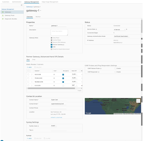
Table 5. Gateway Option Descriptions Option Description Status Users can configure the following details: - Status: Displays the status of the Gateway, which reflects the success or failure of periodic heartbeats sent to the Orchestrator. The following are the available statuses:
- Connected: Gateway is heart beating successfully to the Orchestrator.
- Degraded: Orchestrator has not heard from the Gateway for at least one minute.
- Offline: Orchestrator has not heard from the Gateway for at least two minutes.
- Service State: Select the Service State of the Gateway from the following available options:
- In Service: The Gateway is connected and available for Primary or secondary tunnel assignments. When the Service state of the Gateway is switched from 'Out Of Service' to 'In Service', the Primary or Secondary assignments, Super Gateways, and Edge-to-Edge routes are recalculated for each Enterprise using the Gateway.
- Pending Service: The Gateway is connected and awaiting tunnel assignments.
- Out of Service: The Gateway is not connected or not available for any assignments. The system removes all existing assignments.
- Quiesced: When users quiesce or pause the Gateway service, the system prevents the addition of any new tunnels or Non-SD-WAN (NSD) sites. However, the existing assignments would remain in the Gateway. Select this state for backup or maintenance purposes.
Note: The Quiesced and Out of Service states are only applicable for Cloud Gateway deployment.When users quiesce the Gateway service, Orchestrator provides self-service migration functionality that allows users to migrate from an existing Gateway to a new Gateway without Operator support.
For additional information, see Quiesce Gateways.
Note: VeloCloud SD-WAN does not support Self-service migration on Partner Gateways.
Connected Edges Displays the number of Edges connected to the Gateway. This option is displayed only when the Gateway is activated. Gateway Authentication Mode Select the authentication mode of the Gateway from the drop-down menu: - Certificate Deactivated: Gateway uses a pre-shared key for authentication. If users change the mode from Certificate Deactivated to:
- Certificate Acquire: Tunnels in PSK mode are not affected. Only tunnels with Gateways get impacted. These tunnels are reconnected based on the certificate. All tunnels configured in PSK mode remain active, and no traffic disruptions are observed.
- Certificate Required: The Orchestrator prevents users from making this change directly. Users must first change the mode to Certificate Acquire, and then change it to Certificate Required. This helps avoid heartbeat loss to the Orchestrator when Edge is assigned a certificate.
- Certificate Acquire: The system selects this option by default and instructs the Gateway to acquire a certificate from the Orchestrator's certificate authority, by generating a key pair and sending a certificate signing request to the Orchestrator. After acquisition, the Gateway uses the certificate for authentication with the Orchestrator and for establishing VCMP tunnels. If users change the mode from Certificate Acquire to:
- Certificate Deactivated: PSK-based tunnels are not impacted. Tunnels with Gateways and all certificate-based tunnels are disconnected and reconnected based on PSK.
- Certificate Required: All peers configured with PSK mode are disconnected and cannot connect to the Hub. All current RSA tunnels stay active.
While the Hub is in Certificate Acquire mode, the system reestablishes all certificate-based tunnels using a new certificate. This process ensures a seamless transition to updated credentials without manual intervention. Importantly, the system maintains all PSK-based tunnels without interruption, as these connections do not rely on the certificate exchange process.
Note: After acquiring the certificate, users can update the option to Certificate Required. - Certificate Required: Gateway uses the PKI certificate. Operators can change the certificate renewal time window for Gateways using the system property
gateway.certificate.renewal.window. If users change the mode from Certificate Required to:- Certificate Deactivated: All peers with an RSA tunnel are disconnected and cannot reconnect. All peers configured in PSK mode remain active, and no disruption is observed in traffic.
- Certificate Acquire: All peers configured in PSK mode reconnect with the Hub/Gateway. All current RSA tunnels stay active.
Note:- When the Gateway certificate is revoked, the Gateway does not receive the certificate revocation list (CRL), as it loses the Transport Layer Security (TLS) connection immediately. Anyway, the Gateway is still operable.
- The current QuickSec design checks the validity of CRL time. The CRL's time validity must match the current time at Edges for the CRL to affect a newly established connection. To implement this, ensure the Orchestrator time is properly updated to match the Edges' date and time.
IP Address Displays the public IP address that the public WAN links of an Edge use to connect to the Gateway. This IP address uniquely identifies the Gateway. If users have configured the Gateway with both IPv4 and IPv6 addresses, this field displays both IP addresses. If users have created an IPv4-only Gateway or if there is an existing IPv4 Gateway upgraded from previous versions, users can enter the IPv6 address to support the dual stack. After saving the changes, the IPv6 address is not sent to the Edges immediately. Users can trigger the rebalance operation to push the IPv6 address to the customer and the associated Edges manually, or the IPv6 address is sent to the Edges during the next Control Plane update. Note: Adding an IPv6 address is a one-time activity. After users save the changes, they cannot modify the IP addresses.CAUTION: An incorrectly configured IPv6 address when pushed to Edges might cause IPv6 tunnelling to the IPv6 Gateway to fail. In such cases, users need to deactivate the Gateway and create a new one to activate both the IPv4 and IPv6 addresses.Contact & Location Displays the existing contact details. If required, users can modify the information. NSD IP Portability Beginning with the 6.0 Orchestrator release, selecting this option will activate NSD IP Portability for the Gateway. Portable NSD IPs allow Operators to move NSD configurations to different Gateways in the POP without requiring the customer to reconfigure their tunnels. When the NSD Portability checkbox is selected, the Orchestrator fetches the following data, such as Point of Presence (PoP) name, NSD Virtual IPv4 Address, and NSD Virtual IPv6 Prefix currently assigned to the Gateway from the Global Services Manager (GSM) and displays it. Click Refresh POP to retrieve the current and updated data. Note: For the "NSD Portability" feature to work as designed, the Operators must ensure that the Gateways are associated with the corresponding PoPs in GSM.Figure 10. NSD IP Portability 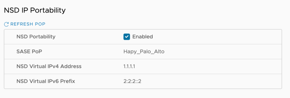 Important: There are two important caveats with NSD IP Portability:
- NSD peers must operate as an IKE responder. In the past, some configurations would permit an initiator-only set up, but that will no longer function.
- Peers must allow Network Address Translation Traversal (NAT-T). The current implementation of NSD Portable IP uses NAT, which is implemented internally within the POP.
Syslog Settings Beginning with the 4.5 release, Gateways can export NAT information via a remote syslog server or via Telegraph to the desired destination. For additional information, see the Configure NAT Entry Syslog for Gateways section in the VeloCloud SD-WAN Operator Guide. Customer Usage Displays usage details for different types of Gateways assigned to customers. Pool Membership Displays the details of the Gateway Pools to which users have assigned the current Gateway. Partner Gateway (Advanced Handoff) Details This section is available only if users select the Partner Gateway checkbox. Users can configure advanced handoff settings for the Partner Gateway. For additional information, see the Partner Gateway (Advanced Handoff) Details section later. Partner Gateway (Advanced Handoff) Details - Users can configure the following advanced handoff settings for the Partner Gateway:
CAUTION: VeloCloud does not recommend pushing IPv6 configurations to Partner Gateways running software versions earlier than 5.0.Table 6. Partner Gateway Option Descriptions Option Description Static Routes | Subnets - Specify the subnets or routes that the Gateway should advertise to the Edge. This is global per Gateway and applies to all customers. With BGP, this section is used only if there is a shared subnet that all customers need to access and if NAT handoff is required. Remove the unused subnets from the Static Route list if users do not have any subnets to advertise to the Edge and have the handoff of type NAT.
Users can select the IPv4 or the IPv6 tab to configure the corresponding address type for the Subnets.
Subnets Enter the IPv4 or IPv6 address of the Static Route Subnet that the Gateway should advertise to the Edge. Cost Enter the cost to apply weighting on the routes. The range is from 0 to 255. Encrypt Select the checkbox to encrypt the traffic between Edge and Gateway. Hand off Select the handoff type as VLAN or NAT. Description Optionally, enter a descriptive text for the static route. ICMP Probes and Ping Responders Settings ICMP Failover Probe - The Gateway uses an an ICMP probe to check the reachability of a particular IP address. It notifies the Edge to failover to the secondary Gateway if the IP address is unreachable. This option supports only IPv4 addresses. VLAN Tagging Select the VLAN tag from the drop-down list to apply to the ICMP probe packets. The following are the available options: - None: Untagged
- 802.1q: Single VLAN tag
- 802.1ad: / QinQ(0x8100) / QinQ(0x9100): Dual VLAN tag
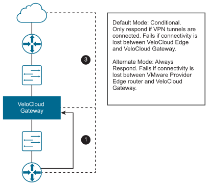
Destination IP address Enter the IP address to be pinged. Frequency Enter the time interval, in seconds, to send the ping request. The range is from 1 to 60 seconds. Threshold Enter the number of times the system can miss ping replies before it marks the routes as unreachable.The range is from 1 to 10. ICMP Responder - Allows the Gateway to respond to ICMP probes from the next-hop router when the tunnels are up. This option supports only IPv4 addresses. IP address Enter the virtual IP address that will respond to the ping requests. Mode Select one of the following modes from the drop-down list: - Conditional - Gateway responds to ICMP requests only when the service is up and at least one tunnel is up.
- Always - Gateway always responds to the ICMP request from the peer.
Note: The ICMP probe parameters are optional and recommended only if users want to use ICMP to check the Gateway's health. With BGP support on the Partner Gateway, using an ICMP probe for failover and route convergence is no longer required. For additional information on configuring BGP support and handoff settings for a Partner Gateway, see Configure a Handoff Operator. - Status: Displays the status of the Gateway, which reflects the success or failure of periodic heartbeats sent to the Orchestrator. The following are the available statuses:
Upgrade Orchestrator for Dual Stack Support
- Upgrade Orchestrator to release 5.0.0.
- Add an IPv6 address in the Orchestrator Shell. The following example shows a sample configuration:
vcadmin@vco:~$ cat /etc/netplan/50-cloud-init.yaml network: ethernets: eth0: addresses: [169.254.8.2/29, 'fd00:aaaa:0:1::2/64'] routes: - {metric: 1, to: 0.0.0.0/0, via: 169.254.8.1} - {metric: 1, to: '0::0/0', via: 'fd00:aaaa:0:1::1'} renderer: networkd version: 2 - In the Orchestrator's Operator portal, navigate to , and select a Profile.
- On the Operator Profiles page of the selected Profile, navigate to the Management Settings section and enter the IPv6 address configured in Orchestrator Shell.
Figure 11. Configure Operator Profile 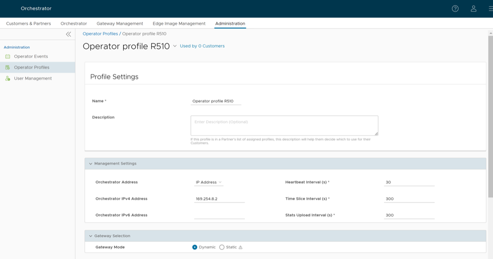
- Click Save Changes.
Configure IPv6 Address on Gateways
Prerequisites
Ensure that the Orchestrator is running version 5.0.0 as described in Upgrade Orchestrator for Dual Stack Support.
Deploy VeloCloud Gateway on AWS
- While migrating Gateways to the cloud, it is recommended to destroy and create a new instance with IPv6 enabled.
- When a VeloCloud Gateway is freshly deployed in the AWS portal with IPv6 selected, it is required to use only static IPv4/IPv6 address assignment on the Gateway's interfaces, as VeloCloud SD-WAN does not support DHCP on the Gateway side.
Set up IPv6 Address on Gateways for a New Deployment
Set up IPv6 Address on Gateways Upgraded from Previous Release
Partner Gateways
Users can configure a Partner Gateway with multiple subnets, and for each subnet, users can assign a specific handoff type: Network Address Translation (NAT) or Virtual Local Area Network (VLAN). Additionally, users can define a relative cost for each path and specify whether the system should encrypt traffic, giving users granular control over how data exits the SD-WAN overlay and enters your private network.
The following examples illustrate two use cases for Partner Gateways configuration.
Gateway Configuration Use Case #1
In the following illustration, the Gateway connects via VLAN/VRF mode to a Virtual Route Forwarding (VRF) instance that lacks public Internet access. However, the Partner Gateway must be able to contact the Orchestrator in the public cloud, and there must be a path to reach the cloud. The Gateway can selectively NAT certain traffic (such as the IP address of an Orchestrator, or the subnets used to reach public DNS servers) even though it is operating in VLAN/VRF mode.
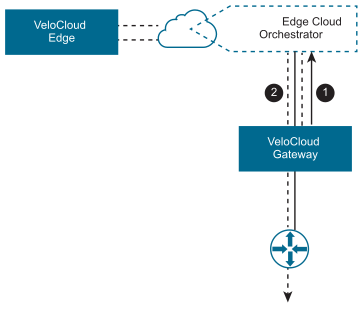
- #1- The system routes Orchestrator traffic using IP addresses to NAT.
- #2- The system routes Corporate traffic through subnets to VLAN/VRF.
Gateway Configuration Use Case #2
It is common for a Partner Gateway to tie into a corporate network, providing connectivity to legacy sites. This need can occur even when not all corporate sites have been converted to the Arista network. For this use case, it is necessary to specify traffic by subnet on the Partner Gateway. Users can configure each subnet to encrypt network traffic to ensure data remains secure as it passes through the Partner Gateway handoff.
0.0.0.0/0 subnet to allow all traffic (which is a common configuration), all that would be required is to add the private subnet for your legacy sites and mark it as encrypted.

- #1- Subnet (e.g.,
10.0.0.0/8) defined for Legacy Sites and marked for encryption. The system transmits traffic between the Edge and the Gateway over an Internet Protocol Security (IPsec) tunnel. - #2- The system sends the remaining traffic unencrypted to the Edge, and then to its final destination.
- For an IPsec tunnel via the Partner Gateway, a VCMP tunnel failure causes existing flows to time out. The expected behavior for existing flows is to remain on the current path. Any new flow will begin to go (directly), keeping the tunnel down.
- Select application map flags
mustUseGatewayanddropIfPartnerGatewayDownto force or drop traffic through the Gateway until the path restores. If these flags are not active, a flow flush is required after the tunnel path restores.
Partner Gateway Resiliency
The Partner Gateway provides resiliency by detecting failures and failing over to an alternate Partner Gateway. This includes the ability of a Partner Gateway to detect failure conditions and for the surrounding infrastructure to detect failures of the Gateway itself.
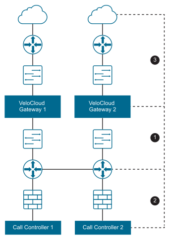
| Failure Zone | Component | Description |
|---|---|---|
| 1 | Provider Edge | The Provider Edge is one instance in which failure can be detected either from the Provider Edge router pinging the Gateway, or from the Gateway to the Provider Edge router. |
| 2 | Call Controller | The Gateway should be able to ping the Provider Edge router or Call Controller to verify connectivity. |
| 3 | WAN | The Gateway should have a stateful ping responder that responds only if the Wide Area Network (WAN) zone is available. |

The Partner Gateway also supports configurable route costs, enabling more flexible failure scenarios. Finally, users can assign a handoff type that applies neither Network Address Translation (NAT) nor Virtual Local Area Network (VLAN) tags to the packets. In this configuration, the Gateway passes the packets directly to the Provider Edge router.
ICMP Failover Probes
This section discusses ICMP failover probes.
To address a failure in zones #1 or #2 of the Gateway topology diagram, the Gateway supports the optional ability to send failover probes. These probes will ping a single destination IP address at the specified frequency. If the threshold for successive missed ping replies is exceeded, the VeloCloud Gateway will mark the Gateway’s routes as unreachable. Even after the system marks the routes as unreachable due to a probe failure, the Edge continues to send probes to the target. This constant monitoring ensures that as soon as the link or service recovers, the system automatically detects the restored connectivity and reactivates the routes. If the same threshold is exceeded for successive successful ping replies, the Gateway will mark the routes as reachable again.
Example Scenario
- VeloCloud Edges connect to the primary Gateway. The primary Gateway marks routes as reachable.
- The Primary Gateway fails to receive a reply for three successive probes (~6 seconds).
- The Primary Gateway marks routes as unreachable and notifies all connected Edges.
- Edges begin routing Gateway traffic via the alternate Gateway.
- Connectivity is restored, and the primary Gateway receives three successive probe replies.
- The Primary Gateway marks routes as reachable and communicates this to all connected Edges.
- Edges route traffic back through the primary Gateway.
In failure scenario #1, users can configure the system to ping an IP address directly on the Provider Edge (PE) router. This allows users to monitor the health of the immediate physical link or the next-hop availability. In failure scenario #2, users can direct the ping toward the actual Call Controller, enabling the Edge to verify end-to-end reachability for critical voice services.
Stateful Ping Responder
To address failures in zones #2 or #3 of the Partner Gateway topology diagram, the Gateway supports an optional stateful ping responder. This allows the configuration of a virtual IP address (which must be different from the interface IP address) within the Gateway that will, based on configuration, either respond to pings always (Gateway service is running) or conditionally based on Wide Area Network (WAN) connectivity (the Gateway has Virtual Private Network (VPN) tunnels connected).
This can be used in failure scenario #1 by having the Provider Edge router ping the ping responder, as the Gateway becoming unreachable would cause the IP SLA on the Provider Edge router to fail. This could also be used in failure scenario #3 by having the Gateway only respond if VPN tunnels are connected- this is similar to the behavior with BGP (no clients connected means no client routes).
!IP-SLA configuration to send ICMP request to gateway virtual IP
ip sla 1
icmp-echo 192.168.10.10 source-ip 192.168.10.1
vrf CUSTOMER1
threshold 1000
timeout 1000
frequency 2
ip sla schedule 1 life forever start-time now

!tracking the IP SLA for its reachability
track 1 ip sla 1 reachability

!all the routes will reachable only when SLA probe succeeds
ip route vrf CUSTOMER1 0.0.0.0 0.0.0.0 192.168.11.101 track 1
ip route vrf CUSTOMER2 0.0.0.0 0.0.0.0 192.168.12.101 track 1
ip route vrf CUSTOMER1 10.0.0.0 255.0.0.0 192.168.10.10 track 1
ip route vrf CUSTOMER2 10.0.0.0 255.0.0.0 192.168.10.10 track 1
ip route vrf CUSTOMER1 192.168.100.0 255.255.255.0 192.168.10.10 track 1
Caveats When Using NAT Hand-off Mode
- In VLAN hand-off mode, the Partner Gateway can listen on any IP address if it is reachable from the PE router (including its interface IP). For NAT hand-off mode, the Partner Gateway will not respond if the ICMP request comes to its own interface (WAN) IP address.
-
VeloCloud does not support reverse flow in the NAT hand-off mode.
Active/Backup Subnets
This section discusses how to configure active and backup subnets for a Partner Gateway.
Subnets on a Partner Gateway
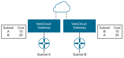
When configuring subnets on a Partner Gateway, users input each subnet along with an optional description to identify the traffic path. By assigning a value to the Cost field, users control route weighting; the system prioritizes lower-cost routes over higher-cost routes to determine the most efficient path for your data. The following figure shows Cost settings per subnet.
Monitor Gateways
To monitor the Gateways:
- The Gateways page displays the list of available Gateways.
Figure 18. Monitor Gateways 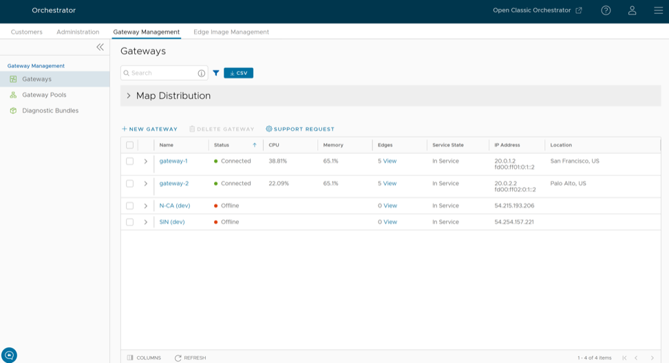
- Click the Gateway link to view the details of the selected Gateway.
Figure 19. View Selected Gateway Details 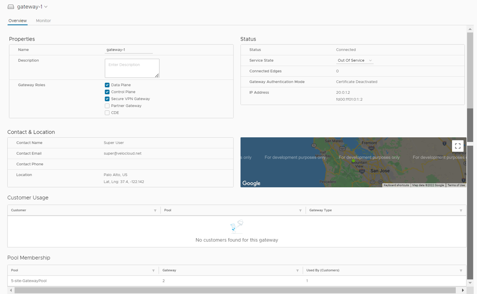
The Overview tab displays the properties, status, location, customer usage, and Gateway Pool of the selected Gateway.
Note: On the Overview tab, users can modify the Name and Description of the selected Gateway, and choose a different Service State. To configure the other options, navigate to the Gateways page in the Operator portal. - Click the Monitor tab to view the usage details of the selected Gateways.
Figure 20. View Selected Gateway Usage Details 
At the top of the page, select a specific time period to view Gateway details for that period.
The page displays a graphical representation of usage details of the following parameters for the period of the selected time duration, along with the minimum, maximum, and average values:- CPU Percentage - Percentage of CPU usage.
- Memory Usage - Percentage of memory usage.
- Flow Counts - Count of traffic flow.
- Over Capacity Drops - Total number of packets dropped due to over capacity since the last sync interval. Occasional drops are expected, typically due to a large traffic surge. However, a consistent increase in drops usually indicates a Gateway capacity issue.
- Tunnel Count - Count of tunnel sessions for both the IPv4 and IPv6 addresses.
Hover over the graphs to view additional details.
VeloCloud Gateway Migration
The VeloCloud Orchestrator offers self-service migration functionality, enabling migration from an existing Gateway to a new Gateway without requiring your Operator’s support.
- Achieving operational efficiency.
- Decommissioning old Gateways.
Gateway configurations define specific roles. For example, a Gateway with a data-plane role forwards data-plane traffic from source to destination. Similarly, a Gateway with a Control Plane role is referred to as a Super Gateway and is assigned to an Enterprise. The Super Gateway establishes connections with all Edges within the Enterprise. Additionally, a Gateway with the Secure Virtual Private Network (VPN) role establishes an Internet Protocol Security (IPSec) tunnel to a Non SD-WAN Destination (NSD). The migration steps may vary based on the role configured for the Gateway. For additional information about the Gateway roles, see the Configure Gateways” section.
The following figure illustrates the migration process of the Secure VPN Gateway:
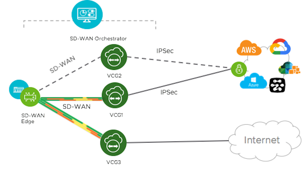
In this example, a VeloCloud Edge connects to an NSD through a Secure VPN Gateway, VCG1. The Orchestrator currently flags VCG1 for decommissioning. Before decommissioning, the administrator creates a new Gateway, VCG2, and assigns VCG2 the same role and attaches it to the same Gateway pool as VCG1, allowing VCG2 to replace the original Gateway. The administrator then changes VCG1's service state to "Quiesced," preventing the system from adding new tunnels or NSDs to VCG1. However, VCG1 retains its existing assignments. After the administrator updates the VCG2 IP address configuration in the NSD, VCG2 establishes an IPSec tunnel to the NSD and switches the traffic from VCG1 to VCG2. The administrator decommissions VCG1 after confirming it contains no remaining sessions.
Following is the high-level workflow of Secure VPN Gateway migration based on the User roles:
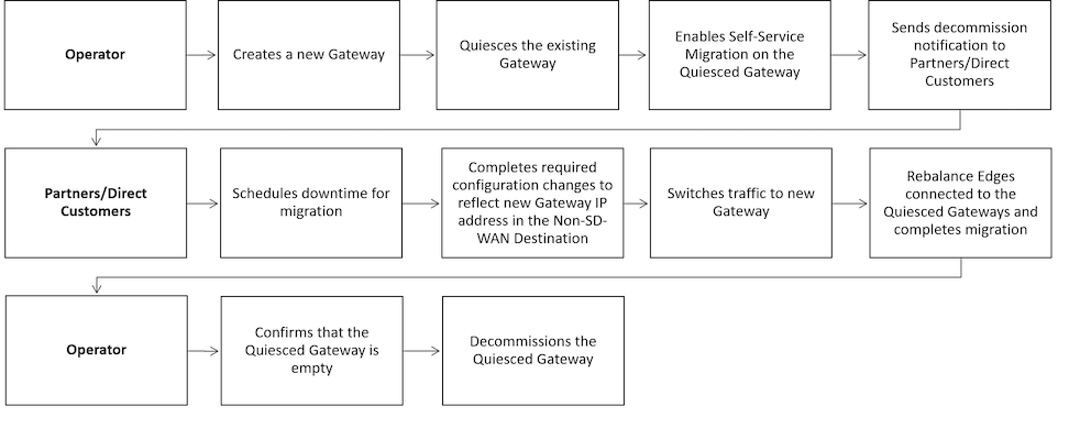
Limitations of VeloCloud Gateway Migration
- Partner Gateways do not support self-service migration.
- There will be a minimum service disruption based on the time taken to switch Non SD-WAN Destinations (NSDs) from the quiesced Gateway to the new Gateway and to rebalance the Edges connected to the quiesced Gateway.
- If an NSD uses redundant Gateways and the administrator quiesces one Gateway, the remaining redundant Gateway cannot replace it.
- During self-service migration of a quiesced Gateway, the replacement Gateway must have the same Gateway Authentication mode as the quiesced Gateway.
- When a customer deploys an NSD via Gateway with Border Gateway Protocol (BGP) enabled, the Self-Service Gateway Migration feature does not migrate BGP configurations to the new Gateway. Consequently, the system drops all BGP sessions after the migration completes.
In this scenario, the existing Gateway assigned to the NSD is in a quiesced state and requires migration to another Gateway. The customer then navigates to on the Orchestrator and initiates the Gateway Migration process to move their NSD to a different Gateway. Post-migration, the new Gateway fails to populate the BGP Local ASN and Router ID fields, preventing NSD BGP sessions from establishing and causing the loss of all routes. Traffic remains disrupted until the administrator manually recreates all BGP settings.
This is a Day 1 issue, and while the Gateway Migration feature accounts for many critical NSD settings, the NSD's BGP settings that are not accounted for, and their loss post-migration, are an expected behavior.Workaround: Gateway migration should be done only during a maintenance window. Before the migration, the user should document all BGP settings and manually reconfigure them after the migration to minimize impact on customer users.
Quiesce Gateways
Before quiescing the existing Gateway, ensure that users create a new Gateway as a replacement. Assign the new Gateway with the same role and attach it to the same Gateway pool as the existing Gateway. For instructions, see the Manage Gateway Pools and Gateways section. Review the VeloCloud Gateway Migration- Limitations before proceeding with Gateway quiescing.
To quiesce the Gateway and enable self-service migration:
- Select the Gateway link that the user wants to quiesce.
The Gateway details appear on the Overview tab.
Figure 23. Configure Quiesce Gateway 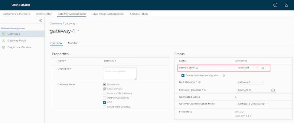
Send decommission notification to impacted Partners and direct customers. The notification email includes the migration deadline and detailed instructions for migrating the Edges and NSDs from the quiesced Gateway to the new Gateway.
Decommission Quiesced Gateways
If any Partners or direct customers have not yet migrated from the quiesced Gateways, follow up with them to ensure they migrate from the quiesced Gateways. Verify that the quiesced Gateway is empty and then decommission it.
To decommission a quiesced Gateway:
- Select the Gateway link the user wants to decommission.
The Gateway details appear on the Overview tab.
Figure 24. Decommission Quiesced Gateways 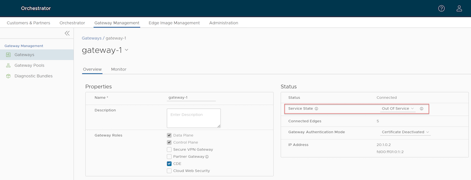
Diagnostic Bundles for Gateways
Request Diagnostic Bundles for Gateways
- In the Request Diagnostic Bundle dialog, configure the following details and click Submit.
Figure 25. Request Diagnostic Bundle 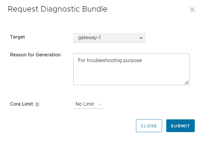
Table 8. Request Diagnostic Bundle Field Descriptions Field Description Target Select the target Gateway from the drop-down list. The system collects data from the selected Gateway. Reason for Generation Optionally, the user can enter the reason for generating the bundle. Core Limit Select a Core Limit value from the drop-down to reduce the size of the uploaded bundle when Internet connectivity is experiencing issues. The Diagnostic Bundles page displays details of the bundle being generated, including its status.
To search a specific diagnostic bundle, enter a relevant search text in the Search box. For advanced search, select the filter icon next to the Search box to filter the results by specific criteria.
Figure 26. Manage Diagnostic Bundles 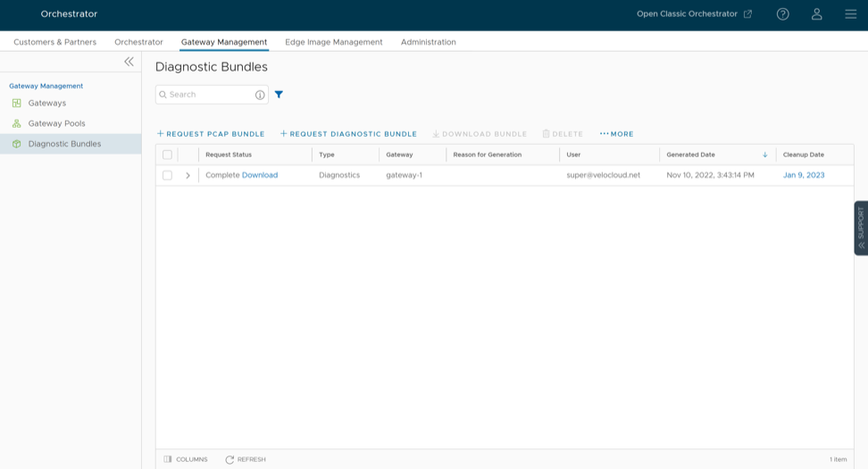
Download Diagnostic Bundle
To download a generated bundle, click the link next to Complete in the Request Status column, or select the bundle, then click Download Bundle. The system downloads the bundle as a ZIP file.
Users can send the downloaded bundle to the Arista Support representative for debugging the data.
Delete Diagnostic Bundle
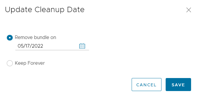
In the Update Cleanup Date dialog, users can choose the specific date when the system will delete the selected bundle. Setting this date allows users to manage storage effectively by ensuring that temporary diagnostic files do not persist longer than necessary for investigation.
If the user wants to retain the bundle, select the Keep Forever checkbox to prevent it from being automatically deleted.
To delete a bundle manually, select the bundle and click Delete.
Request Packet Capture Bundle for Gateways
The Operator Super user and Operator Admin user can create, manage, download, and delete Packet Capture (PCAP) bundles for Gateways created by both Operator and Partner users.
To generate a PCAP bundle:
- In the Request PCAP Bundle dialog, configure the following details and click Generate.
Figure 28. Request PCAP Bundle 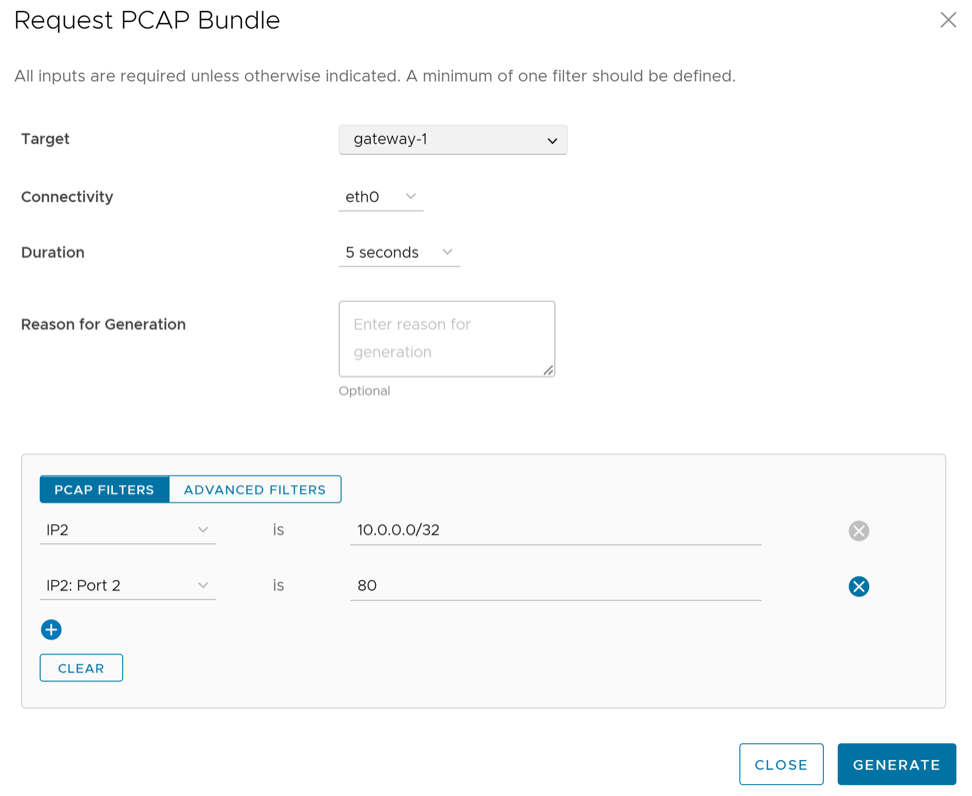
Table 9. Request PCAP Bundle Field Descriptions Field Description Target Choose the target Gateway from the drop-down list. The system collects the packets from the selected Gateway. Connectivity Choose an interface or an Edge ID from the drop-down list. The system collects the packets from the selected interface or Edge associated with the Gateway. Duration Choose the time in seconds. The system collects the packets for the selected duration. The default value is 5 seconds. Reason for Generation The user can optionally enter the reason for generating the bundle. PCAP Filters Users can define PCAP filters to control exactly which packet data the system generates by selecting the following options: - IP1- Enter an IPv4 address, or an IPv6 address, or a Subnet mask.
- IP2- Enter an IPv4 address, or an IPv6 address, or a Subnet mask.
- IP1:Port1- Enter a Port ID associated with IP1.
- IP2:Port2- Enter a Port ID associated with IP2.
- Protocol- Select a protocol from the list.
Note: If users choose to utilize the PCAP filtering capability, they must define at least one filter.Advanced Filters Users can define free-form filters to control which PCAP data the system generates precisely. The Diagnostic Bundles page displays details of the PCAP bundle being generated, including its status.