Print

Site Configurations

Topologies for data centers that include an Hub and branch configurations that are configured using both MPLS and Internet connections. Legacy branch configurations (those without a Edge ) are included, and hub and branch configurations are modified given the presence of the legacy branches.

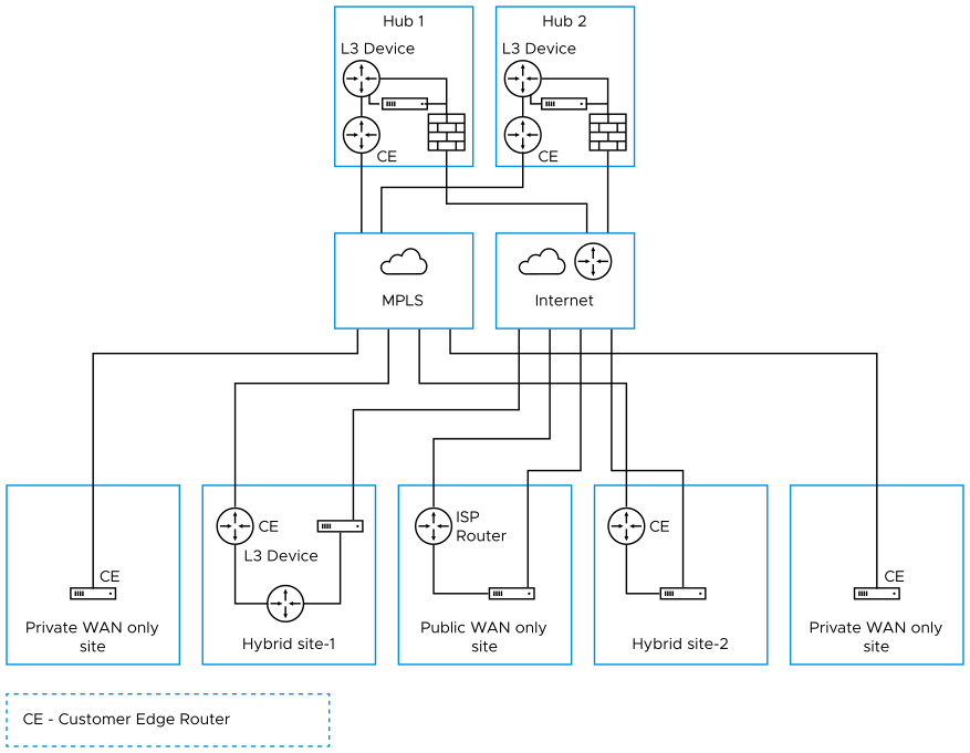
The diagram below shows an example topology that includes two data center Hubs and different variations of branch topologies interconnected using MPLS and the Internet. This example will be used to describe the individual tasks required for data center and branch configurations. It is assumed that you are familiar with concepts and configuration details in earlier sections of this documentation. This section will primarily focus on configuring Networks, Profile Device Settings, and Edge configuration required for each topology.

Additional configuration steps for traffic redirection, control routing (such as for backhaul traffic and VPNs), and for Edge failover are also included.

Figure 1. Site Configurations

This section primarily focuses on the configuration required for a topology that includes different types of data center and branch locations, and explains the Network, Profile/Edge Device Settings, and Profile/Edge Business Policies required to complete the configurations. Some ancillary configuration steps that may be necessary for a complete configuration – such as for Network Services, Device Wi-Fi Radio, Authentication, SNMP, and Netflow settings – are not described.

Data Center Configurations

An Edge in a data center can act as a Hub to direct traffic to/from branches. The Edge can be used to manage both MPLS and Internet traffic. The Hub in a data center can be configured in a one-arm or two-arm configuration. In addition, a data center can be used as a backup. Datacenter Edge capacity planning must be thoroughly done to enable the datacenter Hubs to handle the number of tunnels, flows and traffic load from branches. Also, the Edge model must be selected accordingly. For additional information, consult the Arista Support or Solution Architect team.

The following table describes the various designs with different options, about how Edge can be inserted into the topology:

Table 1. Data Center Configurations
Option Description
Hub 1 Data Center or regional Hub site with Edge deployed in two-arm topology.
Hub 2 Data Center or regional Hub site with Edge deployed in one-arm topology (same interface carries multiple WAN links).
Private WAN link(s) only Site Classic MPLS sites.
Hybrid Site-1 Edge is deployed off-path. Edge creates overlay across both MPLS and Internet paths. Traffic is first diverted to the Edge.
Hybrid Site-2 Edge is deployed in-path as the default gateway. It is always the default gateway. This topology is simpler but makes Edge a single point of failure and may require HA.
Public WAN link(s) only Site Dual-Internet site (one of the links is behind a NAT router).
Note: These are some common deployment methods used to explain the concept. The Customer topology may not be limited to these methods.

Configure Branch and Hub

This section provides an overview of configuring Edge in a two-arm configuration.

Overview

To configure the Edge in a two-arm configuration:
  1. Configure and activate Hub 1
  2. Configure and activate the Hybrid Site-1
  3. Activate branch-to-Hub tunnel (Hybrid Site-1 to Hub 1)
  4. Configure and activate Public WAN only Site
  5. Configure and activate Hub 2
  6. Configure and activate Hybrid Site-2

The following sections describe the steps in more detail.

  1. Configure and Activate Hub 1: This step helps you understand the typical workflow of how to bring up Edge at the Hub location. Edge is deployed with two interfaces (one interface for each WAN link).

    Below is an example of the wiring and IP address information.

    Figure 2. Configure and Activate Hub 1
  2. Activate the Edge in Default Profile
    1. Login to the Orchestrator.
    2. The default VPN profile allows the activation of the Edge.
  3. Activate Hub 1 Edge: Go to Configure > Edges and add a new Edge. Specify the correct model and the profile (we use the Branch VPN Profile).
    1. Go to the Hub Edge (DC1-VCE) and follow the normal activation process. If you already have the email feature set up, an activation email will be sent to that email address. Otherwise, you can go to the device setting page to get the activation URL.
    2. Copy the activation URL and paste that to the browser on the PC connected to the Edge or just additional on the activation URL from the PC browser.
    3. Select the Activate button.
    4. Now the DC1-VCE data center Hub should be up. Go to Monitor > Edges . Select the Edge Overview tab. The public WAN link capacity is detected along with the correct public IP 238.162.42.202 and ISP.
    5. Go to Configure > Edges and select DC1-VCE. Go to the Device tab and scroll down to the Interface Settings.
    6. You will see that the registration process notifies the Orchestrator of the static WAN IP address and gateway that was configured through the local UI. The configuration on the Orchestrator will be updated accordingly.
    7. Scroll down to the WAN Settings section. The Link Type should be automatically identified as Public Wired.
  4. Configure the Private WAN Link on Hub 1 Edge
    1. Configure the private MPLS Edge WAN interface directly from the Orchestrator. Go to Configure > Edges and choose DC1-VCE. Go to the Device tab and scroll down to the Interface Settings section. Configure static IP on GE3 as 172.31.2.1/24 and default gateway of 172.31.2.2. Under WAN Overlay, select User Defined Overlay. This will allow us to define a WAN link manually in the next step.
    2. Under WAN Settings, additional the Add User Defined WAN Overlay button.
    3. Define the WAN overlay for the MPLS path. Select the Link Type as Private and specify the next-hop IP (172.31.2.2) of the WAN link in the IP Address field. Choose the GE3 as the interface. Select the Advanced button.
      Note:
      Tip: The Hub site normally has more bandwidth than the branches. If we choose the bandwidth to be auto-discovered, the Hub site will run a bandwidth test with its first peer, e.g. the first branch that comes up, and will end up discovering an incorrect WAN bandwidth. For the Hub site, you should always define the WAN bandwidth manually, and that is done in the advanced settings.
    4. The private WAN bandwidth is specified in advanced settings. The screen shot below shows an example of 5 Mbps upstream and downstream bandwidth for a symmetric MPLS link at the Hub.
    5. Validate that the WAN link is configured and save the changes.
      You are done with configuring the Edge on the Hub. You will not see the User Defined MPLS overlay that you just added until you activate a branch Edge.
  5. Configure Static Route to LAN Network Behind L3 Switch: Add a static route to the 172.30.0.0/24 subnet through the L3 switch. You need to specify the interface GE3 to use for routing to the next hop. Make sure you select the Advertise check box so other Edge can learn about this subnet behind L3 switch. For additional information, see Configure Static Route Settings.
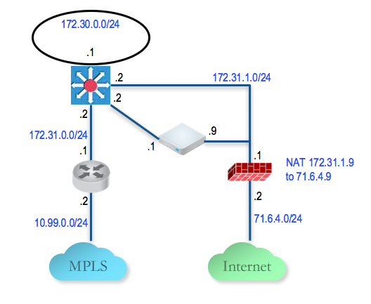
  6. Configure and Activate Hybrid Site-1: This step helps you understand the typical workflow of how to insert the Edge at a Hybrid Site-1. The Edge is inserted off-path and relies on the L3 switch to redirect traffic to it. Below is an example of the wiring and IP address information:
    Figure 3. Configure and Activate Hybrid Site-1
  7. Configure the Private WAN Link on the Hybrid Site-1 Edge: At this point, we need to build the IP connectivity from the Edge towards the L3 switch.
    1. Go to Configure > Edges , select the Hybrid Site-1-VCE and go to the Device tab and scroll down to the Interface Settings section. Configure static IP on GE3 as 10.12.1.1/24 and default gateway of 10.12.1.2. Under WAN Overlay, select User Defined Overlay. This allows to define a WAN link manually.
    2. Under the WAN Settings section, additional Add User Defined WAN Overlay.
    3. Define the WAN overlay for the MPLS path. Select the Link Type as Private. Specify the next-hop IP (10.12.1.2) of the WAN link in the IP Address field. Choose the GE3 as the Interface. Select the Advanced button. Tip:
      Tip: Since the Hub has already been set up, it is OK to auto-discover the bandwidth. This branch will run a bandwidth test with the Hub to discover its link bandwidth.
    4. Set the Bandwidth Measurement to Measure Bandwidth. This will cause the branch Edge to run a bandwidth test with the Hub Edge just like what happens when it connects to the Gateway.
    5. Validate that the WAN link is configured and save the changes.
  8. Configure Static Route to LAN Network Behind L3 Switch: Add a static route to 192.168.128.0/24 through the L3 switch. You need to specify the Interface GE3. Make sure you select the Advertise check box so other Edge learn about this subnet behind L3 switch.
  9. Activate Branch to Hub Tunnel (Hybrid Site-1 to Hub 1): This step helps you build the overlay tunnel from the branch into Hub. Note that at this point, you may see that the link is up but this is the tunnel to the Gateway over the Internet path and not the tunnel to the Hub. We must activate Cloud VPN to enable the tunnel from the branch to the Hub to be established.
    You are now ready to build the tunnel from the branch into the Hub.
  10. Activate Cloud VPN and Edge to Hub Tunnel:
    1. Go to the Configure > Profiles , select Branch VPN Profile and go to the Device tab. Under VPN Service, activate the Cloud VPN and perform the following:
      • Under Branch to Hub Site (Permanent VPN), check the Enable check box.
      • Under Branch to Branch VPN (Transit & Dynamic), check the Enable check box.
      • Under Branch to Branch VPN (Transit & Dynamic), check the Hubs for VPN check box. Doing this will deactivate the data plane through the Gateway for Branch to Branch VPN. The Branch to Branch traffic will first go through one of the Hubs (in the ordered list which you will specify next) while the direct Branch to Branch tunnel is being established.
    2. Select the button Hubs Designation > Edit Hubs . Next, move the DC1-VCE to the right. This will designate the DC1-VCE to be a Hub. Select the DC1-VCE in the Hubs, and additional both Enable Backhaul Hubs and Enable Branch to Branch VPN Hubs buttons. We will use the same DC1-VCE for both Branch to Branch traffic and to Backhaul Internet traffic to the Hub. Under the Cloud VPN section, DC1-VCE now shows as both Hubs and used for Branch to Branch VPN Hubs.
    3. At this point, the direct tunnel between the branch and the Hub Edge should come up. The debug command now also shows the direct tunnel between the branch and the Hub.
  11. Configure and Activate Public WAN only Site: This step helps create a Public WAN only Site – a dual Internet site with one DIA and one broadband. Configure the Public WAN only Site-VCE Edge LAN and activate the Edge. There is no configuration required on the WAN because it uses DHCP for both WAN interfaces.
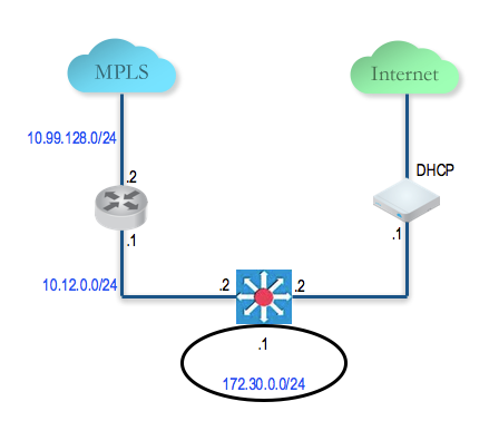
  12. Configure and Activate Hub 2: This step helps you to configure the "Steer by IP address" commonly used in one-arm Hub deployments. Below is an example of the wiring and IP address information. With one-arm deployment, the same tunnel source IP can be used to create overlay over different paths.
    Figure 4. Configure and Activate Hub 2
  13. Configure the Hub 2 Edge to Reach the Internet
    1. Connect a PC to the Edge and use the browser to point to http://192.168.2.1.
    2. Configure the Hub Edge to reach the Internet by configuring the first WAN interface, GE2.
  14. Add the Hub 2 Edge to the Orchestrator and Activate: In this step, you will create the second Hub Edge, called DC2.VCE.
    1. On the Orchestrator, go to Configure > Edges , select New Edge to add a new Edge.
    2. Go to Configure > Edges , select the Edge that you just created, then go to the Device tab to configure the same Interface and IP you configured in previous step.
      Important: Since we are deploying the Edge in one-arm mode (same physical interface but there will be multiple over tunnels from this interface), it is important to specify the WAN Overlay to be User Defined.
    3. At this point, you need to create the overlay. Under WAN Settings, additional Add User Defined WAN Overlay.
    4. Create an overlay across the public link. In our example, we will use the next-hop IP of 172.29.0.4 to reach the Internet through the firewall. The firewall is already configured to NAT the traffic to 209.116.155.31.
    5. Add the second overlay across the private network. In this example, we specify the next-hop router 172.29.0.1 and also specify the bandwidth since this is the MPLS leg and DC2-VCE is a Hub. Add a static route to the LAN side subnet, 172.30.128.0/24 through GE2.
    6. Activate the Edge. After the activation is successful, come back to the Device tab under the edge level configuration. Note the Public IP field is now populated. You should now see the links in the Monitor > Edges , under the Overview tab.
  15. Add the Hub 2 Edge to the Hub List in the Branch VPN Profile:
    1. Go to Configure > Profiles and select the profile Quick Start VPN.
    2. Go to the Device tab and add this new Edge to a list of Hubs.
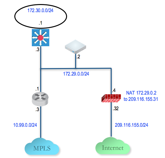
  16. Configure and Activate Hybrid Site-2: This step helps you create a Hybrid Site-1 – a hybrid site, which has the Edge behind CE router as well as Edge being the default router for the LAN. Below is an example of the wiring and IP address information for each hardware.
    Figure 5. Configure and Activate Hybrid Site-2

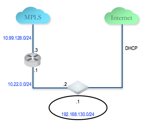
Connect a PC to the Edge LAN or Wi-Fi and use the browser to point to http://192.168.2.1.

For additional information on activation of Edges, see Activate Edges.

..