VeloCloud SD-WAN 7.0 - Administration Guide - Configure Dynamic Routing with OSPF or BGP
Print
Configure Dynamic Routing with OSPF or BGP
The system supports only eBGP when configuring BGP over IPsec.
The Edge learns routes from adjacent routers via OSPF and BGP, then transmits these routes to the Gateway/Controller. Acting as a route reflector, the Gateway/Controller distributes the learned routes to other Edges. The Overlay Flow Control (OFC) provides enterprise-wide route visibility and control, simplifying programming for both full and partial overlays.
The system supports Inbound/Outbound filters for OSPF neighbors, OE1/OE2 route types, and MD5 authentication. Routes that the Edge learns through OSPF automatically redistribute to the controller, whether hosted in the cloud or on-premises. Additionally, the administrator can apply BGP Inbound/Outbound filters and set them to Deny. Optionally, the administrator can add or modify BGP attributes—such as RFC 1998 community (https://datatracker.ietf.org/doc/html/rfc1998), MED, and local preference—to influence path selection.
Users can enable Open Shortest Path First (OSPF) only on a LAN interface as an active or passive interface. The Edge advertises only the prefix associated with that specific LAN switch port. To access full OSPF functionality, the user must use OSPF on routed interfaces.
Open Shortest Path First (OSPF) is an Interior Gateway Protocol (IGP) that operates within a single Autonomous System (AS).
Note: Configure OSPF only on the Global Segment.
OSPFv3 provides support for the following:
VeloCloud introduced support for OSPFv3 in the SD-WAN Edge for IPv6 underlay routing feature in addition to the existing BGPv6 support and supports the following:
Underlay IPv6 route learning
Redistribution of OSPFv3 routes into overlay/BGP and vice-versa
Support for Overlay Flow Control (OFC).
OSPFv3 has feature parity with OSPFv2 and does not support the following:
Point to Point (P2P)
BFDv6 with OSPFv3
OSPFv3 header therefore no MD5 authentication available
Note:
OSPFv2 supports only IPv4. OSPFv3 supports only IPv6 and is available starting with the 5.2 release.
Route Summarization is available starting with the 5.2 release.
To activate OSPF, perform the following steps:
In the SD-WAN service of the Enterprise portal, select Configure.
Note: Depending upon user's login permissions, users might need to select a Customer or Partner profile first, then select Configure.
Select Profiles to display the list of available Profiles.
Select a Profile from the list.
In the Routing and NAT section, select OSPF.
Under OSPF Areas, configure Redistribution Settings for OSPFv2/3, BGP Settings, and if applicable, Route Summarization.
Figure 1. OSPF Settings
Table 1. OSPF Settings - Options and Descriptions
Option
Description
Redistribution Settings
Default Route
Select an OSPF route type (O1 or O2) to use for the default route. The configuration uses None by default.
Advertise
Select either Always or Conditional. Selecting Always advertises the default route always. Selecting Conditional means to redistribute the default route only when the Edge learns it through overlay or underlay. Check the Overlay Prefixes option to use the Conditional default route.
Overlay Prefixes
If applicable, check Overlay Prefixes.
BGP Settings
BGP
To enable the injection of BGP routes into OSPF, select the BGP option. The system redistributes BGP routes into OSPF based on user's requirements; if applicable, enter or choose the configuration options as follows.
Set Metric
Enter the metric in Set Metric. It is the metric that OSPF puts in external LSAs generated from the redistributed routes. The default metric is 20.
Set Metric Type
From the Set Metric Type menu, select a metric type. It is either type E1 or type E2 OSPF External-LSA. The default type is E2.
In OSPF Areas, select +Add and configure the options. Add additional areas, if necessary, by selecting +Add. The fields in the following table cannot be overridden at the Edge level.
Table 2. OSPF Areas - Options and Descriptions
Option
Description
Area ID
Enter an OSPF Area ID.
Name
Enter a descriptive name.
Type
Normal Type selected by default as the only supported option.
Note: Activate OSPF at the Profile level first before configuring it on Edge interfaces.
If applicable, configure Route Summarization.
Note: The Route Summarization feature became available with the 5.2 release, for an overview and use case for this feature, see Route Summarization.
Locate the Route Summarization area.
Select +Add in the Route Summarization area to add a new row. Configure Route Summarization as described in the following table.
Figure 2. Route Summarization
Table 3. Route Summarization - Options and Descriptions
Option
Description
Subnet
Enter the IP subnet.
No Advertise
When setting No Advertise, all the external routes (Type-5) under this supernet summarize and do not advertise it. This means it effectively blocks the whole supernet from advertising to its peer.
Tag
Enter the router tag value from 1 to 4294967295.
Metric Type
Enter the Metric Type as E1 or E2.
Metric
Enter the advertised metric for this route from 0 to 16777215.
Add additional routes, if necessary, by selecting +Add. Use Clone or Delete to clone or delete a route summarization.
Select Save Changes.
Route Filters
There are two types of routing - Inbound and Outbound.
Inbound routing includes preferences that can be learned or ignored from OSPF and installed into the Overlay Flow Control.
Outbound Routing indicates which prefixes the system redistributes into OSPF.
Activate OSPF for Edges
Users can enable Open Shortest Path First (OSPF) on a LAN (routed or switched) or a WAN interface. Currently, the system does not provide an option to override the passive interface setting for OSPF on a VLAN interface, as the Edge only supports OSPF on a switched interface as a passive interface. The Edge only advertises the prefix associated with that LAN switch port. To get full OSPF functionality, users must use it on routed interfaces. After users configure the OSPF settings at the Profile level, all the Edges associated with the Profile inherit the OSPF configuration from the Profile. However, users cannot override the OSPF configuration settings at the Edge level.
Note: Edges running lower versions, 6.0 or lower, do not process OSPF configurations in non-global segments even though Orchestrator allows OSPF configuration at the Profile level.
Use the following steps to view OSPF configuration for a specific Edge device:
In the SD-WAN service of the Enterprise portal, select Configure > Edges.
Select Device next to an Edge, or select the link to an Edge and then select the Device tab.
Go to the Routing & NAT section and select OSPF.
In the OSPF section, users can view all the inherited OSPF configuration such as OSPF areas, Redistribution settings for OSPFv2/v3, BGP settings, and Route Summarization.
Figure 3. OSPF Settings
Configure BGP
Users can configure the BGP per segment for a Profile or an Edge, and configure BGP for Underlay Neighbors and Non SD-WAN Neighbors. VeloCloud supports 4-Byte ASN BGP as follows:
As the ASN of Edges
Peer to a neighbor with 4-Byte ASN
Accept 4-Byte ASNs in route advertisements
See the following sections for configuring BGP for Underlay Neighbors and Non SD-WAN Neighbors:
Configure BGP from Edge to Underlay Neighbors for Profiles
Users can configure the BGP per segment at the Profile level as well as at the Edge level. This section provides steps on how to configure BGP with Underlay Neighbors.
Arista VeloCloud SD-WAN supports 4-Byte ASN BGP. See Configure BGP, for additional information.
Route Summarization is new for the 5.2 release. For an overview, use case, and black hole routing details for Route Summarization, see section titled, Route Summarization. For configuration details, see the steps below.
To configure BGP:
In the SD-WAN service of the Enterprise portal, select the Configure tab.
From the left menu, select Profiles to display the Profile page.
Select a Profile from the list of available Profiles or add a Profile if necessary.
Go to the Routing & NAT section and select the arrow next to BGP to expand.
In the BGP area, toggle the radio button from Off to On.
Figure 4. BGP Settings
In the BGP area, enter the local Autonomous System Number (ASN) in the appropriate field.
Configure the BGP Settings.
Table 4. BGP Settings - Options and Descriptions
Option
Description
Router ID
Enter the global BGP router ID. If users do not specify any value, the ID is automatically assigned. If users have configured a loopback Interface for the Edge, the IP address of the loopback Interface will be assigned as the router ID.
Keep-Alive
Enter the keep-alive timer in seconds, which is the duration between the keep-alive messages sent to the peer. The range is from 0 to 65535 seconds. The default value is 60 seconds.
Hold Timer
Enter the hold timer in seconds. If users don't receive the keep-alive message within the specified time, the peer is down. The range is from 0 to 65535 seconds. The default value is 180 seconds.
Uplink Community
Enter the community string to treat as uplink routes. Uplink refers to link connected to the Provider Edge(PE). Inbound routes towards the Edge matching the specified community value is treated as Uplink routes. These routes are not owner of the Hub/Edge. Enter the value in number format ranging from 1 to 4294967295 or in AA:NN format.
Enable Graceful Restart checkbox
Note when selecting this checkbox: The local router does not support forwarding during the routing plane restart. This feature supports preserving forwarding and routing in case of peer restart.
Select +Add in the Filter List area to create one or more filters. These filters are applied to the neighbor to deny or change the attributes of the route. Users can use the same filter for multiple neighbors.
Figure 5. Filter List
Figure 6. Match Type
Figure 7. Action Set
In the appropriate text fields, set the rules for the filter, as described in the table below.
Table 5. Add Filter - Options and Descriptions
Option
Description
Filter Name
Enter a descriptive name for the BGP filter.
Match Type
Choose the type of the routes to match with the filter:
Prefix for IPv4 or IPv6- Choose to match with a prefix for IPv4 or IPv6 address and enter the corresponding prefix IP address in the Value field.
Community- Choose to match with a community and enter the community string in the Value field.
AS Path - Match routes using the user-provided AS path regular expression.
Metric- Match routes using the user-provided MED value.
Local preference-Match routes using the user-provided local preference value.
Match Value
Enter the subnet value.
Exact Match
It performs the filter action only when the Prosecutes match exactly with the specified prefix or community string. By default, this option is enabled.
Action Type
Select the action to perform when the routes match with the specified prefix or the community string. Users can either permit or deny the traffic.
Action Set
When the BGP routes match the specified criteria, users can set to route the traffic to a network based on the attributes of the path. Select one of the following options from the drop-down list:
None- The attributes of the matching routes remain the same.
Local Preference- It routes the matching traffic to the path with the specified local preference.
Community- It filters the matching routes by the specified community string. Users can also select Community Additive to enable the additive option, which appends the community value to existing communities.
Metric - It routes the matching traffic to the path with the specified metric value.
As-Path-Prepend- Allows pre-pending multiple entries of Autonomous System (AS) to a BGP
As-Path-Exclude - AS path exclude is a new set option, using which users can remove specific Autonomous System (AS) numbers from a route’s AS path. When users exclude ASNs, the system deletes all occurrences of the specified numbers, regardless of where they appear in the sequence.
AS path Regex match option
By using the AS Path Regex match type, administrators can filter BGP routes based on the autonomous systems they have traversed, applying a Permit or Deny action whenever a route's AS path matches the defined pattern. This approach enables the creation of sophisticated policies based on a route’s origin or transit history rather than just its prefix, allowing the system to accept routes from specific providers, block untrusted transit networks, or match defined ranges of ASNs.
Table 6. Supported AS Path Regex Characters
Character
Meaning / Use
Example
Matches Example AS Paths
0–9
Digits used in AS numbers
^65001$
65001
^
Start of AS path
^65001
65001 65002 65003
$
End of AS path
65001$
65003 65002 65001
_
AS boundary (start, end, space, comma, brace, or parentheses)
_65001_
65000 65001 65002
65001
|
Logical OR (alternation)
^(65001|65002)$
65001
65002
[]
Character class (any one character in set)
^6500[12]$
65001
65002
{}
Repeat count
[0-9]{5}
65000
()
Grouping (for OR or repetition)
(65001|65002) 65003
65002 65003 65004
(space)
AS separator
^65001 65002
65001 65002 65003
*
Zero or more repetitions
[0-9]*
65001
123
+
One or more repetitions
[0-9]+
65001
.
Any single character
6500.
65000–65009
?
Zero or one occurrence
6500[1-2]?
6500
65001
64002
-
Range indicator (inside [])
^65[0-9][0-9]$
6500–6599
\
Escape special characters (treat literally)
Usually matches confederations and AS_SET
_\{65200_
65100 {65200 65300}
_\(64512\)
65001 (64512) 65001
AS Path Exclude
AS path exclude is a new set option,using which users can remove specific Autonomous System (AS) numbers from a route’s AS path. When users exclude ASNs, the system deletes all occurrences of the specified numbers, regardless of where they appear in the sequence.
Example:
For instance, if a user provides input as "100 300" and a route's AS path is "100 200 300 400", the resulting AS path after filtering will be "200 400"
Select the + icon to add more matching rules for the filter. Repeat the procedure to create more BGP filters. The Filter List area displays the configured filters.
Note:
The maximum number of supported BGPv4 Match/Set rules is 512 (256 inbound, 256 outbound). Exceeding 512 total Match/Set rules may cause performance issues, resulting in disruptions to the enterprise network.
Older versions of Edge and their profiles show the new enhanced BGP filter options AS Path, AS-Path -Exclude, Metric and Local preference in the user interface, but these settings are not applied until upgraded to Edge version 7.0 or above.
Scroll down to Neighbors and select +Add.
Figure 8. Neighbors
Configure the following settings for the IPv4 addressing type:
Table 7. Neighbours - Options and Descriptions
Option
Description
Neighbor IP
Enter the IPv4 address of the BGP neighbor
ASN
Enter the ASN of the neighbor
Inbound Filter
Select an Inbound filer from the drop-down list
Outbound Filter
Select an Outbound filer from the drop-down list
Note: When overriding and configuring BGP neighbors at the Edge level, any Profile-level filters associated with the neighbors is removed when users switch the Edge from one profile to another. So at the Edge level, users must make sure to re-associate the filters with the BGP neighbors after switching the Edge profile.
Additional Options – Select the View all to configure the following additional settings:
Table 8. Additional Options and Descriptions
Option
Description
Max-hop
Enter the number of maximum hops to enable multi-hop for the BGP peers. The range is from 1 to 255 and the default value is 1.
Note: This field is available only for eBGP neighbors, when the local ASN and the neighboring ASN are different. With iBGP, when both ASNs are the same, multi-hop is inherent by default and this field is not configurable.
Local IP
Local IP address is the equivalent of a loopback IP address. Enter an IP address that the BGP neighborships can use as the source IP address forth outgoing packets. If users do not enter any value, it uses the IP address of the physical Interface as the source IP address.
Note: For eBGP, this field is available only when Max- hop count is more than 1. For iBGP, it is always available as iBGP is inherently multi-hop.
Uplink
Flag the neighbor type to Uplink. Select this option if users use the neighbor as the WAN overlay toward MPLS. The system uses this flag to determine if the site becomes a transit site (such as an SD-WAN Hub) by propagating routes learned over an SD-WAN overlay to a WAN link toward MPLS. If users want to establish the site as a transit site, users must also select the Overlay Prefix Over Uplink check box in the Advanced Settings area.
Allow AS
Select the checkbox to allow the BGP routes to receive and process even if the Edge detects its own ASN in the AS-Path.
Default Route
The Default Route adds a network statement in the BGP configuration to advertise the default route to the neighbor.
Enable BFD
Enables subscription to existing BFD session for the BGP neighbor.
Keep-Alive
Enter the keep-alive timer in seconds, which is the duration between the keep-alive messages sent to the peer. The range is from 0 to 65535 seconds. The default value is 60 seconds.
Hold Timer
Enter the hold timer in seconds. If users don't receive the keep-alive message within the specified time, the peer is down. The range is from 0 to 65535 seconds. The default value is 180 seconds.
Connect
Enter the time interval to try a new TCP connection with the peer if it detects the TCP session is not passive. The default value is 120 seconds.
MD5 Auth
Select the checkbox to enable BGP MD5 authentication. Administrators typically use this option in legacy or federal networks, where they commonly implement BGP MD5 as a security measure for BGP peering.
MD5 Password
Enter a password for MD5 authentication.
Note: Starting from the 4.5 release, the use of the special character < in the password is no longer supported. In cases where users have already used < in their passwords in previous releases, they must remove it to save any changes on the page.
Select the + to add more BGP neighbors. Over Multi-hop BGP, the system might learn routes that require recursive lookup. These routes have a next-hop IP which is not in a connected subnet, and do not have a valid exit Interface. In this case, the routes must have the next-hop IP resolved using another route in the routing table that has an exit Interface. When there is traffic for destination that needs these routes to look up, routes requiring recursive lookup resolves to a connected Next Hop IP address and Interface. Until the recursive resolution happens, the recursive routes point to an intermediate Interface.
For additional information about Multi-hop BGP Routes, see the Remote Diagnostic Tests on Edges section in the VeloCloud SD-WAN Troubleshooting Guide.
Navigate to Advanced Settings and select the down arrow to open the Advanced Settings section.
Figure 9. Advanced Settings
Configure the following advanced settings and globally apply them to all the BGP neighbors with IPv4 addresses.
Table 9. Advanced Settings - Options and Descriptions
Option
Description
Overlay Prefix
Select the check box to redistribute the prefixes learned from the overlay.
Turn off AS-Path carry over
The user should leave this option unchecked by default. Select the check box to turn off AS-PATH Carry Over. In certain topologies, turning off AS-PATH Carry Over will influence the outbound AS-PATH to make the L3 routers prefer a path towards an Edge or a Hub.
Warning: When users turn off AS-PATH Carry Over, users must tune their network carefully to avoid routing loops.
Connected Routes
Select to redistribute all the connected Interface subnets.
OSPF
Select the checkbox to enable OSPF redistribute into BGP.
Set Metric
When users enable OSPF, enter the BGP metric for the redistributed OSPF routes. The default value is 20.
Default Route
Select to redistribute the default route only when Edge learns the BGP routes through overlay or underlay. When users select the Default Route option, the Advertise option is available as Conditional.
Overlay Prefixes over Uplink
Select the checkbox to propagate routes learned from overlay to the neighbor with uplink flag.
Networks
Enter the network address in IPv6 format that BGP advertises to the peers. Select (+) to add more network addresses.
When users enable the Default Route option, the BGP routes are advertised based on the Default Route selection globally and per BGP neighbor.
Table 10. Default Route Advertising Options
Default Route Selection
Advertising Options
Global
Per BGP Neighbor
Yes
Yes
The per BGP neighbor configuration overrides the global configuration and hence the system always advertises the default route to the BGP peer.
Yes
No
BGP redistributes the default route to its neighbor only when the Edge learns an explicit default route through the overlay or underlay network.
No
Yes
The system advertises the default route to the BGP peer.
No
No
The system does not advertise the default route to the BGP peer.
Select the IPv6 tab to configure the BGP settings for IPv6 addresses. Enter a valid IPv6 address of the BGP neighbor in the Neighbor IP field.
The BGP peer for IPv6 supports the following address format:
Global unicast address (2001:CAFE:0:2::1)
Unique Local address (FD00::1234:BEFF:ACE:E0A4)
Configure the other settings as required.
Note: The Local IP address configuration is not available for IPv6 address type.
Select Advanced to configure the following advanced settings, which globally apply to all the BGP neighbors with IPv6 addresses.
Table 11. Advanced Options and Descriptions
Option
Description
Connected Routes
Select the checkbox to redistribute all the connected Interface subnets.
Default Route
Select the checkbox to redistribute the default route only when Edge learns the BGP routes through overlay or underlay. When users select the Default Route option, the Advertise option is available as Conditional.
Networks
Enter the network address in IPv6 format that BGP will be advertising to the peers. Select the Plus (+) Icon to add more network addresses.
The Route Summarization feature is available in the 5.2 release, for an overview and use case of this functionality, see Route Summarization. For configuration details, follow the Steps 19 to 24.
Select +Add in the Route Summarization area. It adds a new row to the Route Summarization area.
Figure 10. Route Summarization
Under the Subnet column, enter the network range that users want to summarize in the A.B.C.D/M format and the IP subnet.
Under the AS Set column, select Yes if applicable.
Under the Summary Only column, select the Yes checkbox to allow only the summarized route to be sent.
Add additional routes, if necessary, by selecting +Add. To Clone or Delete a Route Summarization, use the appropriate buttons, located next to +Add. The BGP Settings section displays the BGP configuration settings.
Select Save Changes when complete to save the configuration.
Note: When users configure BGP settings for a profile, the configuration settings are automatically applied to the SD-WAN Edges associated with the profile.
Configure BGP from Edge to Underlay Neighbors for Edges
Users can override the inherited Profile settings at the Edge level when configuring BGP from the Edge to Underlay Neighbors.
If required, users can override the configuration for a specific Edge as follows:
In the SD-WAN service of the Enterprise portal, select Configure > Edges. The Edges page displays the configured Edges.
Select on an Edge or select View in the Device column of the Edge.
Go to the Routing & NAT section and select the arrow next to BGP to expand.
The BGP settings configured for the associated Profile are displayed. If required, users can select Override and modify the BGP Settings.
Note: Overriding and configuring BGP neighbors at the Edge level removes any Profile-level filters associated with the neighbors when users switch the Edge from one profile to another. At the Edge level, users must re-associate the filters with the BGP neighbors after switching the Edge profile.
In addition to the BGP Settings configured for a Profile, users can select an Edge Interface configured in the segment as the source Interface for BGP. For the IPv4 address type, users can select only the Loopback Interface as Source Interfacee, and for the IPv6 address type, users can select any Edge Interface as the Source Interface. This field becomes available:
Only when users choose to override the BGP Settings at the Edge level.
For eBGP, only when Max-Hop count is greater than 1. For iBGP, it is always available as iBGP is inherently multi-hop.
Important:
Users cannot select an Edge Interface if users have already configured a local IP address in the Local IP field.
Users cannot configure a local IP address if users have selected an Edge Interface in the Source Interface list.
Select Save Changes to save the modified configuration.
BGP over IPsec from Edge to Non SD-WAN Neighbors Overview
The Non SD-WAN BGP Neighbors configuration does not apply to the Profile level. Users can configure the NSD Neighbors only at the Edge level.
BGP establishes the BGP neighborship over the IPsec tunnels to the Non SD-WAN Sites. Direct IPsec tunnels establish a secure communication between the SD-WAN Edge and the Non SD-WAN Destination (NSD). In previous releases, VeloCloud supported NSD tunnels from the SD-WAN Edge, allowing the addition of NVS static routes. In the 4.3 release, this functionality extends support to BGP over IPsec to the NSD endpoint for a route-based VPN.
VeloCloud SD-WAN supports 4-Byte ASN BGP. See Configure BGP for more information.
Note: The Azure vWAN Automation from Edge feature does not support BGP over IPsec because it only supports static routes when automating connectivity from an Edge to an Azure vWAN.
Each Azure VPN gateway allocates one set of public Virtual Public IPs (VIP) for a branch Edge to form IPsec tunnels. Similarly, Azure also allocates one internal private subnet and assigns one internal IP per VIP. This internal tunnel-ip (peer tunnel-ip) creates BGP peering with the Azure Gateway.
Azure has a restriction that the BGP peer IP (Edge's local tunnel IP) cannot be on the same subnet as the Edge or on the 169.x.x.x subnet, and therefore, VeloCloud supports multi-hop BGP on the Edge. In BGP terminology, the local tunnel-ip maps to the BGP source address, and the peer tunnel-ip maps to the neighbor or peer address. The configuration must form a mesh of BGP connections- one per NSD tunnel so that the return traffic from the NVS can be load-balanced (flow-based) on the Azure Gateway side. The example network diagram for the physical Edge displays two public WAN links and therefore consists of four tunnels to an Azure Gateway. Each tunnel is uniquely associated with one BGP connection, identified by the local tunnel_ip and the remote peer tunnel_ip. On the Virtual Edge, the configuration has one public WAN link and a maximum of two tunnels and two BGP sessions to the Azure Gateway. Each Azure VPN gateway allocates one set of public Virtual Public IPs (VIP) for a branch Edge to form IPsec tunnels. Similarly, Azure also allocates one internal private subnet and assigns one internal IP per VIP. This internal tunnel-ip (peer tunnel-ip) creates BGP peering with the Azure Gateway.
Figure 11. BGP over IPsec from Edge to Non SD-WAN Neighbors Overview
Note: When an SD-WAN Edge connects to the same Azure endpoint using multiple WAN links, a maximum of two NSD-BGP neighbors can be configured, since the remote end has only two public IPs and two NSD-BGP peer IPs. Users can configure both NSD-BGP neighbors on the same link (primary/secondary tunnel) or on different links if users attempt to configure more than two NSD-BGP neighbors and configure the same NSD-BGP peer-ip on more than one tunnel with the last configured BGP nbr-ip over local-ip on the SD-WAN Edge and Free Range Routing (FRR).
Use Case 1- BGP Over IPsec from an Edge to an Azure VPN
Unlike Azure, AWS VPN Gateway allocates one set of public VIPs per link to a branch Edge. The total set of public IPs allocated to a branch Edge from an AWS Gateway equals the number of Edge public WAN links that connect to the AWS VPN Gateway. Similarly, a /30 internal/private subnet allocates a per-tunnel address for BGP peering on that tunnel. The user can manually override these IPs in the AWS Gateway configuration to ensure uniqueness across different availability zones.
Similar to the Azure use-case, the Edge forms a mesh of BGP connections- one per tunnel to the AWS gateway. It allows load-balancing of the return traffic from the AWS VPN Gateway- design on the AWS side. In the example diagram, for the physical Edge, the AWS Gateway allocates one set of public IPs and one set of tunnel IPs (/30) for each Edge WAN link, for a total of 4 tunnels. It terminates in different public IPs on the AWS Gateway and four BGP connections.
Figure 12. BGP Over IPsec from an Edge to an Azure VPN
Use Case 2- An Edge Connecting to Both AWS and Azure VPN Gateways (Hybrid Cloud)
An Edge at a single branch can connect to both an Azure Gateway and an AWS Gateway to provide redundancy or to reach specific workloads and applications hosted across different cloud providers. Regardless of a specific use case, the Edge always establishes one BGP session per tunnel and propagates routes between the SD-WAN and the IaaS environment. The following diagram shows an example of a branch Edge connected to both the Azure and AWS clouds.
Figure 13. Edge Connecting to Both AWS and Azure VPN Gateways (Hybrid Cloud)
Use Case 3- A Hub Cluster Connecting to Azure and AWS Transit Gateways
Hub cluster members can form IPsec tunnels to the Azure and AWS transit Gateways and leverage them as Layer 3 for routing traffic between different VPCs. Without the native BGP over IPsec functionality on the Hub, the Hub must connect to an L3 router via native BGP, and the L3 router forms a mesh of BGP over IPsec tunnels among different VPCs. The L3 router serves as a transit endpoint between different VPCs.
Use Case-1 uses a Hub as a transit node between VPCs in different Availability Zones (AZs), enabling communication between VPCs. Use Case-2 connects all Hubs in the cluster directly to a cloud transit gateway and can use the cloud gateway as a PE (L3) router for route distribution between cluster members. In both use cases, without support for BGP over IPsec on the Hub, the Hub connects to an L3 router like a CSR using native BGP and peers with a transit and VPC gateway using BGP over IPsec.
Figure 14. Hub Cluster Connecting to Azure and AWS Transit Gateways
Use Case 4- Supporting Transit Functionality in Cloud Providers without Native Support
Some cloud providers, such as Google Cloud and AliCloud, do not have native support for transit functionality (no transit Gateways) and, with BGP over IPsec, can rely on SD-WAN Edge/Hub deployed in the cloud to achieve transit between different VPCs/VNETs. Without BGP over IPsec support, users must use an L3 router to achieve the transit functionality.
Note: Before the 4.3 release, for customers with reachability to the same NVS-Static destination via an NVS-From-Gateway and an NVS-From-Edge, traffic from other branch SD-WAN Edges prefers the path through an NVS-Gateway. When users upgrade their network to the 4.3 release or later, this traffic path from other branch- SD-WAN Edges prefers the path through the NVS-Edge. Therefore, users must update the NVS-Static-Destination metric for the NSD-Edge and NSD-Gateway based on the traffic path preference.
Requires a Local IP address from the Edge to configure BGP with NSD Neighbors.
Use the following steps to enable BGP with Non SD-WAN neighbors:
In the SD-WAN service of the Enterprise portal, select Configure.
From the left menu, select Edges. The Edges page displays.
Select an Edge from the list of available Edges.
Go to the Routing & NAT section in the UI and select the arrow next to BGP.
In the BGP area, select Overrideand toggle the radio button from Off to On.
Figure 15. BGP Settings
In BGP Editor, configure the following settings:
Enter the local Autonomous System Number (ASN) and then configure the following in the BGP Settings section.
Configure the BGP Settings:
Table 12. BGP Settings - Options and Descriptions
Option
Description
Router ID
Enter the global BGP router ID. If users do not specify any value, it automatically assigns the ID. When users configure a loopback Interface for the Edge, the IP address of the loopback Interface is assigned as the router ID.
Keep Alive
Enter the keep alive timer in seconds, which is the duration between the keep alive messages that are sent to the peer. The range is from 0 to 65535 seconds. The default value is 60 seconds.
Hold Timer
Enter the hold timer in seconds. When the system does not receive the keep alive message for the specified time, the peer is considered as down. The range is from 0 to 65535 seconds. The default value is 180 seconds.
Uplink Community
Enter the community string to treat as uplink routes. Uplink refers to link connected to the Provider Edge(PE). Inbound routes towards the Edge matching the specified community value will treat as Uplink routes. The Hub/Edge is not the owner for these routes. Enter the value in number format ranging from 1 to 4294967295 or in AA:NN format.
Enable Graceful Restart
When enabling graceful restart- The local router does not support forwarding during the routing plane restart. This feature supports preserving forwarding and routing in case of peer restart.
Select +Add in the Filter List area to create one or more filters. Apply these filters to the neighbor and deny or change the attributes of the route. The user can apply the same filter to multiple neighbors.
Figure 16. Filter List
In the appropriate fields, set the rules for the filter:
Table 13. Filter List - Options and Descriptions
Option
Description
Filter Name
Enter a descriptive name for the BGP filter.
Match Type and Value
Choose the type of the routes to match with the filter:
Prefix for IPv4 or IPv6- Match with a prefix for IPv4 or IPv6 address and enter the corresponding prefix IP address in the Value field.
Community- Match with a community and enter the community string in the Value field.
Exact Match
The system performs the filter action only when the BGP routes match the specified prefix or community string exactly. The system enables this option by default.
Action Type
Choose the action the system performs when the BGP routes match the specified prefix or community string. Users can either permit or deny the traffic.
Action Set
When the BGP routes match the specified criteria, users can set to route the traffic to a network based on the attributes of the path. Select one of the following options from the drop-down list:
None- The attributes of the matching routes remain the same.
Local Preference- The system routes matching traffic to the path associated with the specified local preference.
Community- The specified community string filters the matching routes. Users can also select Community Additive to enable the additive option, which appends the community value to existing communities.
Metric- The system routes matching traffic to the path associated with the specified metric value.
AS-Path-Prepend- Allows pre-pending multiple entries of Autonomous System (AS) to a BGP route.
To add more matching rules to the filter, select the Plus (+) icon.
Select OK to create the filter. The configured filters display in BGP Editor.
Configure Underlay Neighbors for IPv4 and IPv6 addresses, as required. For more information, see Configure BGP from Edge to Underlay Neighbors with New Orchestrator UI.
Note: The maximum number of supported BGPv4 Match/Set rules is 512 (256 inbound, 256 outbound). Exceeding 512 total Match/Set rules may cause performance issues, resulting in disruptions to the enterprise network.
In the NSD Neighbors section, configure the following settings:
Table 14. NSD Neighbors - Options and Descriptions
Option
Description
NSD Name
Select the NSD Name from the list. The NSDs already configured in the Branch to Non SD-WAN Destination via Edge area of the Orchestrator display in the list.
Link Name
Select the name of the WAN link associated with the NSD neighbor.
Tunnel Type
Choose the tunnel type of the Peer as Primary or Secondary.
Neighbor IP
Enter the IP address of the NSD neighbor.
ASN
Enter the ASN for the NSD neighbor.
Inbound Filter
Select an Inbound filter from the list.
Outbound Filter
Select an Outbound filter from the list.
Additional Options– Select View All to configure the following additional settings:
Uplink
Use this option to flag the neighbor type as Uplink. Select this flag if users use the neighbor as the WAN overlay toward MPLS. The system uses this flag to determine if the site becomes a transit site (such as an SD-WAN Hub) by propagating routes learned over an SD-WAN overlay to a WAN link toward MPLS. If users want to establish the site as a transit site, select the Overlay Prefix Over Uplink check box in the Advanced Settings.
Local IP
Local IP is mandatory for configuring Non SD-WAN Neighbors. A local IP address is the equivalent of a loopback IP address. Enter an IP address that the BGP neighborships can select as the source IP address for the outgoing packets.
Max-hop
Enter the maximum number of hops to enable multi-hop for the BGP peers. For the 5.1 release and later, the range is from 2 to 255 and the default value is 2.
Note: When upgrading to the 5.1 release, any max-hop value of 1 is automatically updated to 2.
Note: This field is available only for eBGP neighbors when the local and neighboring ASNs differ. With iBGP, when both ASNs match, the system deactivates multi-hop by default and does not allow the user to configure this field.
Allow AS
Select the checkbox to allow the BGP routes to be received and processed even if the Edge detects its own ASN in the AS-Path.
Default Route
The Default Route adds a network statement in the BGP configuration to advertise the default route to the neighbor.
Enable BFD
Enables subscription to the existing BFD session for the BGP neighbor.
Note: The system does not support single-hop BFD sessions for BGP over IPsec with NSD Neighbors; however, the Edge supports multi-hop BFD for these configurations.
When setting up NSD-BGP sessions, users must provide a Local IP. The SD-WAN Edge treats only the directly connected Interface IPs as single-hop BFD sessions.
Keep Alive
Enter the keep-alive timer in seconds, the interval between keep-alive messages sent to the peer. The range is from 0 to 65535 seconds. The default value is 60 seconds.
Hold Timer
Enter the hold timer in seconds. If users don't receive the keep-alive message within the specified time, the peer is down. The range is from 0 to 65535 seconds. The default value is 180 seconds.
Connect
Enter the time interval to try a new TCP connection with the peer if it detects that the TCP session is not passive. The default value is 120 seconds.
MD5 Auth
Select the checkbox to enable BGP MD5 authentication. Administrators typically use this option in legacy or federal networks, where they commonly implement BGP MD5 as a security measure for BGP peering.
MD5 Password
Enter a password for MD5 authentication.
Note: Starting from the 4.5 release, the use of the special character < in the password is no longer supported. In cases where users have already used < in their passwords in previous releases, they must remove it to save any changes on the page.
Note: When the system learns routes over Multi-hop BGP, it may require a recursive lookup to process them. These routes contain a next-hop IP that does not reside in a connected subnet and lacks a valid exit interface.
In this scenario, the system must resolve the next-hop IP by using another route in the routing table that provides a valid exit interface. When traffic arrives for a destination requiring these routes, the system resolves the recursive route to a connected Next Hop IP address and interface. Until this recursive resolution completes, the recursive routes point to an intermediate interface. For more information about Multi-hop BGP Routes, see the Remote Diagnostic Tests on Edges section in the Arista VeloCloud SD-WAN Troubleshooting Guide.
Select Advanced to configure the following settings:
Note: VeloCloud shares Advanced Settings across both the underlay BGP neighbors and NSD BGP neighbors.
Table 15. Advanced Settings - Options and Descriptions
Option
Description
Overlay Prefix
Select the check box to redistribute the prefixes learned from the overlay.
Turn off AS-Path carry over
The user should leave this option unchecked by default. Select the check box to turn off AS-PATH Carry Over. In certain topologies, turning off AS-PATH Carry Over will influence the outbound AS-PATH to make the L3 routers prefer a path towards an Edge or a Hub.
Warning: When users turn off AS-PATH Carry Over, users must tune their network carefully to avoid routing loops.
Connected Routes
Select to redistribute all the connected Interface subnets.
OSPF
Select the checkbox to enable OSPF redistribute into BGP.
Set Metric
When users enable OSPF, enter the BGP metric for the redistributed OSPF routes. The default value is 20.
Default Route
Select to redistribute the default route only when Edge learns the BGP routes through overlay or underlay. When users select the Default Route option, the Advertise option is available as Conditional.
Overlay Prefixes over Uplink
Select the checkbox to propagate routes learned from overlay to the neighbor with uplink flag.
Networks
Enter the network address in IPv6 format that BGP advertises to the peers. Select (+) to add more network addresses.
When users enable the Default Route option, the system advertises BGP routes based on the Default Route selection both globally and per individual BGP neighbor:
Table 16. Default Route Selection
Global
Per BGP Neighbor
Advertising Options
Yes
Yes
The per BGP neighbor configuration overrides the global configuration and hence default route is always advertised to the BGP peer.
Yes
No
BGP redistributes the default route to its neighbor only when the Edge learns an explicit default route through the overlay or underlay network.
No
Yes
Default route is always advertised to the BGP peer.
No
No
The default route is not advertised to the BGP peer.
Select OK to save the configured filters and NSD Neighbors.
The BGP Settings section displays the configured settings.
Route Summarization
The Route Summarization feature is available in the 5.2 release, for an overview and use case of this functionality, see Route Summarization. For configuration details, follow the steps below.
Select +Add in the Route Summarization to add a new row to the Route Summarization table.
Figure 17. Route Summarization
Under the Subnet column, enter the network range that users want to summarize in the A.B.C.D/M format and the IP subnet.
Under the AS Set column, select Yes if applicable.
Under the Summary Only column, select Yes to allow only the summarized route to be sent.
Add additional routes, if necessary, by selecting +Add. To Clone or Delete a route summarization, use the appropriate buttons, located next to +Add.
The BGP Settings section displays the BGP configuration settings.
Select Save Changes when complete to save the configuration.
Configure BGP Over IPsec from Gateways
The system supports only eBGP when configuring BGP over IPsec..
Users can configure BGP Settings for Gateways over IPsec tunnels.
Note: Arista recommends using eBGP between the SD-WAN Gateway and NSD sites. If users use iBGP, the system cannot apply local preference via an outbound filter. In that scenario, users must choose either metric or AS path prepend options to achieve the desired routing.
VeloCloud allows Enterprise users to define and configure a Non SD-WAN Destination instance in order to establish a secure IPsec tunnel to a Non SD-WAN Destination through an SD-WAN Gateway.
Note:
For the 5.2 release, when multiple NSDs are configured for the same segment, the same set of summary route configurations must be present across all NSDs.
The Azure vWAN Automation from Gateway feature is not compatible with BGP over IPsec. It only supports static routes when automating connectivity from a Gateway to an Azure vWAN.
Important: Distributed Cost Calculation (DCC) is mandatory for ECMP to work properly.
Configure one of the following types of Gateways:
Create a Non SD-WAN Destination via Gateway for one of the following sites:
Associate the Non SD-WAN Destination to a Profile. See Configure a Tunnel Between a Branch and a Non SD-WAN Destinations via Gateway.
Note: Arista recommends enabling Distributed Cost Calculation to ensure optimal performance and scaling when utilizing BGP over IPsec via the Gateway. The system supports Distributed Cost Calculation starting with Release 3.4.0. For additional information on Distributed Cost Calculation, refer to the Configure Distributed Cost Calculation section in the VeloCloud SD-WAN Operator Guide.
Go to Configure > Network Services and then under Non SD-WAN Destinations, expand Non SD-WAN Destinations via Gateway.
Note: The New NSD via Gateway option appears only when there are no items in the table. Follow Step 2 and Step 3 to create a new Non SD-WAN Destination.
Figure 18. Non SD-WAN Destinations
Select +New to create a new Non SD-WAN Destination.
Figure 19. New Non SD-WAN Destinations via Gateway
In Non SD-WAN Destinations via Gateway, configure the following fields:
Table 17. Non SD-WAN Destinations via Gateway - Options and Descriptions
Option
Description
Name
Enter a name for the Non SD-WAN Destination in the text box.
Type
Select an IPsec tunnel type from the menu.
Tunnel Mode
Active/ Hot-Standby mode supports to set up a maximum of 2 tunnel endpoints or Gateways.
Active/Active mode supports to set up a maximum of 4 tunnel endpoints or Gateways. All Active tunnels can send and receive traffic through ECMP.
VPN Gateway 1
Enter a valid IP address.
VPN Gateway 2
Enter an optional valid IP address.
Select Create to add the new destination.
Figure 20. Non SD-WAN Destinations via Gateway
In the Non SD-WAN Destinations via Gateway area, slide the grey bar to the far right to the BGP column.
Select the Edit link under the BGP column.
If the Edit link does not display under the BGP column, see the section Configure a Tunnel Between a Branch and a Non SD-WAN Destinations via Edge to enable an Edge to Non SD-WAN via Gateway.
After selecting the Edit link under the BGP column, the Edit BGP dialog displays.
Toggle the BGP Activated radio button to the right to turn it green.
Select +Add to create one or more filters. These filters are applied to the neighbor to deny or change the attributes of the route. The same filter can be used for multiple neighbors.
Configure the options in the Filter List area:
Figure 21. Match Type
Figure 22. Action Set
Table 18. Filter Rules - Options and Descriptions
Option
Description
Filter Name
Enter a descriptive name for the BGP filter.
Match Type
Choose the type of the routes to match with the filter:
Prefix for IPv4 or IPv6- Choose to match with a prefix for IPv4 or IPv6 address and enter the corresponding prefix IP address in the Value field.
Community- Select to match with a community and enter the community string in the Value field.
AS Path - Match routes using the user-provided AS path regular expression.
Metric- Match routes using the user-provided MED value.
Local preference- Match routes using the user-provided local preference value.
Match Value
Enter the subnet value.
Exact Match
It performs filter action only when the BGP routes match exactly with the specified prefix or community string. By default, this option is enabled.
Action Type
Choose the action to perform when the BGP routes match with the specified prefix or the community string. Users can either permit or deny the traffic.
Action Set
When the BGP routes match the specified criteria, users can set to route the traffic to a network based on the attributes of the path. Select one of the following options from the drop-down list:
None- The attributes of the matching routes remain the same.
Local Preference- It routes matching traffic to the path associated with the specified local preference.
Community- It filters the matching routes by the specified community string. Users can also select Community Additive to enable the additive option, which appends the community value to existing communities.
Metric- It routes matching traffic to the path associated with the specified metric value.
AS-Path-Prepend- Allows pre-pending multiple entries of Autonomous System (AS) to a BGP route.
As-Path-Exclude - AS path exclude is a new set option, using which users can remove specific Autonomous System (AS) numbers from a route’s AS path. When users exclude ASNs, the system deletes all occurrences of the specified numbers, regardless of where they appear in the sequence.
AS path Regex match option
By using the AS Path Regex match type, administrators can filter BGP routes based on the autonomous systems they have traversed, applying a Permit or Deny action whenever a route's AS path matches the defined pattern. This approach enables the creation of sophisticated policies based on a route’s origin or transit history rather than just its prefix, allowing the system to accept routes from specific providers, block untrusted transit networks, or match defined ranges of ASNs.
Table 19. Supported AS Path Regex Characters:
Character
Meaning / Use
Example
Matches Example AS Paths
0–9
Digits used in AS numbers
^65001$
65001
^
Start of AS path
^65001
65001 65002 65003
$
End of AS path
65001$
65003 65002 65001
_
AS boundary (start, end, space, comma, brace, or parentheses)
_65001_
65000 65001 65002
65001
|
Logical OR (alternation)
^(65001|65002)$
65001
65002
[]
Character class (any one character in set)
^6500[12]$
65001
65002
{}
Repeat count
[0-9]{5}
65000
()
Grouping (for OR or repetition)
(65001|65002) 65003
65002 65003 65004
(space)
AS separator
^65001 65002
65001 65002 65003
*
Zero or more repetitions
[0-9]*
65001
123
+
One or more repetitions
[0-9]+
65001
.
Any single character
6500.
65000–65009
?
Zero or one occurrence
6500[1-2]?
6500
65001
64002
-
Range indicator (inside [])
^65[0-9][0-9]$
6500–6599
\
Escape special characters (treat literally)
Usually matches confederations and AS_SET
_\{65200_
65100 {65200 65300}
_\(64512\)
65001 (64512) 65001
AS Path Exclude
AS path exclude is a new set option, using which users can remove specific Autonomous System (AS) numbers from a route’s AS path. When users exclude ASNs, the system deletes all occurrences of the specified numbers, regardless of where they appear in the sequence.
Example:
For instance, if a user provides input as "100 300" and a route's AS path is "100 200 300 400", the resulting AS path after filtering will be "200 400"
Select (+) to add more matching rules for the filter. Repeat the procedure to create more filters.
Figure 23. Filter List
Figure 24. Edit BGP
Note: The system assigns these BGP neighbors to their respective tunnels exclusively to establish neighborship and facilitate subsequent control exchanges. This configuration ensures that all such communication occurs solely over the designated tunnels.
In the BGP Editor window, configure the BGP settings for the Primary and Secondary Gateways.
Note: The Secondary Gateway option is available only if users have configured a secondary Gateway for the corresponding Non SD-WAN Destination.
Note: In a customer deployment where users configure a Non VeloCloud SD-WAN Destination (NSD) via Gateway with redundant tunnels, the system may exhibit specific path preferences. If the Primary and Secondary Gateways advertise a prefix with an equal AS path to the Primary and Secondary NSD tunnels, the Primary NSD tunnel prefers the redundant Gateway path over the Primary Gateway.
In the Primary Cloud Gateway section, enter the local ASN and the Router ID.
Scroll down to the Neighbors area and select +Add.
Configure the following settings in the Neighbors area:
Figure 25. Neighbors
Table 20. Neighbors - Options and Descriptions
Option
Description
Local ASN
Enter the local Autonomous System Number (ASN)
Router ID
Enter the BGP Router ID.
Neighbor IP
Enter the IP address of the NSD neighbor.
ASN
Enter the ASN for the NSD neighbor.
Inbound Filter
Select an Inbound filter from the list.
Outbound Filter
Select an Outbound filter from the list.
Additional Options – Select View All to configure the following additional settings:
Local IP
Local IP is mandatory for configuring Non SD-WAN Neighbors. Local IP address is the equivalent of a loopback IP address. Enter an IP address that the BGP neighborships can use as the source IP address for the outgoing packets.
Max-hop
Enter the number of maximum hops to enable multi-hop for the BGP peers. For the 5.1 release and later, the range is from 2 to 255 and the default value is 2.
Note: When upgrading to the 5.1 release, any max-hop value of 1 automatically updates to a max-hop value of 2.
Note: This field is available only for eBGP neighbors, when the local ASN and the neighboring ASN are different. With iBGP, when both ASNs are the same, it deactivates the multi-hop by default and this field is not configurable.
Allow AS
Select the check box to allow the Edge to receive and process BGP routes even if it detects its own ASN in the AS-Path.
Default Route
The Default Route adds a network statement in the BGP configuration to advertise the default route to the neighbor.
Enable BFD
Enables subscription to existing BFD session for the BGP neighbor.
Note: The system does not support single-hop BFD sessions for BGP over IPsec with NSD Neighbors; however, the Edge supports multi-hop BFD for these configurations. When setting up NSD-BGP sessions, users must provide a Local IP. The SD-WAN Edge treats only the directly connected Interface IPs as single-hop BFD sessions.
Keep Alive
Enter the keep alive timer in seconds, which is the duration between the keep alive messages that are sent to the peer. The range is from 0 to 65535 seconds. The default value is 60 seconds.
Hold Timer
Enter the hold timer in seconds. If the Edge does not receive a Keep Alive message within the specified time, the system considers the peer to be down. The range is from 0 to 65535 seconds. The default value is 180 seconds.
Connect
Enter the time interval to try a new TCP connection with the peer if it detects the TCP session is not passive. The default value is 120 seconds.
MD5 Auth
Select the check box to enable BGP MD5 authentication. Users typically use this option in legacy or federal networks to secure BGP peering.
MD5 Password
Enter a password for MD5 authentication.
Note: Starting from the 4.5 release, it does not support special character < in the password. In cases where users have already used < in their passwords in previous releases, they must remove it to save any changes on the page.
The Neighbors area displays the configured Neighbors
Figure 26. Edit BGP
Note: In multi-hop BGP, the system might learn routes that require recursive lookups. These routes have a next-hop IP address that is not in a connected subnet and do not have a valid exit Interface. In this case, the routes must have the next-hop IP resolved using another route in the routing table that has an exit Interface. When there is traffic for a destination that needs these routes to be looked up, routes requiring recursive lookup will get resolved to a connected Next Hop IP address and Interface. Until the recursive resolution happens, the recursive routes point to an intermediate Interface. For additional information about Multi-hop BGP Routes, see the Remote Diagnostic Tests on Edges section in the VeloCloud SD-WAN Troubleshooting Guide.
Select Save Changes.
Route Summarization
The Route Summarization feature is available in the 5.2 release, for an overview and use case of this functionality, see Route Summarization. For configuration details, follow the steps below.
Scroll down to the Route Summarization area.
Select +Add in the Route Summarization to add a new row to the Route Summarization table. Configure route summarization, as described in the table below.
Figure 27. Route Summarization
Table 21. Route Summarization - Options and Descriptions
Option
Description
Filter Name
Enter a descriptive name for the BGP filter.
Subnet
Enter the IP subnet.
AS Set
Generate AS set path information from the summarized routes (while advertising the summary route to the peer). Under the AS Set column, select Yes if applicable.
Summary Only
Select Yes to allow only the summarized route to be sent.
Add additional routes, if necessary, by selecting +Add. To Clone or Delete a route summarization, use the appropriate buttons, located next to +Add.
The BGP Settings section displays the BGP configuration settings.
Select Save Changes when complete to save the configuration.
Note:
Only Gateways running version 6.0 or later have an option to configure up to 4 tunnels per VPN type. In addition, those tunnels intended to be a Non SD-WAN gateway can operate in either AA or A-HS mode to achieve the user's load-sharing/balancing preferences.
For gateways running a version earlier than 6.0, the system interprets all active-active configurations as active-hotstandby. In this scenario, the system designates Tunnel 1 as active and Tunnel 2 as hot-standby.
Monitor BGP Sessions
Users can monitor the BGP sessions on Edges and Gateways.
Refer to the following sections to monitor the BGP sessions:
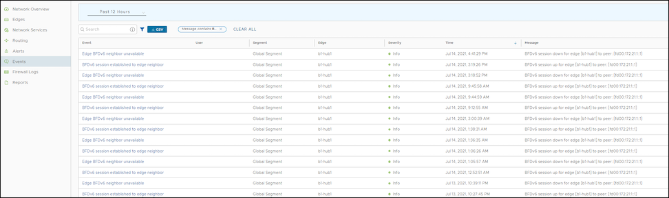
Users can view the events related to the BGP sessions.
In the SD-WAN service of the Enterprise Portal, select Monitor > Events.
To view the events related to BGP, users can use the filter option. Select Filter next to Search and opt to filter the details by different categories.
Figure 28. Monitoring BGP Events
Review the following BGP events:
BGP session established to Gateway neighbor
BGP session established to Edge neighbor
BGPv6 session established to Edge neighbor
Unavailable BGP neighbor
Unavailable BGPv6 neighbor
Unavailable Gateway BGP neighbor
Troubleshoot BGP Sessions
Users can run Remote Diagnostics tests to view the logs of the BGP sessions and use the log information for troubleshooting purposes.
Use the following steps to run tests for troubleshooting BGP:
In the SD-WAN service of the Enterprise portal, select Diagnostics > Remote Diagnostics.
The Remote Diagnostics page displays all the active Edges.
Select the Edge that users want to troubleshoot. The Edge enters live mode and displays all the possible Remote Diagnostics tests than users can run on the Edge.
For troubleshooting BGP sessions, scroll to the following sections and run the tests:
Troubleshoot BGP- List BGP Redistributed Routes – Run this test to view routes redistributed to BGP neighbors.
Troubleshoot BGP- List BGP Routes – Run this test to view the BGP routes from neighbors. Users can enter IPv4 or IPv6 prefix to view specific BGP routes or leave the prefix empty to view all the BGP routes.
Troubleshoot BGP- List Routes per Prefix – Run this test to view all the Overlay and Underlay routes for a specific IPv4 or IPv6 prefix and the related details
Troubleshoot BGP- Show BGP Neighbor Advertised Routes – Run this test to view the BGP routes advertised to a neighbor.
Troubleshoot BGP- Show BGP Neighbor Learned Routes – Run this test to view all the accepted BGP routes learned from a neighbor after filters.
Troubleshoot BGP- Show BGP Neighbor Received Routes – Run this test to view all the BGP routes learned from a neighbor before filters.
Troubleshoot BGP- Show BGP Neighbor Details – Run this test to view the details of BGP neighbor.
Troubleshoot BGP- Show BGP Routes per Prefix – Run this test to view all the BGP routes and their attributes for the specified prefix.
Troubleshoot BGP- Show BGP Summary – Run this test to view the existing BGP neighbor and received routes.
Troubleshoot BGP- Show BGP Table – Run this test to view the BGP table.
Troubleshoot BGPv6- Show BGPv6 Neighbor Advertised Routes – Run this test to view the BGPv6 routes advertised to a neighbor.
Troubleshoot BGPv6- Show BGPv6 Neighbor Learned Routes – Run this test to view all the accepted BGPv6 routes learned from a neighbor after filters.
Troubleshoot BGPv6- Show BGPv6 Neighbor Received Routes – Run this test to view all the BGPv6 routes received from a neighbor before filters.
Troubleshoot BGPv6- Show BGPv6 Neighbor Details – Run this test to view the details of BGPv6 neighbor.
Troubleshoot BGPv6- Show BGPv6 Routes per Prefix – Run this test to view all the BGPv6 routes for the prefix and their attributes.
Troubleshoot BGPv6- Show BGPv6 Summary – Run this test to view the existing BGPv6 neighbor and received routes.
Troubleshoot BGPv6- Show BGPv6 Table – Run this test to view the details of BGPv6 table.
For additional information about all the supported BGP related Remote Diagnostics tests, see the Remote Diagnostic Tests on Edges section in the VeloCloud SD-WAN Troubleshooting Guide.
OSPF and BGP Redistribution
The administrator may enable OSPF and BGP independently; this release removes the previous restriction that allowed only one active routing protocol. This version also enables the system to redistribute OSPF into BGP, BGP into OSPF (or both simultaneously), and other route sources such as overlay-learned prefixes, connected routes, and static routes.
With release 3.2, the system standardizes redistribution behavior to align with traditional routing vendor standards. For example, if multiple routes exist for the same prefix, the system only redistributes the best route from the system RIB to the destination protocol—provided the destination protocol configuration allows redistribution for that route type.
Consider a scenario where the administrator redistributes the prefix 192.168.1.0/24 into BGP. The system sees this prefix as locally available, learned from OSPF, and learned as an overlay prefix. If the system ranks the OSPF route higher than the overlay route based on OFC flow ordering, metrics, and preference, it redistributes the OSPF route into BGP (assuming the administrator turned on OSPF redistribution in BGP). Because the overlay prefix is not the "best" route in the system RIB, the system will not redistribute it into BGP, even if the administrator enabled overlay prefix redistribution.
To facilitate the redistribution of the best route for a prefix, the user enables redistribution for that specific route type. Alternatively, if the user prefers to redistribute a different route source, they can control the route’s precedence in the system RIB by using the Overlay Flow Control (OFC) facility or by adjusting the route metric.
Route-Overlap Suppression in Overlay Flow Control
In Overlay Flow Control (OFC), the system employs a route-overlap suppression mechanism to improve network stability and efficiency. This behavior ensures that certain routing prefixes are not advertised into the OFC if they overlap with locally connected interface subnets.
When a received prefix overlaps with a subnet of a locally connected interface, it will not be advertised into the OFC. The system suppresses and intentionally discards both summarized and supernet routes when the user enables this setting. This behavior prevents routing loops, packet misforwarding, and overlay ownership conflicts.
Consider an example configuration scenario in which an Edge LAN interface is configured with the IP address 10.10.10.9/29 and operates within OSPF Area 1. The Edge establishes OSPF neighborship with a LAN core switch, assigned the IP address 10.10.10.10/29. In this scenario, if the Edge receives an OSPF advertisement for the IP subnet 10.10.10.0/24, this subnet will not be added to the OFC table due to route-overlap suppression.
OSPF/BGP Redistribution Metric Calculation
Starting with the 5.2 release, the system calculates the route redistribution metric using a new method. When the administrator redistributes a route from the Overlay to OSPF/BGP, the system calculates the redistribution metric by adding the transit metric to the original route metric:
The system assigns a transit metric of 0 if the Edge learns the route from a directly connected peer Edge.
The system assigns a transit metric of 90 if the Edge learns the route via a Gateway.
The system calculates the transit metric as 32 + the hub's order value if the Edge learns the route via a Hub Edge.
For OSPF External Type-1 (OE1) routes, the system uses this sum as the final metric. For OSPF External Type-2 (OE2) routes, the system adds the non-preferred metric constant (8388607) to that sum. This calculation explains why Edge peers receive such a high metric value for an OE2 route type.
Regarding BGP, this change means the Hub Edge now advertises BGP MED values starting from 33, 34, and 35, rather than the previous values of 9, 10, and 11.
For additional information, refer to the following topics:
Bidirectional Forwarding Detection (BFD) provides a simple Hello protocol similar to the detection components of well-known routing protocols. A pair of systems transmits BFD packets periodically over each path between them. If a system stops receiving BFD packets for a sufficiently long period, the neighboring system is assumed to have failed.
A BFD session is established based on the application's needs that will utilize BFD. The user must explicitly configure the address and parameters for the BFD session, and the subscribers/applications (BGP/OSPF) associated with the session, since there is no discovery mechanism in BFD.
Routing protocols such as Border Gateway Protocol (BGP) or Open Shortest Path First (OSPF) exchange the learned routes between Edges and Routers. These protocols exchange routes and detect route failures using their own mechanism. Generally, route failures are detected based on the keepalive mechanism, where one entity echoes to the other entity at a frequently configured interval, known as the keepalive time. These routing protocols have higher keepalive timers, which results in alonger duration to detect the route failures. BFD detects route failures between two connected entities more quickly with minimal overhead in failure detection.
The following are the advantages of implementing BFD with routing protocols:
Fast route failure detection with low re-convergence time.
Less overhead in route failure detection.
Uniform rate of route failure detection across routing protocols.
BFD functions as a simple service within the network architecture. The service primitives provided by BFD enable the creation, destruction, and modification of a session, given the destination address and other parameters. BFD, in return, provides a signal to the clients indicating when the BFD session goes up or down.
BFD has two operating modes: asynchronous mode and demand mode. Arista VeloCloud supports asynchronous mode. In this mode, systems periodically send BFD control packets to one another. If a system fails to receive several consecutive packets, it declares the session down.
Note: BFD Echo mode is not supported.
VeloCloud supports BFD for the following routing protocols:
VeloCloud SD-WAN enables the configuration of Bidirectional Forwarding Detection (BFD) sessions to detect route failures between two connected entities.
To configure a BFD session for Profiles, use the following steps:
In the SD-WAN service of the Enterprise portal, select Configure > Profiles.
Select the Device icon for a profile, or select a profile, then select the Device tab.
On the Device tab, navigate to the Routing and NAT section and select the arrow next to the BFD area to open it.
Turn the BFD slider to the ON position.
Configure the following settings:
Table 22. Routing and NAT - Options and Descriptions
Option
Description
Peer Address
Enter the IPv4 address of the remote peer to initiate a BFD session. Enter a locally configured IPv4 address for the peer listener. This address sends the packets.
Note: Select the IPv6 tab to configure IPv6 addresses for the remote peer and the peer listener.
Local Address
For IPv6, the local and peer addresses support only the following format:
IPv6 global unicast address (2001:CAFE:0:2::1)
IPv6 unique local address (FD00::1234:BEFF:ACE:E0A4)
Multihop
Select the checkbox to enable multihop for the BFD session. While BFD on Edge and Gateway supports directly connected BFD Sessions, users need to configure BFD peers in conjunction with multihop BGP neighbors. The multihop BFD option supports this requirement.
The administrator must enable multihop for the BFD sessions associated with NSD-BGP neighbors.
Detect Multiplier
Enter the detection time multiplier. The system multiplies the remote transmission interval by this value to determine the detection timer for connection loss. The range spans from 3 to 50, with a default value of 3.
Receive Interval
Enter the minimum time interval, in milliseconds, at which the system can receive the control packets from the BFD peer. The range is from 300 to 60000 milliseconds, and the default value is 300 milliseconds.
Transmit Interval
Enter the minimum time interval, in milliseconds, at which the local system can send the BFD control packets. The range is from 300 to 60000 milliseconds, and the default value is 300 milliseconds.
Select the (+) icon to add details of more peers.
Select Save Changes.
Figure 29. BFD Rules
Configuring BFD rules for a profile automatically applies those rules to all associated Edges. If required, users can override the configuration for a specific Edge. See Configure BFD for Edges for additional information.
VeloCloud SD-WAN supports configuring BFD for BGP and OSPF.
VeloCloud SD-WAN enables the configuration of BFD sessions. Configuring BFD rules for a Profile automatically applies those rules to all associated Edges. Optionally, Administrators can override the inherited settings at the Edge level.
Use the following steps to override the configuration for a specific Edge:
In the SD-WAN service of the Enterprise portal, select Configure > Edges.
Select the Device icon next to an Edge, or select an Edge and select the Device tab.
On the Device tab, scroll down to BFD Rules.
Select Override to modify the BFD configuration settings for the selected Edge.
Figure 30. BFD Settings
Select Save Changes.
VeloCloud SD-WAN supports configuring BFD for BGP and OSPF.
To enable BFD for BGP on partner Gateways, users must be an Operator super user. For additional information, refer to the Configure Partner Handoff section in the VeloCloud SD-WAN Operator Guide.
In the SD-WAN service of the Enterprise portal, select Configure > Profiles.
Select the Device icon for a profile, or select a profile then select the Device tab.
On the Device tab, navigate to the Routing & NAT section and select the arrow next to the BGP area to open it.
Turn the BDF slider to the ON position.
In the BGP Editor window, select View All in the Additional Options column for a BGP neighbor then select Enable BFD. Users can enable a BFD subscription for multiple BGP neighbors, including NSD Neighbors in the 4.3 release.
Note: BGP over Internet Protocol Security (IPsec) from the SD-WAN Edge does not support a single-hop BFD session.
Configure the other settings as required then select OK.
When users enable BFD for BGP settings in a profile, the setting automatically applies to the Edges associated with the profile. If required, users can override the configuration for a specific Edge. See Configure BFD for BGP for Edges for additional information.
When a BGP neighbor receives a "BFD session down" update, the BGP session terminates immediately. The system then flushes all routes learned through that peer without waiting for the keepalive timer to expire.
Configure BFD with BGP for Edges
Enterprise users can override the inherited settings at the Edge level for Bidirectional Forwarding Detection (BFD) for Border Gateway Protocol (BGP).
To override the BFD configuration for an Edge, perform the following steps:
In the SD-WAN service of the Enterprise portal, select Configure > Edges.
Select the Device icon next to an Edge, or select an Edge then select the Device tab.
On the Device tab, navigate to the Routing & NAT section then select the arrow next to the BGP area to open it.
Select Override and move the slider to the ON position to modify the BGP settings for the selected Edge.
Figure 32. Enable BFD
Configure BFD with OSPF for Profiles
Enterprise users can configure Bidirectional Forwarding Detection (BFD) for Open Shortest Path First (OSPF) for Profiles. The default configuration disables BFD within OSPF. Enabling BFD for OSPF allows the protocol to subscribe to BFD session updates.
Enabling BFD for an OSPF neighbor does not create a BFD session. Users must explicitly configure a BFD session. See Configure BFD for Profiles.
The following procedure describes how to enable BFD for an already configured OSPF session on an Edge Interface. To configure OSPF settings, see Configure OSPF for Profiles.
In the SD-WAN service of the Enterprise portal, select Configure > Profiles.
Select a profile then select View from the Device column of the profile. The Device page for the selected profile appears.
Navigate to Connectivity then select Interfaces to display the Edge models available for the selected Profile.
In the Interfaces section, select an Edge model to view the interfaces available in the Edge and select an interface to edit the settings.
In the Interface edit window, users can configure OSPF settings under IPv4/IPv6 Settings. Select OSPF, and then select the OSPF Area from the list.
Figure 33. OSPF Area Settings
Expand Advanced Settings then in Custom Settings, select Enable BFD.
Configure the other settings as required then select Save.
Enabling BFD for an OSPF area in a profile automatically applies the setting to all associated Edges. If required, users can override the configuration for a specific Edge. See Configure BFD for OSPF for Edges for additional information.
When an OSPF neighbor receives a "BFD session down" update, the OSPF session terminates immediately. The neighbor then flushes all routes without waiting for the keepalive timer to expire.
Configure BFD with OSPF for Edges
Enterprise users can modify the inherited Profile settings at the Edge level for Bidirectional Forwarding Detection (BFD) for Open Shortest Path First (OSPF).
If required, users can override the configuration for a specific Edge as follows:
In the SD-WAN service of the Enterprise portal, select Configure > Edges.
Select the Edge users want to configure BFD for OSPF settings then select the View link in the Device column of the Edge. The Device page for the selected Edge appears.
Navigate to Connectivity then select Interfaces.
In the Interfaces section, select an interface to edit the settings.
In the Interface edit window, users can configure OSPF settings under IPv4/IPv6 Settings. Select OSPF then select the OSPF Area from the list.
Figure 34. OSPF Area Settings
Expand Advanced Settings then on the Custom Settings tab, select Enable BFD.
Configure the required settings for the Edge as required then select Save.
Configure BFD for Gateways
Users can configure Bidirectional Forwarding Detection (BFD) settings for Gateways over Internet Protocol Security (IPsec) tunnels.
Ensure that users have configured one of the following types of Gateways:
Create a Non SD-WAN Destination via Gateway for one of the following sites:
In the SD-WAN service of the Enterprise portal, select Configure > Network Services.
In the Non SD-WAN Destinations via Gateway area, select Edit in the BFD column that corresponds to the Non SD-WAN Destination.
Figure 35. Non SD-WAN Destinations
In the BFD Editor window, move the BFD Activated slider to the right to turn it on to configure the BFD settings for the Primary and Secondary Gateways.
Configure the BFD settings:
Note: The Secondary Gateway option is available only if users have configured a secondary Gateway for the corresponding Non SD-WAN Destination.
Figure 36. Edit BFD
Table 23. BFD Settings - Options and Descriptions
Field
Description
Peer Address
Enter the IP address of the remote peer to initiate a BFD session.
Local Address
Enter a locally configured IP address for the peer listener. The system uses this address to send the packets.
Multihop
The VeloCloud SD-WAN does not support this option for Gateways.
Detect Multiplier
Enter the detection time multiplier. The system multiplies the remote transmission interval by this value to determine the detection timer for connection loss. The range spans from 3 to 50, with a default value of 3.
Receive Interval
Enter the minimum time interval, in milliseconds, at which the system can receive the control packets from the BFD peer. The range is from 300 to 60000 milliseconds, and the default value is 300 milliseconds.
Transmit Interval
Enter the minimum time interval, in milliseconds, at which the local system can send the BFD control packets. The range is from 300 to 60000 milliseconds, and the default value is 300 milliseconds.
Note: BFD is supported only on VLAN Trunking Protocol (VTP) tunnels.
Monitor BFD Sessions
Monitor the Bidirectional Forwarding Detection (BFD) Sessions on Edges and Gateways. To view the BFD Sessions, use the following steps:
In the SD-WAN service of the Enterprise portal, select Monitor > Routing.
In the Routing screen, select the BFD tab.
Select Filter next to Search and opt to filter the details by different categories.
The Edge BFD Sessions table displays the BFD Sessions of the Edge and the Gateway.
Figure 37. Monitor BFD Sessions
The BFD Sessions include the following details for Edges and Gateways:
Name of the Edge or Gateway
Segment name
Peer IPv4 or IPv6 address
Local IPv4 or IPv6 address
State of the BFD session
Remote and Local timers
Number of Events
Duration of the BFD session
Select an Event number to view the details of the event.
Monitor BFD Events
View the events related to the Bidirectional Forwarding Detection (BFD) sessions.
In the SD-WAN service of the Enterprise portal, select Monitor > Events.
To view the events related to BFD, select the Filter option. Select the Filter icon next to the Search option and filter the details by different categories.
Figure 38. Monitor BFD Events
The following events relate to BFD sessions:
BFD session established to the Gateway neighbor
BFD session established to the Edge neighbor
BFDv6 session established to the Edge neighbor
Edge BFD Configuration
Edge BFD IPv6 Configuration
Edge BFD neighbor unavailable
Edge BFDv6 neighbor unavailable
Gateway BFD neighbor unavailable
Troubleshoot BFD
Run Remote Diagnostics tests to view the logs of the Bidirectional Forwarding Detection (BFD) sessions and utilize the log information for troubleshooting purposes.
Use the following steps to run tests for troubleshooting BFD:
In the SD-WAN service of the Enterprise Portal, select Diagnostics > Remote Diagnostics.
The Remote Diagnostics page displays all the active Edges.
Select the Edge that users want to troubleshoot. The Edge enters live mode and displays all the possible Remote Diagnostics tests that users can run on the Edge.
For troubleshooting BFD sessions, move through to the following sections and run the tests:
Troubleshoot BFD- Show BFD Peer Status - Choose the Segment from the drop-down list. Enter the Peer and Local IP addresses of an already configured BFD session. Select Run to view the details of the BFD peers.
Troubleshoot BFD- Show BFD Peer counters - Choose the Segment from the drop-down list. Enter the Peer and Local IP addresses of an already configured BFD session. Select Run to view the details of the counters of the BFD peers.
Troubleshoot BFD- Show BFD Setting - Select Run to view the details of BFDv4 settings and the status of neighbors.
Troubleshoot BFD6- Show BFD6 Setting - Select Run to view the details of BFDv6 settings and the status of neighbors.
For additional information about all the supported BFD-related Remote Diagnostics tests, see the Remote Diagnostic Tests on Edges section in the VeloCloud SD-WAN Troubleshooting Guide.
Overlay Flow Control
The Overlay Flow Control page displays a summarized view of all the routes in the Enterprise network.
The 4.3 release introduces a new Non SD-WAN Destination (NSD) bucket for classifying NSD Routes. The new NSD bucket preference logic applies only when both the Use NSD policy and the Distributed Cost Calculation are enabled. Ensure that the user enables Distributed Cost Calculation before the user can enable the Use NSD policy.
Users can view and edit the global routing preferences and the advertised actions for the Edges, Hubs, Partner Gateways, and Non SD-WAN Destinations via Edge and Gateway.
In the SD-WAN service of the Enterprise portal, select Configure > Overlay Flow Control.
Figure 39. Overlay Flow Control
The Overlay Flow Control table displays the following details:
Table 24. Overlay Flow Control - Options and Descriptions
Option
Description
Preferred VPN Exits
Displays the priority of the destinations where the system routes traffic.
Global Advertise Flags
Displays the advertised actions of static, connected, internal, external, and uplink routes.
Routes List
Displays all routes. Users can change the Preferred Virtual Private Network (VPN) Exits order for a particular subnet by selecting Edge Subnet in the Overlay Flow Control page.
On the Overlay Flow Control page, configure the following settings:
Edit - Select to update the priorities and the advertised actions. See Configure Global Routing Preferences.
Refresh Routes - This option is available only when the Operator has enabled the Distributed Cost Calculation feature. By default, the Orchestrator actively learns the dynamic routes. Edges and Gateways rely on the Orchestrator to calculate initial route preferences and return them to the Edge and Gateway. The Distributed Cost Calculation feature distributes the route cost calculation across Edges and Gateways. For IPv4, this option is available only when the Operator enables the Distributed Cost Calculation feature. For IPv6, Distributed Cost Calculation is enabled by default. The Operator cannot turn off this feature for IPv6. For additional information on Distributed Cost Calculation, refer to the Configure Distributed Cost Calculation section in the VeloCloud SD-WAN Operator Guide.
Note: To enable the Distributed Cost Calculation feature, contact the supporting partner. In the user receives direct support from Arista Networks, contact the support team.
Type YES and then select Refresh Routes to make the Edges and Gateways recalculate learned route costs and send them to the Orchestrator. In addition, changes to the Overlay Flow Control are applied immediately to both new and existing learned routes.
When the users refresh the routes, the Customer Enterprise has the following impact on the network:
All local dynamic routes are refreshed, and their preference and advertisement actions are updated. This updated information is advertised to the Gateway and Orchestrator, and eventually to the Enterprise. As this results in an update to the routing table, there is a brief impact on traffic across all sites.
Any existing flows using these routes could be affected by the change to the routing entries.
Note: VeloCloud SD-WAN recommends that users select Refresh Routes during a maintenance window to minimize impact on the Enterprise.
VRF Global Routing Preferences - This option enables the user to edit global routing preferences, advertise actions, and modify the priorities for destinations where the system routes traffic.
Figure 40. VRF Global Routing Preferences
Select Preferred VPN Exits to prioritize the VPN Exits, and then click Edit to use the UP and DOWN arrows to modify the priorities.
Figure 41. Edit Preferred VPN
In the Global Advertise Flags section, select the relevant checkboxes to modify the advertise actions for the routes.
Routes List – This section displays the learned routes in the subnets. Click the IPv4 or IPv6 tab to view the corresponding subnets. The following image shows IPv6 subnets. For additional information, see Configure Subnets.
Figure 42. Route List
The bottom panel of the Overlay Flow Control window displays the subnets. The users can prioritize the preferred destinations for the subnets and pin or unpin learned route preferences. For additional information, see Configure Subnets.
Configure Global Routing Preferences
In the Overlay Flow Control window, the Enterprise users can edit global routing preferences, define advertise actions, and modify the priorities of the destinations where the system routes traffic.
The Virtual Route Forwarding (VRF) Global Routing Preferences section displays the Preferred Virtual Private Network (VPN) Exits and the Global Advertise Flags areas.
In the SD-WAN service of the Enterprise portal, select Configure > Overlay Flow Control.
On the Overlay Flow Control page, select Preferred VPN Exits, then click the Edit link to open the Edit Preferred VPN screen.
Figure 43. Edit Preferred VPN
Update the Preferred VPN Exits area, and then use the UP and DOWN arrows to modify the priorities.
On the Overlay Flow Control page, select Global Advertise Flags to open the Edit Preferred VPN screen.
Figure 44. Global Advertise Flags
In the Global Advertise Flags area, select the relevant checkboxes to modify the advertise actions for the routes.
Select Update to save the changes.
Note: Any update to the Global Advertise Flags requires refreshing routes for the changes to propagate across the network. However, any new route learned after the flag change automatically applies the new rules.
After the user saves the changes, the system displays the updated settings on the Overlay Flow Control page.
Configure Subnets
In the Overlay Flow Control window, the Enterprise users can update the priorities of the destinations for the learned routes in the subnets.
In the SD-WAN service of the Enterprise portal, go to Configure > Overlay Flow Control.
The Routes List section of the Overlay Flow Control window displays the subnets with the following details:
Figure 45. Routes List
Table 25. Routes List - Options and Descriptions
Option
Description
Segment
Displays the Segment name.
Subnet
Displays the network that the route corresponds to, along with a list of Edges that learned the route.
Preferred VPN Exits
Displays the route through which another branch can access the subnet.
Route Type
Displays the type of the route, which can be one of the following: Static, Connected, or Learned.
Last Update
Displays the last updated date and time of the preferred VPN exit.
Created On
Displays the exact date and time when the system created the route.
IPv4 Subnet
Displays the IPv4 subnets.
Eligible VPN Exits
Displays the eligible VPN exits.
Note: The users can configure the subnets for both IPv4 and IPv6 addresses.
Currently, users can view up to 256 subnet prefixes in the API call request. The users can select the Filter option to search for the specific subnet prefix. The following message appears if the results exceed the server's limit:
There are more results that the server could return. Please narrow your search criteria.
Select one or more subnets and click MORE to perform the following activities:
Pin Learned Route Preference - Pins the preferences of the selected learned route.
Unpin Learned Route Preference - Unpins the selected learned route's preference to default settings.
Delete Learned Routes - Deletes the learned routes. This option does not delete the connected routes, static routes, routes from Overlay Flow Control, and routes from the Edge Route table. This option is available only when the users turn off the Configure Distributed Cost Calculation feature.
Select the Edit Subnet option for a subnet to modify the priorities of the preferred destination.
In the Subnet window, move the destinations from the Eligible VPN Exits to Preferred VPN Exits and vice versa.
Figure 46. Eligible to Preferred VPN Exits
On the Preferred VPN Exits panel, click the UP and DOWN arrows to change the priorities and click Update.
The users can reset the cost calculation for subnets when pinned routes are available. Click Reset to enable the Orchestrator to clear the pinned routes, recalculate the cost for the selected subnet based on the policy, and send the results to the Edges and Gateways.
Note: For IPv4 Routes, the Reset option is available only when Distributed Cost Calculation is enabled.
Note: The Reset option is available only when Distributed Cost Calculation is enabled.
For additional information on Distributed Cost Calculation, refer to the Configure Distributed Cost Calculation section in the VeloCloud SD-WAN Operator Guide.
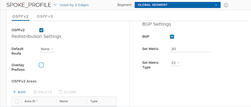
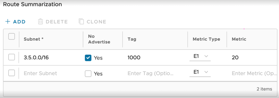
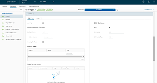
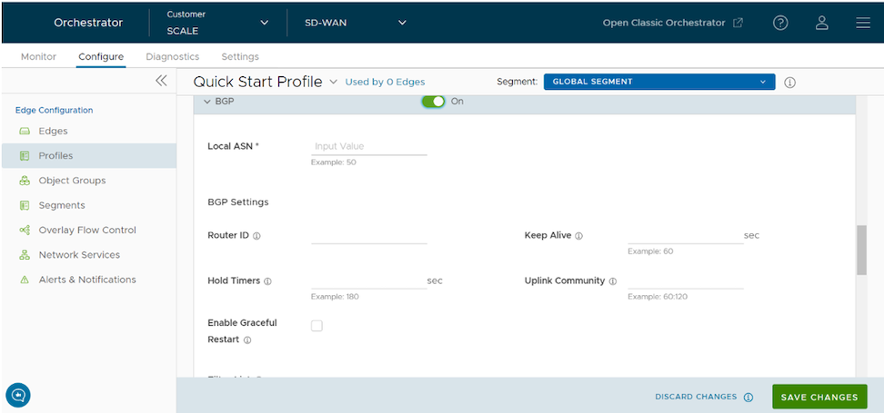

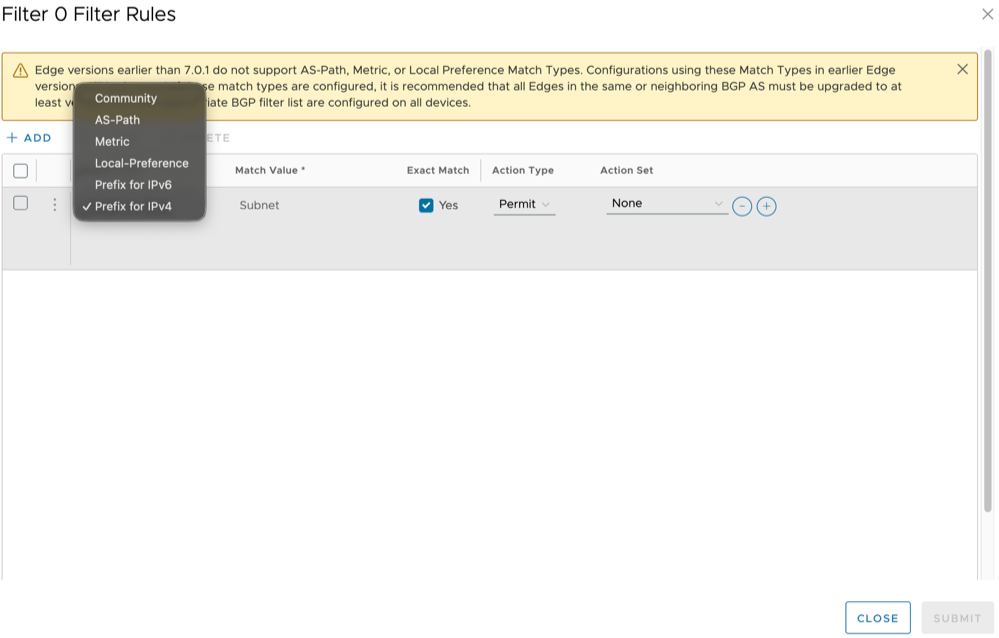
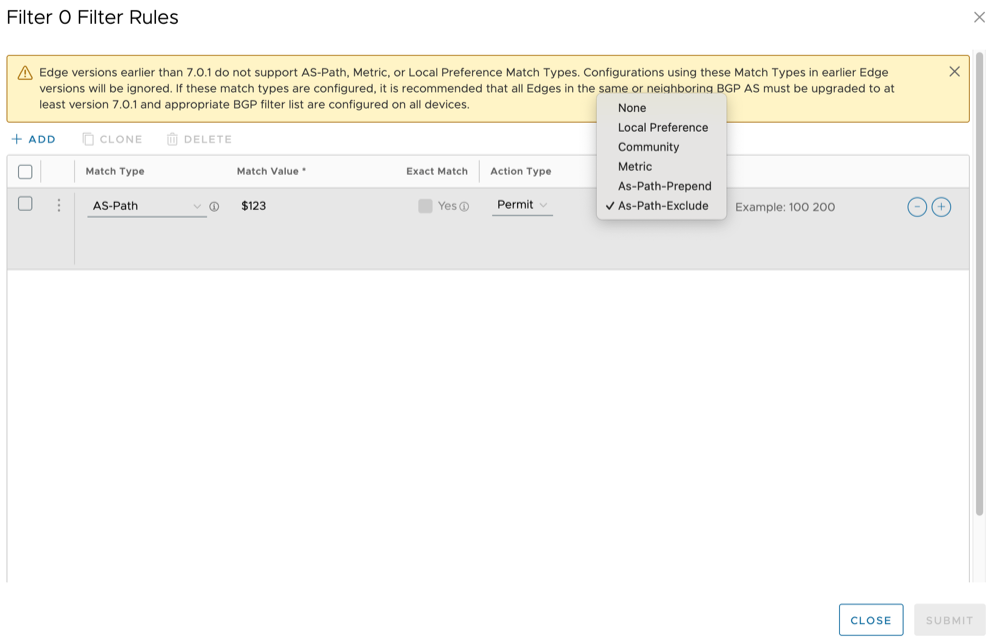
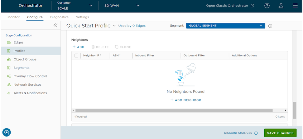
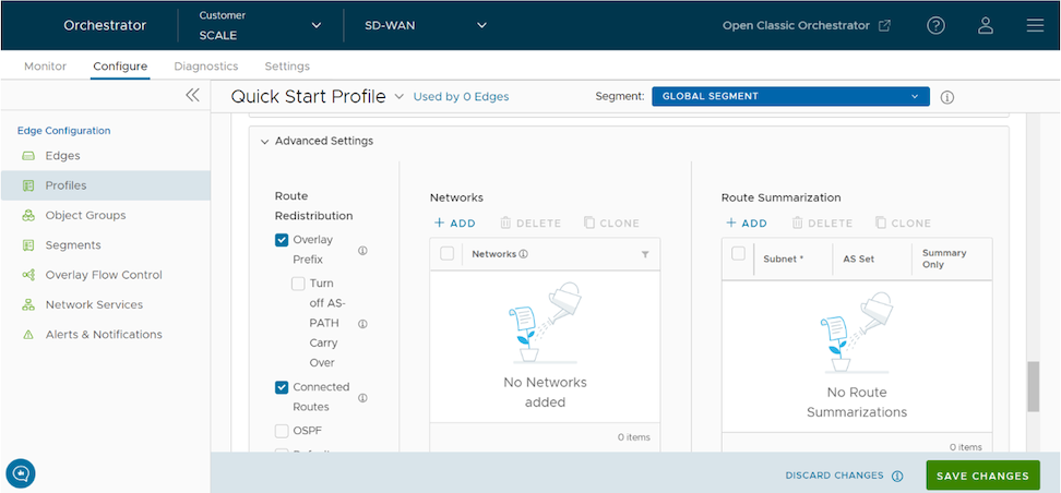
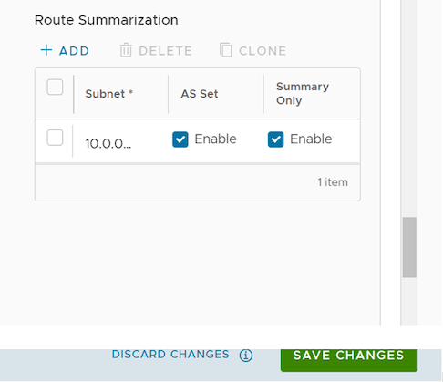
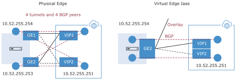
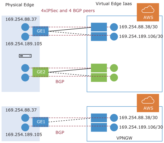
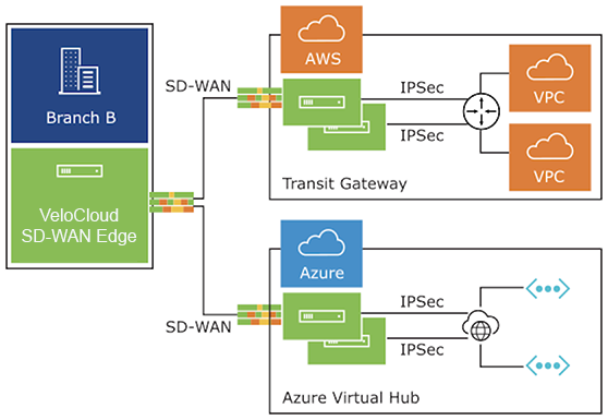
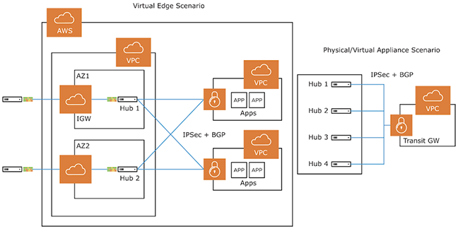
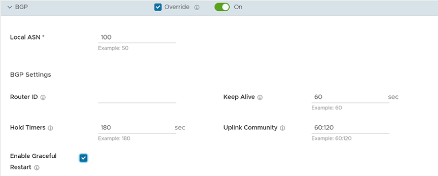
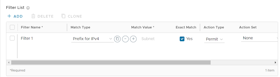
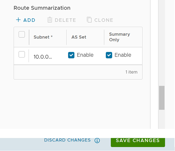
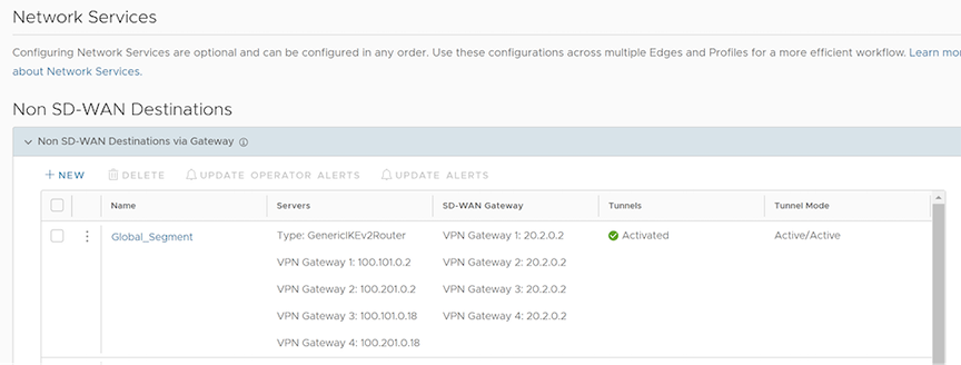

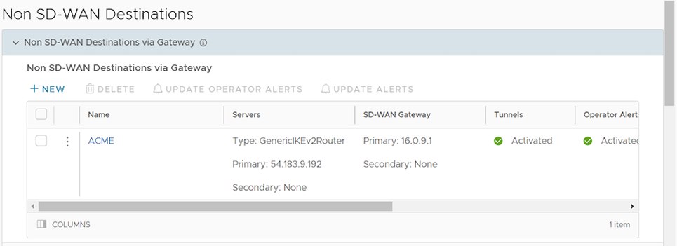
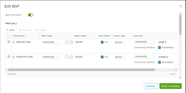
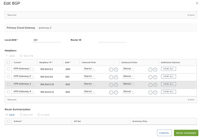 Note: The system assigns these BGP neighbors to their respective tunnels exclusively to establish neighborship and facilitate subsequent control exchanges. This configuration ensures that all such communication occurs solely over the designated tunnels.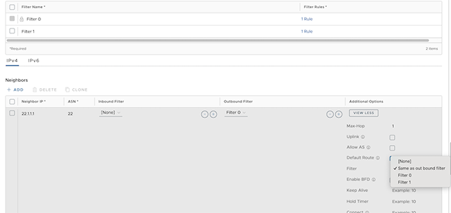
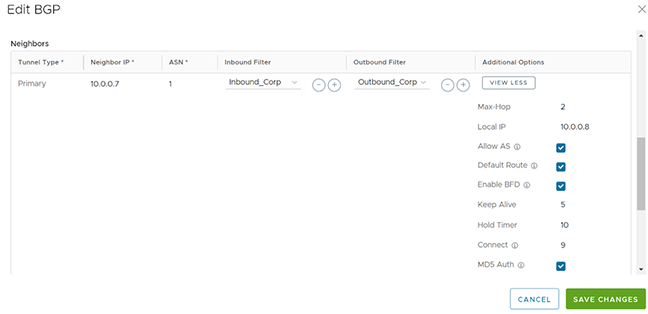 Note: In multi-hop BGP, the system might learn routes that require recursive lookups. These routes have a next-hop IP address that is not in a connected subnet and do not have a valid exit Interface. In this case, the routes must have the next-hop IP resolved using another route in the routing table that has an exit Interface. When there is traffic for a destination that needs these routes to be looked up, routes requiring recursive lookup will get resolved to a connected Next Hop IP address and Interface. Until the recursive resolution happens, the recursive routes point to an intermediate Interface. For additional information about Multi-hop BGP Routes, see the Remote Diagnostic Tests on Edges section in the VeloCloud SD-WAN Troubleshooting Guide.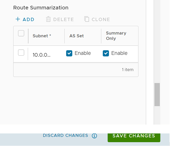
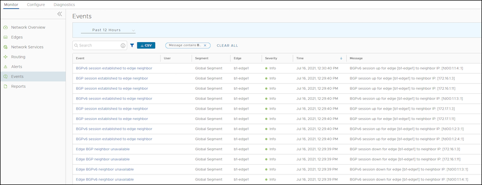
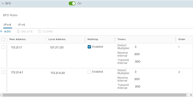
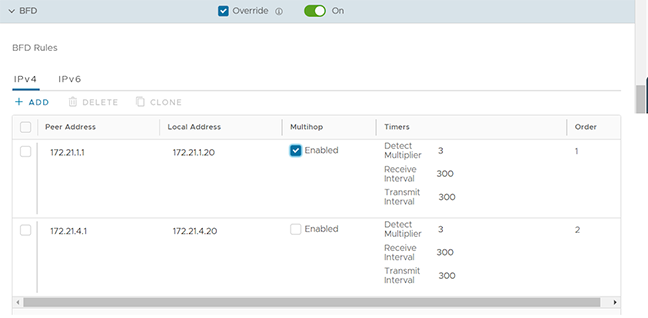
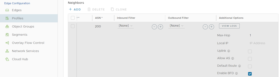 Note: BGP over Internet Protocol Security (IPsec) from the SD-WAN Edge does not support a single-hop BFD session.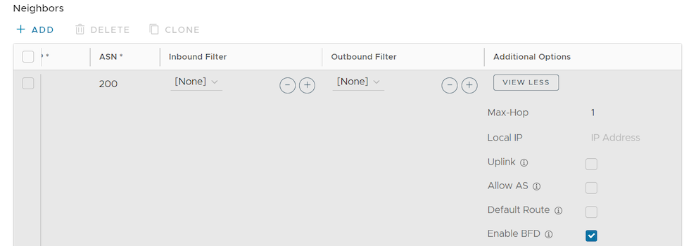
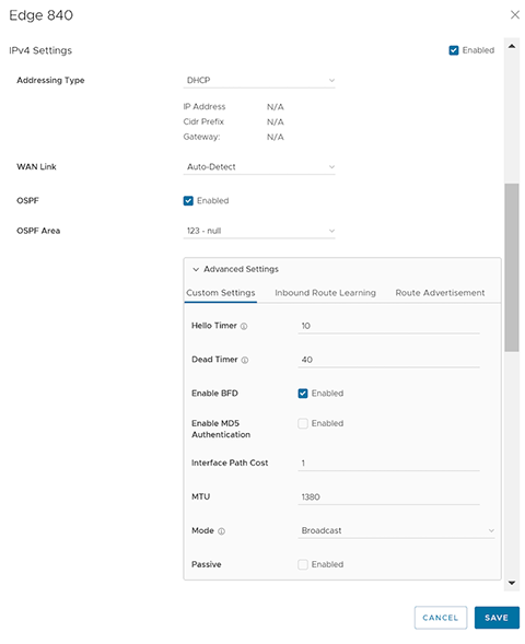
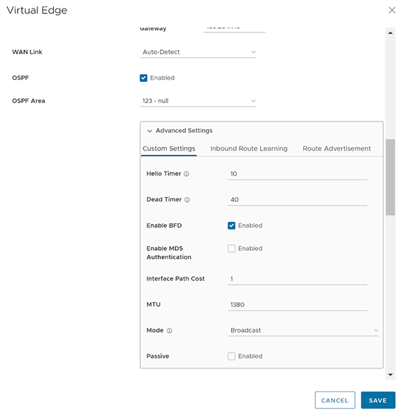
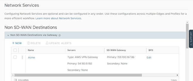
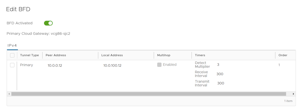
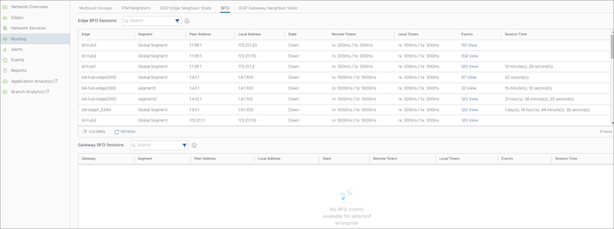 The BFD Sessions include the following details for Edges and Gateways: