Status Indicators
Front Indicators
Reviews the status and port indicators of the device.
Appliance Indicators
Describes the front panel LEDs for the Edge 4100 and Edge 5100 appliances.
On VeloCloud Edge 4100 appliance, the front panel LEDs are located on the far left side of the appliance front panel, just below the name panel (see image):
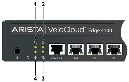
| 1 | ID/Locate LED (Blue) | 2 | SW Defined LED (Inactive) |
| 3 | Alert LED (Amber) | 4 | Power LED (Green) |
| LED Name | Color | Description | Software Controllable |
|---|---|---|---|
| Power button | Red |
Power button to power up or down Power On: LED on |
No |
| Power Off: LED Off | |||
| SW_Defined LED | Inactive | Inactive | |
| Alert LED | Amber | Behaviour linked with PEF, stays amber if there are any alert conditions detected by the sensors in the management controller (For example, PSU not working, high temperature, etc.) | Yes |
| ID or Locate LED | Blue | This is a blue LED that can be turned on and off via IPMI to quickly identifying the unit in a rack. | Yes |
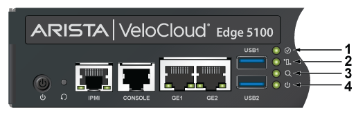
| 1 | SW Defined LED (Inactive) | 2 | Alert LED (Amber) |
| 3 | ID/Locate LED (Blue) | 4 | Power LED (Green) |
| LED Name | Color | Description | Software Controllable |
|---|---|---|---|
| Power button | Red |
Power button to power up or down Power On: LED on |
No |
| Power Off: LED Off | |||
| SW_Defined LED | Inactive | Inactive | |
| Alert LED | Amber | Behaviour linked with PEF, stays amber if there are any alert conditions detected by the sensors in the management controller (For example, PSU not working, high temperature, etc.) | Yes |
| ID or Locate LED | Blue | This is a blue LED that can be turned on and off via IPMI to quickly identifying the unit in a rack. | Yes |
Port Indicators
Port LEDs near their corresponding ports provide a link and operational status. The following figure displays the Port LED location on the Edge 4100 and Edge 5100 appliances.
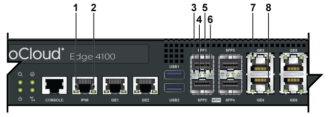
| 1 | IPMI Port LEDs | 2 | IPMI Port LEDs | 3 | SFP1 Port LEDs |
| 4 | SFP2 Port LEDs | 5 | SFP1 Port LEDs | 6 | SFP2 Port LEDs |
| 7 | GE3 Port LEDs | 8 | GE4 Port LEDs |
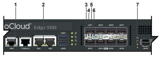
| 1 | IPMI Port LEDs | 2 | GE1 Port LEDs | 3 | SFP1 Port LEDs |
| 4 | SFP1 Port LEDs | 5 | SFP2 Port LEDs | 6 | SFP2 Port LEDs |
| 7 | SFP9 Port LEDs |
The following table provides status conditions corresponding to port LED states. Port LED behavior for GE and SFP+ ports is consistent.
| LED State | Status |
|---|---|
| Off | The port link is down. |
| Green | The port link is up. |
| Yellow | The port is software disabled. |
| Flashing Yellow | The port failed diagnostics. |
Rear Status Indicators
You can access the fan and power supply modules from the rear panel. Each fan and power supply module contains an LED that reports the module status. Fan Status LEDs are on the fan modules, as displayed in images below.
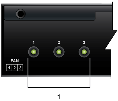
| 1 | Fan Status LEDs |
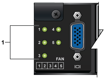
| 1 | Fan Status LEDs |
The AC Power Supply Status LEDs are on the power supply modules, as displayed in the Figure.
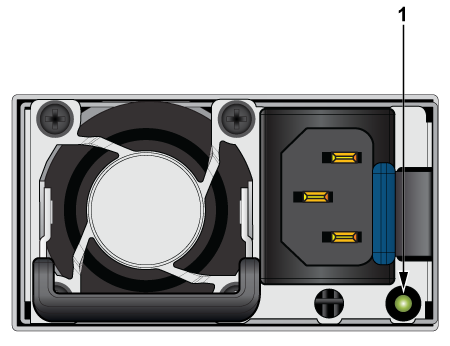
| 1 | AC Power Supply Status LEDs |
The table below provides conditions corresponding to the AC power supply status LED states and thefan status LED states.
| Numbering | LED Name | Color | Description | Software Controllable |
|---|---|---|---|---|
| 1 | PSU LED | Green | Normal, working condition | No |
| Amber | AC power cord unplugged or with waring or critical events | |||
| 1 | Fan LED | Green | Normal, working condition | No |
| Red | Fan failure |