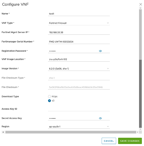
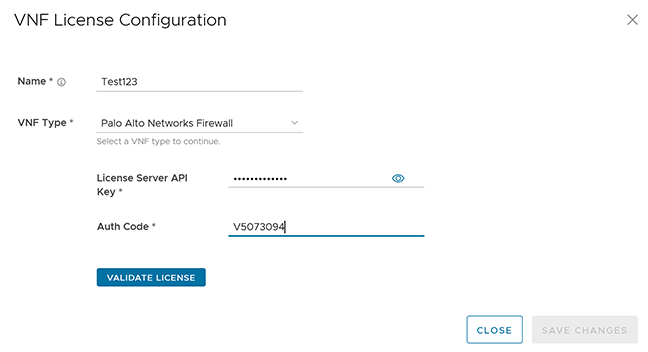
As an Enterprise user, Orchestrator allows users to configure a number of network services across multiple Edges and Profiles.
Note: If users login using a user ID with Customer Support privileges, users can only view the Orchestrator objects. Users cannot create new objects or configure/update existing ones.
To configure Network Services, select Configure > Network Services
Figure 1. Configure Network Services Homepage
Configure the following types of Network Services:
Note: Configuring Network Services is optional and can be configured in any order.
Configure a Non SD-WAN Destination
The Non SD-WAN Destination functionality consists of connecting a VeloCloud network to an external Network, such as Zscaler, Cloud Security Service, Azure, AWS, or Partner Data center, by creating a secure Internet Protocol Security (IPsec) tunnel between a VeloCloud entity and a VPN Gateway at the Network Provider. VeloCloud allows Enterprise users to define and configure a data center type using a Non SD-WAN Destination instance and establishing a secure tunnel directly to an External network in the following two ways:
Non SD-WAN Destinations via Gateway
Non SD-WAN Destinations via Edge
Non SD-WAN Destinations via Gateway - Allows an Gateway to establish an IPsec tunnel directly to a Non SD-WAN Destination. VeloCloud supports the following Non SD-WAN Destination configurations through Gateway:
AWS VPN Gateway
Check Point
Cisco ASA
Cisco ISR
Generic IKEv2 Router (Route Based VPN)
Microsoft Azure Virtual Hub
Palo Alto
SonicWALL
Zscaler
Generic IKEv1 Router (Route-based VPN)
Generic Firewall (Policy-based VPN)
VeloCloud supports both Generic Route-based and Policy-based Non SD-WAN Destination from Gateway.
Non SD-WAN Destinations via Edge - Allows an Edge to establish an IPsec tunnel directly to a Non SD-WAN Destination (AWS and Azure data center). VeloCloud supports the following Non SD-WAN Destination configurations through Edge:
Configure a Non SD-WAN Destination Network Service.
Associate a Non SD-WAN Destination Network Service to a Profile or Edge.
Configure Tunnel Parameters - WAN link selection and Per tunnel credentials.
Configure Business Policy.
VPN Workflow
An optional service that allows users to create VPN tunnel configurations to access one or more Non SD-WAN Destinations. VeloCloud provides the configuration required to create the tunnel(s) – including creating IKE IPsec configuration and generating a pre-shared key.
Overview
The following figure shows an overview of the VPN tunnels that can be created between VeloCloud and a Non SD-WAN Destination.
Figure 2. VPN Tunnels between VeloCloud and Non SD-WAN Destination
Note: The configuration requires a specified IP address for a Primary VPN Gateway at the Non SD-WAN Destination. The IP address forms a Primary VPN Tunnel between a Gateway and the Primary VPN Gateway.
Optionally, an IP address can be specified for a Secondary VPN Gateway to form a Secondary VPN Tunnel between a Gateway and the Secondary VPN Gateway. Using Advanced Settings, Redundant VPN Tunnels can be specified for any created VPN tunnels.
Important: Beginning with the 4.0 release, it is required that the AES-NI instruction set be supported by the CPU on all types of Virtual Machines.
Configure Non SD-WAN Destinations via Gateway
The VeloCloud solution enables Enterprise users to establish secure IPsec tunnels to Non SD-WAN Destinations (NSDs) through a Gateway. Using a geo-location service, the Orchestrator automatically selects the Gateway nearest to the NSD’s configured IP address.
Note: NSD configurations via a Gateway are defined exclusively at the Profile Level and cannot be overridden at the SD-WAN Edge level.
ECMP and Active-Active Mode
To maximize bandwidth utilization across ingress interfaces at Non SD-WAN sites, the VeloCloud SD-WAN Gateways support Active-Active mode. By establishing multiple IPsec tunnels simultaneously, the system can load-balance traffic flows, ensuring optimal distribution and redundancy.
Implementation Requirements
Implementing Active-Active mode with multiple IPsec tunnels requires the following configurations:
Tunnel Mode - Set the tunnels connecting to the NSD site to Active-Active.
Load Balancing - Selecting the preferred load balancing algorithm.
Routing - Configure BGP or Static site subnet routes to direct outbound traffic toward the NSD.
Use the following steps to configure a Non SD-WAN Destination through a Gateway:
In the SD-WAN service of the Enterprise portal, navigate to Configure > Network Services, and then under Non SD-WAN Destinations, expand Non SD-WAN Destinations via Gateway.
Figure 3. Configure Non SD-WAN Destinations
Select New or New NSD via Gateway option to create a new Non SD-WAN Destination. The New NSD via Gateway option displays only when no items exist in the table.
Figure 4. Configure Non SD-WAN Destinations via Gateway
Configure ECMP - Flow Load Based
Figure 5. Configure ECMP Load Sharing using Flow Load
Configure ECMP - Hash Load Based
Figure 6. Configure ECMP Load Sharing using Hash Load
Table 1. ECMP Load Sharing using Hash Load Option Descriptions
Option
Description
Name
Enter a name for the Non SD-WAN Destination in the text box.
Type
Select an IPsec tunnel type from the list of available options:
Note: Orchestrator does not support a Secondary VPN Gateway.
Tunnel Mode
Active/Hot-Standby mode supports to set up a maximum of 2 tunnel endpoints or Gateways. Active-Active mode supports a maximum of 4 tunnel endpoints or Gateways. All Active tunnels can send and receive traffic through ECMP. When users configure the Non SD-WAN Destination via Gateway type as Active/Hot-Standby and the peer end configured as Active/Active, then the Non SD-WAN Destination via Gateway accepts the traffic received over Hot-Standby tunnel.
ECMP
Load Sharing Method
Flow Load Based (Default) Flow load based algorithm maps the new flow to the path with least number of flows mapped among the available paths to the destination.
Hash Load Based algorithm takes input parameters from 5-tuple (SrcIP, DestIP, SrcPort, DestPort, Protocol). These inputs can be any or all or any subset of this tuple based on user configuration. A flow maps to the path based on hash value with selected inputs.
VPN Gateways
VPN Gateway 1
Enter a valid IP address.
VPN Gateway 2
Enter a valid IP address. (Optional)
VPN Gateway 3
Enter a valid IP address. (Optional)
VPN Gateway 4
Enter a valid IP address. (Optional).
The Gateway functions as the tunnel initiator in tunnel negotiation and cannot be configured to serve as the tunnel responder during the negotiation process.
Select Create and redirect to an additional configuration options page based on the selected IPsec tunnel type. Select each of the links in the table for more information on these tunnel types.
Following are the various options available under the Non SD-WAN Destinations via Gateway section:
Table 2. Non SD-WAN Destinations via Gateway Option Descriptions
Option
Description
Delete
Select an item and delete it.
Operator Alerts
Select an item and set the Operator Alert to On or Off.
Update Alerts
Select an item and update the previously set Operator Alert.
Columns
Select the columns to display or hidden on the page.
Users can also access these options by selecting the vertical ellipsis next to the item name in the table.
The Edit option takes users to the additional configuration settings screen.
Select the information icon at the top of the table to view the Conceptual Destination Diagram, and then hover across the diagram for more details.
Flow Pinning Behavior Existing flows pin to the same path as long as the path/route is available. These flows are not affected during mode or algorithm change.
Associate the Non SD-WAN Destination to a Profile. For more information, see:
Configure a Non SD-WAN Destination of Type AWS VPN Gateway
This service allows users to create VPN tunnel configurations with access to one or more Non SD-WAN Destinations. VeloCloud provides the configuration required to create the tunnel(s) – including creating IKE IPsec configuration and generating a pre-shared key.
Overview
The following figure shows an overview of the VPN tunnels that can be created between VeloCloud and a Non SD-WAN Destination.
Figure 7. Example Topology
The configuration requires specifying an IP address for a Primary VPN Gateway at the Non SD-WAN Destination. The IP address forms a Primary VPN Tunnel between a Gateway and the Primary VPN Gateway.
Optionally, specify an IP address for a Secondary VPN Gateway to form a Secondary VPN Tunnel between a Gateway and the Secondary VPN Gateway. Specify any redundant VPN Tunnels for any created VPN tunnels.
Configure a Non SD-WAN Destination of type AWS VPN Gateway
After users create a Non SD-WAN Destination for a AWS VPN Gateway , Orchestrator redirects to an additional configuration options page:
Figure 8. Configure a AWS VPN Gateway NSD
Figure 9. ConfigureAdditional NSD Settings
Users can configure the following tunnel settings, and then select Save Changes.
Table 4. Non SD-WAN Destinations via Gateway Option Descriptions
Option
Description
Name
Edit the previously entered name for the Non SD-WAN Destination.
Type
Displays the type as AWS VPN Gateway. Users cannot edit this option.
Enable Tunnel(s)
Select the toggle button to initiate the tunnel(s) from the SD-WAN Gateway to the AWS VPN Gateway.
Tunnel Mode
Active/Hot-Standby mode supports to set up a maximum of 2 tunnel endpoints or Gateways.
Active/Active mode supports a maximum of 4 tunnel endpoints or Gateways. All Active tunnels can send and receive traffic through ECMP.
ECMP Load Sharing Method
Flow Load Based (Default) Flow Load-based algorithm maps the new flow to the path with least number of flows mapped among the available paths to the destination.
Hash Load Based algorithm takes input parameters from 5-tuple (SrcIP, DestIP, SrcPort, DestPort, Protocol). These inputs can be any or all or any subset of this tuple based on user configuration. The flow maps to the path based on hash value with selected inputs.
VPN Gateway 1
Enter a valid IP address.
VPN Gateway 2
Enter a valid IP address. (Optional).
VPN Gateway 3
Enter a valid IP address. (Optional).
VPN Gateway 4
Enter a valid IP address. (Optional)
Public IP
Displays the IP address of the Primary VPN Gateway.
PSK
The Pre-Shared Key (PSK) is the security key for authentication across the tunnel. The Orchestrator generates a PSK by default. If users want to use their own PSK or password, enter it in the text box.
Encryption
Select either AES-128 or AES-256 as the AES algorithm key size to encrypt data. The configuration as a default value of AES-128.
DH Group
Select the Diffie-Hellman (DH) Group algorithm from the menu to generate keying material. The DH Group sets the strength of the algorithm in bits. The supported DH Groups are 2, 5, and 14. The default value is 2.
PFS
Select the Perfect Forward Secrecy (PFS) level for additional security. The configuration supports PFS levels as deactivated, 2, and 5 with a default value of 2.
Authentication Algorithm
Select the authentication algorithm for the VPN header. Select one of the supported Secure Hash Algorithm (SHA) functions from the menu:
SHA1(Default)
SHA256
SHA384
SHA512
IKE SA Lifetime(min)
Time when Internet Key Exchange (IKE) rekeying initiates for SD-WAN Edges. The minimum IKE lifetime is 10 minutes and maximum is 1440 minutes with a default value of 1440 minutes.
IPsec SA Lifetime(min)
Time when Internet Security Protocol (IPsec) rekeying initiates for Edges. The minimum IPsec lifetime is 3 minutes and maximum is 480 minutes (default).
DPD Type
Use the Dead Peer Detection (DPD) method to detect if the Internet Key Exchange (IKE) peer is alive or dead. If the peer is detected as dead, the device deletes the IPsec and IKE Security Association. Select either Periodic or onDemand from the menu. The default value is onDemand.
DPD Timeout(sec)
Enter the DPD timeout value. The internal DPD timer adds the DPD timeout value. Wait for a response from the DPD message before considering the peer to be dead (Dead Peer Detection). Prior to the 5.1.0 release, the default value is 20 seconds. For the 5.1.0 release and later, see the following list for the default value.
Note: Prior to the 5.1.0 release, users can deactivate DPD by configuring the DPD timeout timer to 0 seconds. However, for the 5.1.0 release and later, users cannot deactivate DPD by configuring the DPD timeout timer to 0 seconds. The DPD timeout value in seconds is added to the default minimum value of 47.5 seconds.
Secondary VPN Gateway
Select Add, and then enter the IP address of the Secondary VPN Gateway. Select Save Changes. The Secondary VPN Gateway is immediately created for this site and provisions a VeloCloud VPN tunnel to this Gateway.
Redundant VeloCloud Cloud VPN
Select to add redundant tunnels for each VPN Gateway. Changes made to Encryption, DH Group, or PFS of Primary VPN Gateway also apply to the redundant VPN tunnels, if configured.
Local Auth Id
Local authentication ID defines the format and identification of the local gateway. From the menu, choose from the following types and enter a value:
FQDN- The Fully Qualified Domain Name or hostname. For example: arista.com
User FQDN- The User Fully Qualified Domain Name in the form of email address. For example: This email address is being protected from spambots. You need JavaScript enabled to view it.
IPv4- The IP address used to communicate with the local gateway.
IPv6- The IP address used to communicate with the local gateway.
If users do not specify a value, Default is used as the local authentication ID.
Sample IKE / IPsec
Select to view the information needed to configure the Non SD-WAN Destination Gateway. The Gateway administrator should use this information to configure the Gateway VPN tunnel(s).
Location
Select Edit to set the location for the configured Non SD-WAN Destination. The latitude and longitude details are used to determine the best Edge or Gateway to connect to in the network.
Site Subnets
Activate or deactivate the Site Subnets. Select Add to add subnets for the Non SD-WAN Destination. If users do not need subnets for the site, select the subnet and select Delete.
Note:
To support the data center type Non SD-WAN Destination, users must configure Non SD-WAN Destination local subnets into VeloCloud system.
If there no site subnets configured, deactivate Site Subnets to activate the tunnel.
Configure a Non SD-WAN Destination of Type Check Point
The Gateway connects to the Check Point CloudGuard service using IKEv1/IPsec. There are two steps to configure a Check Point:
Configuring the Check Point CloudGuard service.
Configuring the Non SD-WAN Destination of type Check Point.
Users must perform the first step on the Check Point Infinity Portal and the second step on the Orchestrator.
Users must have an active Check Point account and login credentials to access the Check Point Infinity Portal.
Configure a Non SD-WAN Destination of Type Check Point
After users create a Non SD-WAN Destination configuration of the type Check Point, the site redirects to an additional configuration options page:
Figure 10. Configure a Check Point NSD
Figure 11. Configure Additional NSD Settings
Figure 12. Configure the Primary VPN Gateway Information
Configure the following tunnel settings:
Table 5. Non SD-WAN Destinations via Gateway Option Descriptions
Option
Description
Name
Users can edit the previously entered name for the Non SD-WAN Destination.
Type
Displays the type as Check Point. Users cannot edit this option.
Enable Tunnel(s)
Initiate the tunnel(s) from the Gateway to the Check Point VPN Gateway.
ECMP Load Sharing Method
Flow Load Based (Default) - A flow load-based algorithm maps the new flow to the path with the fewest number of flows mapped among the available paths to the destination.
Hash Load Based - An algorithm that takes input parameters from a 5-tuple source such as SrcIP, DestIP, SrcPort, DestPort, or Protocol. These inputs can be any, all, or any subset of this tuple based on the user configuration. Flow maps to the path based on a hash value with selected inputs.
VPN Gateway 1
Enter a valid IP address.
VPN Gateway 2
Enter a valid IP address. (Optional)
VPN Gateway 3
Enter a valid IP address. (Optional)
VPN Gateway 4
Enter a valid IP address. (Optional)
Public IP
Displays the IP address of the Primary VPN Gateway.
PSK
The Pre-Shared Key (PSK) is the security key for authentication across the tunnel. The Orchestrator generates a PSK by default. If users want to use a specific PSK or password, enter it in the field.
Encryption
Select either AES-128 or AES-256 as the AES algorithm key size to encrypt data. The default value uses AES-128.
DH Group
Select the Diffie-Hellman (DH) Group algorithm to use for generating keying material. The DH Group sets the strength of the algorithm in bits. The supported DH Groups are 2, 5, and 14. The default value is 2.
PFS
Select the Perfect Forward Secrecy (PFS) level for additional security. The supported PFS levels are deactivated, 2, and 5. The default value is 2.
Redundant VeloCloud Cloud VPN
Select to add redundant tunnels for each VPN Gateway. Changes made to Encryption, DH Group, or PFS of Primary VPN Gateway also apply to the redundant VPN tunnels, if configured.
Secondary VPN Gateway
Select Add, and then enter the IP address of the Secondary VPN Gateway. Select Save Changes. Orchestrator immediately creates the Secondary VPN Gateway for this site and provisions a VeloCloud VPN tunnel to this Gateway.
Local Auth Id
The Local authentication ID defines the format and identification of the local gateway. From the menu, select from the following types and enter a value:
FQDN - The Fully Qualified Domain Name or hostname, for example, arista.com
User FQDN - The User Fully Qualified Domain Name in the form of email address. For example: This email address is being protected from spambots. You need JavaScript enabled to view it.
IPv4 - The IP address used to communicate with the local gateway.
IPv6 - The IP address used to communicate with the local gateway.
Note:
If users do not specify a value, Orchestrator uses Default as the local authentication ID.
Checkpoint Non SD-WAN Destination uses the default local authentication ID value as the Gateway Interface Public IP.
Sample IKE / IPsec
View the information needed to configure the Non SD-WAN Destination Gateway. The Gateway administrator should use this information to configure the Gateway VPN tunnel(s).
Location
Select Edit to set the location for the configured Non SD-WAN Destination. The latitude and longitude details determines the best Edge or Gateway to connect to in the network.
Site Subnets
Activate or deactivate the Site Subnets. Select Add to add subnets for the Non SD-WAN Destination. If users do not need subnets for the site, select the subnet and then select Delete.
Note: To support the data center type of Non SD-WAN Destination, besides the IPsec connection, users must configure Non SD-WAN Destination local subnets into the VeloCloud system.
Select Save Changes.
Configure a Non SD-WAN Destination of Type Cisco ASA
Follow the steps to configure a Non SD-WAN Destination of type Cisco ASA in the Orchestrator.
After users create a Non SD-WAN Destination configuration of the type Cisco ASA, Orchestrator redirects to an additional configuration options page:
Figure 13. Configure a Cisco ASA NSD
Figure 14. ConfigureAdditional NSD Settings
Secondary VPN Gateway is not supported for the Cisco ASA service type.
Users can configure the following tunnel settings:
Table 6. Non SD-WAN Destinations via Gateway Option Descriptions
Option
Description
Name
Users can edit the previously entered name for the Non SD-WAN Destination.
Type
Displays the type as Cisco ASA. Users cannot edit this option.
Enable Tunnel(s)
Select to initiate the tunnel(s) from the Gateway to the Cisco ASA VPN Gateway.
Tunnel Mode
Active/Hot-Standby - Supports setting up a maximum of 2 tunnel endpoints or Gateways.
Active/Active - Supports setting up a maximum of 4 tunnel endpoints or Gateways. All Active tunnels can send and receive traffic through ECMP.
VPN Gateway 1
Enter a valid IP address.
Public IP
Displays the IP address of the Primary VPN Gateway.
PSK
The Pre-Shared Key (PSK) consists of the security key for authentication across the tunnel. The Orchestrator generates a PSK by default. If users want to provide a specific PSK or password, enter it in the field.
Encryption
Select either AES-128 or AES-256 as the AES algorithm key size to encrypt data. The default value uses AES-128.
DH Group
Select the Diffie-Hellman (DH) Group algorithm used to generate keying material. The DH Group sets the strength of the algorithm in bits. The supported DH Groups are 2, 5, and 14. The default value is 2.
PFS
Select the Perfect Forward Secrecy (PFS) level for additional security. The supported PFS levels are deactivated, 2, and 5. The default value is 2.
Local Auth Id
The Local Auth ID defines the format and identification of the local gateway. From the menu, select from the following types and enter a value:
FQDN - The Fully Qualified Domain Name or hostname, for example, arista.com.
User FQDN - The User Fully Qualified Domain Name in the form of an email address, for example,This email address is being protected from spambots. You need JavaScript enabled to view it..
IPv4 - The IPv4 address used to communicate with the local gateway.
IPv6 - The IPv6 address used to communicate with the local gateway.
Note:
If users do not specify a value, Orchestrator uses the Default as the local authentication ID.
For Cisco ASA Non SD-WAN Destination, the default local authentication ID value uses the Local IP address of the Gateway.
Sample IKE / IPsec
Select to view the information needed to configure the Non SD-WAN Destination Gateway. The Gateway administrator should use this information to configure the Gateway VPN tunnel(s).
Location
Select Edit to set the location for the configured Non SD-WAN Destination. The latitude and longitude details determines the best Edge or Gateway to connect to in the network.
Site Subnets
Activate or deactivate the Site Subnets. Select Add to add subnets for the Non SD-WAN Destination. If users do not need subnets for the site, select the subnet and then select Delete.
Note: To support the Non SD-WAN Destination data center, besides the IPsec connection, users must configure Non SD-WAN Destination local subnets into the VeloCloud system.
Custom Site Subnets
Override the source subnets routed to this VPN device. Normally, the source subnets derive from the Edge LAN subnets routed to this device.
Select Save Changes.
Configure a Non SD-WAN Destination of the Type Cisco ISR
Follow the steps to configure a Non SD-WAN Destination of the type Cisco ISR in the Orchestrator.
After users create a Non SD-WAN Destination configuration of the type Cisco ISR, Orchestrator redirects users to an additional configuration options page:
Figure 15. Configure a Cisco ISR NSD
Figure 16. ConfigureAdditional NSD Settings
Configure the following tunnel settings:
Table 7. Non SD-WAN Destinations via Gateway Option Descriptions
Option
Description
Name
Edit the previously entered name for the Non SD-WAN Destination. (Optional)
Type
Displays the type as Cisco ISR. Users cannot edit this option.
Tunnel Mode
Active/Hot-Standby - Supports setting up a maximum of 2 tunnel endpoints or Gateways.
Active/Active - Supports setting up a maximum of 4 tunnel endpoints or Gateways. All Active tunnels can send and receive traffic through ECMP.
ECMP Load Sharing Method
Flow Load Based (Default)- A flow load-based algorithm that maps the new flow to the path with the fewest number of flows mapped among the available paths to the destination.
Hash Load Based - Uses input parameters from a 5-tuple, such as SrcIP, DestIP, SrcPort, DestPort, or Protocol. These inputs can be any or all or any subset of this tuple based on user configuration. The flow is maps to the path based on the hash value with the selected inputs.
VPN Gateway 1
Enter a valid IP address.
VPN Gateway 2
Enter a valid IP address. (Optional)
VPN Gateway 3
Enter a valid IP address. (Optional)
VPN Gateway 4
Enter a valid IP address. (Optional)
Public IP
Displays the Primary VPN Gateway IP address.
PSK
The Pre-Shared Key (PSK) consists of the security key for authentication across the tunnel. The Orchestrator generates a PSK by default. If users want to provide a specific PSK or password, enter it in the field.
Encryption
Select either AES-128 or AES-256 as the AES algorithm key size to encrypt data. The default value uses AES-128.
DH Group
Select the Diffie-Hellman (DH) Group algorithm to generate keying material. The DH Group sets the strength of the algorithm in bits. The supported DH Groups are 2, 5, and 14. The default value is 2.
PFS
Select the Perfect Forward Secrecy (PFS) level for additional security. The supported PFS levels are deactivated, 2, and 5. The default value is deactivated.
Redundant Cloud VPN
Select to add redundant tunnels for each VPN Gateway. Changes made to Encryption, DH Group, or PFS of Primary VPN Gateway also apply to the redundant VPN tunnels, if configured.
Secondary VPN Gateway
Select Add, and then enter the IP address of the Secondary VPN Gateway. Select Save Changes. The configuration immediately creates the Secondary VPN Gateway for this site and provisions a VeloCloud VPN tunnel to this Gateway.
Sample IKE / IPsec
View the information needed to configure the Non SD-WAN Destination Gateway. The Gateway administrator should use this information to configure the Gateway VPN tunnel(s).
Location
Select Edit to set the location for the configured Non SD-WAN Destination. The latitude and longitude details determine the best Edge or Gateway to connect to in the network.
Site Subnets
Activate or deactivate the Site Subnets. Select Add to add subnets for the Non SD-WAN Destination. If users do not need subnets for the site, select the subnet and select Delete.
Note: To support the data center type of Non SD-WAN Destination, besides the IPsec connection, users must configure Non SD-WAN Destination local subnets on the VeloCloud system.
Note: For Cisco ISR Non SD-WAN Destination, by default, the local authentication ID value uses the Gateway Interface Local IP.
Select Save Changes.
Configure a Non SD-WAN Destination of Type Generic IKEv2 Router (Route-Based VPN)
Perform the following steps to configure a Non SD-WAN Destination of type Generic IKEv2 Router (Route Based VPN) in the Orchestrator:
After users create a Non SD-WAN Destination configuration of the type Generic IKEv2 Router (Route Based VPN), users are redirected to an additional configuration options page:
Figure 17. Configure a Generic IKEv2 Router (Route-Based VPN) NSD
Figure 18. Configure Additional NSD Settings
Users can configure the following tunnel settings:
Table 8. Non SD-WAN Destinations via Gateway option Descriptions
Option
Description
Name
Users can edit the previously entered name for the Non SD-WAN Destination.
Type
Displays the type as Generic IKEv2 Router (Route Based VPN). Users cannot edit this option.
Enable Tunnel(s)
Select the toggle button to initiate the tunnel(s) from the SD-WAN Gateway to the Generic IKEv2 Router VPN Gateway.
Tunnel Mode
Active/Hot-Standby mode supports to set up a maximum of 2 tunnel endpoints or Gateways.
Active/Active mode supports to set up a maximum of 4 tunnel endpoints or Gateways. All Active tunnels can send and receive traffic through ECMP.
ECMP Load Sharing Method
Flow Load Based (Default) Flow load based algorithm maps the new flow to the path with least number of flows mapped among the available paths to the destination.
Hash Load Based algorithm takes input parameters from 5-tuple (SrcIP, DestIP, SrcPort, DestPort, Protocol). These inputs can be any or all or any subset of this tuple based on user configuration. Flow is mapped to the path based on hash value with selected inputs.
VPN Gateway 1
Enter a valid IP address.
VPN Gateway 2
Enter a valid IP address. This field is optional.
VPN Gateway 3
Enter a valid IP address. This field is optional.
VPN Gateway 4
Enter a valid IP address. This field is optional.
Public IP
Displays the IP address of the Primary VPN Gateway.
PSK
The Pre-Shared Key (PSK) is the security key for authentication across the tunnel. The Orchestrator generates a PSK by default. If users want to use their own PSK or password, enter it in the text box.
Encryption
Select either AES-128 or AES-256 as the AES algorithm key size to encrypt data. The default value is AES-128.
DH Group
Select the Diffie-Hellman (DH) Group algorithm from the drop-down menu. This is used for generating keying material. The DH Group sets the strength of the algorithm in bits. The supported DH Groups are 2, 5, and 14. The default value is 2.
PFS
Select the Perfect Forward Secrecy (PFS) level for additional security. The supported PFS levels are deactivated, 2, and 5. The default value is 2.
Authentication Algorithm
Select the authentication algorithm for the VPN header. Select one of the supported Secure Hash Algorithm (SHA) functions from the drop-down menu:
SHA1
SHA256
SHA384
SHA512
The default value is SHA 1.
IKE SA Lifetime(min)
Time when Internet Key Exchange (IKE) rekeying is initiated for SD-WAN Edges. The minimum IKE lifetime is 10 minutes and maximum is 1440 minutes. The default value is 1440 minutes.
IPsec SA Lifetime(min)
Time when Internet Security Protocol (IPsec) rekeying is initiated for Edges. The minimum IPsec lifetime is 3 minutes and maximum is 480 minutes. The default value is 480 minutes.
DPD Type
The Dead Peer Detection (DPD) method is used to detect if the Internet Key Exchange (IKE) peer is alive or dead. If the peer is detected as dead, the device deletes the IPsec and IKE Security Association. Select either Periodic or on Demand from the drop-down menu. The default value is on Demand.
DPD Timeout(sec)
Enter the DPD timeout value. The DPD timeout value will be added to the internal DPD timer, as described below. Wait for a response from the DPD message before considering the peer to be dead (Dead Peer Detection). Prior to the 5.1.0 release, the default value is 20 seconds. For the 5.1.0 release and later, see the list below for the default value.
Note: Prior to the 5.1.0 release, users can deactivate DPD by configuring the DPD timeout timer to 0 seconds. However, for the 5.1.0 release and later, users cannot deactivate DPD by configuring the DPD timeout timer to 0 seconds. The DPD timeout value in seconds is added onto the default minimum value of 47.5 seconds.
Redundant Cloud VPN
Select the check box to add redundant tunnels for each VPN Gateway. Changes made to Encryption, DH Group, or PFS of Primary VPN Gateway also apply to the redundant VPN tunnels, if configured.
Secondary VPN Gateway
Select the Add button, and then enter the IP address of the Secondary VPN Gateway. Select Save Changes. The Secondary VPN Gateway is immediately created for this site and provisions a VPN tunnel to this Gateway.
Local Auth Id
Local authentication ID defines the format and identification of the local gateway. From the drop-down menu, choose from the following types and enter a value:
FQDN- The Fully Qualified Domain Name or hostname. For example: arista.com
User FQDN- The User Fully Qualified Domain Name in the form of email address. For example: This email address is being protected from spambots. You need JavaScript enabled to view it.
IPv4- The IP address used to communicate with the local gateway.
IPv6- The IP address used to communicate with the local gateway.
Note:
If users do not specify a value, Default is used as the local authentication ID.
The default local authentication ID value is the Gateway Interface Public IP.
Sample IKE / IPsec
Select to view the information needed to configure the Non SD-WAN Destination Gateway. The Gateway administrator should use this information to configure the Gateway VPN tunnel(s).
Location
Select Edit to set the location for the configured Non SD-WAN Destination. The latitude and longitude details are used to determine the best Edge or Gateway to connect to in the network.
Site Subnets
Use the toggle button to activate or deactivate the Site Subnets. Select Add to add subnets for the Non SD-WAN Destination. If users do not need subnets for the site, select the subnet and select Delete.
Note:
To support the data center type of Non SD-WAN Destination, besides the IPsec connection, users must configure Non SD-WAN Destination local subnets into the Arista system.
If there are no site subnets configured, deactivate Site Subnets to activate the tunnel.
Note: When AWS initiates the rekey tunnel with a VeloCloud Gateway (in Non SD-WAN Destinations), a failure can occur and the tunnel may not be established, which can cause traffic interruption. In this case, adhere to the following:
IPsec SA Lifetime (min) timer configurations for the Gateway must be less than 60 minutes (recommended value = 50 minutes), to match the AWS default IPsec configuration.
DH Group and PFS values must be matched.
Select Save Changes.
Configure a Non SD-WAN Destination of Type Microsoft Azure Virtual Hub
Follow the steps to configure a Non SD-WAN Destination of the type Microsoft Azure Virtual Hub in the Orchestrator.
In the SD-WAN service of the Enterprise portal, go to Configure > Network Services, and then under Non SD-WAN Destinations, expand Non SD-WAN Destinations via Gateway.
Select New, enter the Name, and select the Type of the Non SD-WAN Destination. After the user enters the Type as Microsoft Azure Virtual Hub, the Virtual Hub Configuration section displays:
Figure 19. Configure a Microsoft Azure Virtual Hub NSD
Users can configure the following settings:
Table 9. Non SD-WAN Destinations via Gateway Option Descriptions
Option
Description
Name
Edit the previously entered name for the Non SD-WAN Destination. (Optional)
Type
Displays the type as Microsoft Azure Virtual Hub. Users cannot edit this option.
Tunnel Mode
Active/Hot-Standby - Supports setting up a maximum of 2 tunnel endpoints or Gateways.
Active/Active - Supports setting up a maximum of 4 tunnel endpoints or Gateways. All Active tunnels can send and receive traffic through ECMP.
ECMP Load Sharing Method
Flow Load Based (Default) - A flow load-based algorithm maps the new flow to the path with the fewest number of flows mapped among the available paths to the destination.
Hash Load Based - Uses input parameters from a 5-tuple such as SrcIP, DestIP, SrcPort, DestPort, or Protocol. These inputs can be any or all or any subset of this tuple based on user configuration. The flow maps to the path based on hash value with selected inputs.
Subscription
Select a subscription from the menu.
Virtual WAN
The application obtains all of the available Virtual WANs dynamically from Azure. Select a virtual WAN from the menu.
Resource Group
The application auto-populates the resource group with the selected Virtual WAN.
Virtual Hub
Select a virtual Hub from the menu.
Azure Region
The application auto-populates the Azure region corresponding to the selected Virtual Hub.
Enable Tunnel(s)
Select Enable Tunnel(s) to allow VPN Gateways to initiate VPN connections to the target Virtual Hub as soon as the site successfully provisions.
VeloCloud VPN Gateways initiate the IKE negotiation only when at least one profile has a Non SD-WAN Destination configured.
For Microsoft Azure Non SD-WAN Destination, the configuration uses the default local authentication ID value as the Gateway Interface Public IP.
Select Create. Orchestrator automatically initiates deployment, provisions Azure VPN Sites, and downloads the VPN Site Configuration for the newly configured sites. It stores the configuration in the Orchestrator’s Non SD-WAN Destination configuration database.
Figure 20. New Non SD-WAN Destination via Gateway
Once the Azure VPN sites provision at the Orchestrator side, users can view the VPN sites (Primary and Redundant) in the Azure portal by navigating to Virtual WAN Virtual WAN architecture VPN sites.
Associate the Microsoft Azure Non SD-WAN Destination to a Profile to establish a tunnel between a branch and Azure Virtual Hub. For additional information, see Associate a Microsoft Azure with an SD-WAN Profile.
Users must add SD-WAN routes into Azure network manually. For additional information, see Edit a VPN Site.
After associating a Profile to the Microsoft Azure Non SD-WAN Destination, users can return to the Non SD-WAN Destinations via Gateway section by navigating to Configure > Network Services and then configure the BGP settings for the Non SD-WAN Destination. Scroll to the name of the Non SD-WAN Destination, and then select the Edit link in the BGP column. For additional information, see Configure BGP Over IPsec from Gateways.
In the Non SD-WAN Destinations via Gateway section, select the Edit link in the BFD column for a Non SD-WAN Destination, to configure the BFD settings. For additional information, see Configure BFD for Gateways.
Configure a Non SD-WAN Destination of Type Palo Alto
Follow the steps to configure a Non SD-WAN Destination of the type Palo Alto in the Orchestrator.
After users have created a Non SD-WAN Destination configuration of the type Palo Alto, users are redirected to an additional configuration options page:
Figure 21. Configure a Palo Alto NSD
Figure 22. Configure Additional NSD Settings - Example 1
Figure 23. Configure Additional NSD Settings - Example 2
Figure 24. Configure Additional NSD Settings - Example 3
Configure the following tunnel settings:
Table 10. Non SD-WAN Destinations via Gateway Option Descriptions
Option
Description
Name
Users can edit the previously entered name for the Non SD-WAN Destination.
Type
Displays the type as Palo Alto. Users cannot edit this option.
Enable Tunnel(s)
Select to initiate the tunnel(s) from the SD-WAN Gateway to the Palo Alto VPN Gateway.
Tunnel Mode
Active/Hot-Standby mode supports to set up a maximum of 2 tunnel endpoints or Gateways.
Active/Active mode supports to set up a maximum of 4 tunnel endpoints or Gateways. All Active tunnels can send and receive traffic through ECMP.
ECMP Load Sharing Method
Flow Load Based (Default) A flow load based algorithm maps the new flow to the path with the fewest number of flows mapped among the available paths to the destination.
Hash Load Based - Uses input parameters from a 5-tuple such as SrcIP, DestIP, SrcPort, DestPort, or Protocol. These inputs can be any, all, or any subset of this tuple based on user configuration. The flow maps to the path based on hash value with selected inputs.
VPN Gateway 1
Enter a valid IP address.
VPN Gateway 2
Enter a valid IP address. (Optional)
VPN Gateway 3
Enter a valid IP address. (Optional)
VPN Gateway 4
Enter a valid IP address. (Optional)
Primary VPN Gateway
Public IP
Displays the IP address of the Primary VPN Gateway.
PSK
The Pre-Shared Key (PSK) provides the security key for authentication across the tunnel. The Orchestrator generates a PSK by default. If users want to use a specific PSK or password, enter it into the field.
Encryption
Select either AES-128 or AES-256 as the AES algorithm key size to encrypt data. The default value is AES-128.
DH Group
Select the Diffie-Hellman (DH) Group algorithm used for generating keying material. The DH Group sets the strength of the algorithm in bits. The supported DH Groups are 2, 5, and 14. The default value is 2. It is recommended to use DH Group 14. The Non SD-WAN Destination via Gateway of type Palo Alto does not support any value higher than 14.
PFS
Select the Perfect Forward Secrecy (PFS) level for additional security. The supported PFS levels are deactivated, 2, and 5. The default value is 5.
Redundant VeloCloud Cloud VPN
Select to add redundant tunnels for each VPN Gateway. Changes made to Encryption, DH Group, or PFS of Primary VPN Gateway also apply to the redundant VPN tunnels, if configured.
Secondary VPN Gateway
Select Add, and then enter the IP address of the Secondary VPN Gateway. Select Save Changes. Orchestrator immediately creates the Secondary VPN Gateway for this site and provisions a VeloCloud VPN tunnel to this Gateway.
Sample IKE / IPsec
Select to view the information needed to configure the Non SD-WAN Destination Gateway. The Gateway administrator should use this information to configure the Gateway VPN tunnel(s).
Location
Select Edit to set the location for the configured Non SD-WAN Destination. The latitude and longitude details determine the best Edge or Gateway to connect to in the network.
Site Subnets
Activate or deactivate the SiteSubnets. Select Add to add subnets for the Non SD-WAN Destination. If users do not need subnets for the site, select the subnet and select Delete.
To support the Non SD-WAN Destination type of data center, besides the IPsec connection, users must configure Non SD-WAN Destination local subnets into the VeloCloud system.
If no site subnets configured, deactivate Site Subnets to activate the tunnel.
For Palo Alto Non SD-WAN Destination, the default local authentication ID value uses the Gateway Interface Public IP.
The Palo Alto Non SD-WAN Destination template uses the below parameters:
IKE Version - IKEv1
Phase 1 Lifetime - 86400 seconds
Phase 2 Lifetime - 28800 seconds
Select Save Changes.
Configure a Non SD-WAN Destination of Type SonicWall
Perform the following steps to configure a Non SD-WAN Destination of type SonicWALL in the Orchestrator.
After users have created a Non SD-WAN Destination configuration of the type SonicWALL, users are redirected to an additional configuration options page:
Figure 25. Configure a SonicWall NSD
Figure 26. Configure General Settings - Example 1
Figure 27. Configure General Settings - Example 2
Figure 28. Configure General Settings - Example 3
Configure the following tunnel settings:
Table 11. Non SD-WAN Destinations via Gateway Option Descriptions
Option
Description
Name
Edit the previously entered name for the Non SD-WAN Destination. (Optional)
Type
Displays the type as SonicWALL. Users cannot edit this option.
Enable Tunnel(s)
Select to initiate the tunnel(s) from the SD-WAN Gateway to the SonicWALL VPN Gateway.
Tunnel Mode
Active/Hot-Standby mode supports setting up a maximum of two tunnel endpoints or Gateways.
Active/Active mode supports setting up a maximum of four tunnel endpoints or Gateways. All Active tunnels can send and receive traffic through ECMP.
ECMP Load Sharing Method
Flow Load Based (Default) - The flow load-based algorithm maps the new flow to the path with the fewest number of flows mapped among the available paths to the destination.
Hash Load Based - Uses input parameters from a 5-tuple such as SrcIP, DestIP, SrcPort, DestPort, or Protocol. These inputs can be any or all or any subset of this tuple based on user configuration. The flow maps to the path based on the hash value of the selected inputs.
VPN Gateway 1
Enter a valid IP address.
VPN Gateway 2
Enter a valid IP address. (Optional)
VPN Gateway 3
Enter a valid IP address. (Optional)
VPN Gateway 4
Enter a valid IP address. (Optional)
Public IP
Displays the IP address of the Primary VPN Gateway.
PSK
The Pre-Shared Key (PSK) provides the security key for authentication across the tunnel. Orchestrator generates a PSK by default. If users want to use a specific PSK or password, enter it in the field.
Encryption
Select either AES-128 or AES-256 as the AES algorithm key size to encrypt data. The default value is AES-128.
DH Group
Select the Diffie-Hellman (DH) Group algorithm used for generating keying material. The DH Group sets the strength of the algorithm in bits. The supported DH Groups are 2, 5, and 14. The default value is 2.
PFS
Select the Perfect Forward Secrecy (PFS) level for additional security. The supported PFS levels are deactivated, 2, and 5. The default value is 2.
Redundant Cloud VPN
Select to add redundant tunnels for each VPN Gateway. Changes made to Encryption, DH Group, or PFS of Primary VPN Gateway also apply to the redundant VPN tunnels, if configured.
Secondary VPN Gateway
Select Add, and then enter the IP address of the Secondary VPN Gateway. Select Save Changes. Orchestrator immediately creates the Secondary VPN Gateway for this site and provisions a VeloCloud VPN tunnel to this Gateway.
Sample IKE / IPsec
Select to view the information needed to configure the Non SD-WAN Destination Gateway. The Gateway administrator should use this information to configure the Gateway VPN tunnel(s).
Location
Select Edit to set the location for the configured Non SD-WAN Destination. The latitude and longitude details determine the best Edge or Gateway to connect to in the network.
Site Subnets
Activate or deactivate the Site Subnets. Select Add to add subnets for the Non SD-WAN Destination. If users do not need subnets for the site, select the subnet and select Delete.
To support the Non SD-WAN Destination data center type, besides the IPsec connection, users must configure Non SD-WAN Destination local subnets into the VeloCloud system.
If users have not configured site subnets, deactivate Site Subnets to activate the tunnel.
For a SonicWALL Non SD-WAN Destination, the default local authentication ID value uses the Gateway Interface Public IP.
Select Save Changes.
Zscaler and VeloCloud SD-WAN Integration
Enterprises leverage a secure local Internet breakout by utilizing VeloCloud SD-WAN integrated with Zscaler. Using VeloCloud SD-WAN, the network administrator can decide what traffic should be forwarded to Zscaler, using IPsec tunnels (with NULL encryption).
Prerequisites
The prerequisites to provision a new service with Zscaler and VeloCloud SD-WAN consist of the following:
Zscaler Internet Access (ZIA)
A working instance of ZIA (any cloud)
Administrator login credentials
VeloCloud Orchestrator
Enterprise account access to VeloCloud Orchestrator
Administrator login credentials
One or more VeloCloud Edge appliances with an Online status in VeloCloud Orchestrator
Zscaler Gateway Selection and Routing Behavior
The VeloCloud Orchestrator configuration process for building tunnels to Zscaler does not require the manual selection of specific VeloCloud Gateways. Using a geo-IP lookup process, Orchestrator dynamically chooses VeloCloud Gateways based on proximity to the provided Zscaler IP endpoint. Operator and Partner Administrators with sufficient permissions can manually override the default Orchestrator Gateway selections. The recommended best practice is to accept the Gateways as chosen by the system. After the Zscaler configuration completes on the Orchestrator and the tunnels up and active, Operator and Partner Administrators with sufficient permissions can verify the chosen Gateways . To verify the selected Gateways, log into the Orchestrator and go to Operator > Gateways. Select on a specific Gateway and look for Secure VPN Gateway. The Secure VPN Gateway displays the name of the Zscaler setup as set during the configuration process. The primary Gateway has the Zscaler Name, and the redundant Gateway displays Zscaler_Name[redundant].
Figure 29. Identify the Secure VPN Gateway
To set the Zscaler tunnel to a specific Gateway, users must first locate the Gateway with the tunnel by following the process. From there select Secure VPN Gateway and move or assign the tunnel to a different Gateway.
Locate current tunnel location.
Figure 30. Locate the Current Tunnel Location
Select a Gateway.
Figure 32. Assign Secure VPN Gateway for Zscaler
Assigning or moving a tunnel to a different Gateway affects the service. The existing tunnel connection terminates and establishes a new tunnel from the newly assigned Gateway. During the VeloCloud Edge configuration or activation process, the configuration assigns each Edge a pair of cloud Gateways or a set of Partner Gateways. If the Gateways used by the Edge are not the same Gateways which contain the Zscaler tunnels, the Edge automatically builds VCMP tunnels to the Gateways that connect to Zscaler. In addition to the Gateways selected during the activation process, and ensures the Edge has a path to reach Zscaler.
Zscaler Setup Examples
Example 1: Primary Zscaler tunnel to 1.1.1.1 with NO Redundant VeloCloud Cloud VPN Selected.
Figure 33. Primary Zscaler Tunnel
Figure 34. Example Topology
In this example, Orchestrator created only one Zscaler VPN tunnel, and did not select the Redundant VeloCloud Cloud VPN. A single Gateway, the Primary Gateway in this case, selected based on the proximity to the remote VPN Gateway as determined using Geo-IP lookup, creates an IPsec tunnel to the Zscaler VPN endpoint. Dependent on Business Policy configuration, traffic flows from the Edge to the Primary Gateway, and then on to Zscaler. Even though the Edge always has VCMP tunnels to at least two Gateways, the design has no redundancy. Since the Redundant VeloCloud Cloud VPN is not selected, there is not a backup Gateway tunnel to Zscaler. If either Zscaler or the primary Gateway fails or if the IPsec tunnel between the two goes down for any reason traffic to Zscaler drops.
Example 2: Primary Zscaler tunnel to 1.1.1.1 with Redundant VeloCloud Cloud VPN Selected.
Figure 35. Primary Zscaler Tunnel with Redundant VeloCloud Cloud VPN
Figure 36. Single Zscaler VPN Tunnel
In this example, Orchestrator created only one Zscaler VPN tunnel created, and Redundant VeloCloud Cloud VPN selected. Two Gateways selected based on the proximity to the remote VPN Gateway, as determined using the Geo-IP lookup feature,closest to the Zscaler location builds IPsec tunnels to Zscaler. Both of these tunnels remain active, however all traffic to Zscaler traverses through the Primary Gateway. If the Primary Gateway fails, traffic then shifts to the Secondary Gateway. Since only a single Zscaler endpoint is defined and traffic stops, traffic to Zscaler drops.
Example 3: Primary Zscaler tunnel to 1.1.1.1, Secondary Zscaler tunnel to 2.2.2.2 with NO Redundant VeloCloud Cloud VPN Selected
Figure 37. Primary and Secondary Zscaler Tunnels
Figure 38. Example Topology
In this example, Orchestrator configured redundant IPsec tunnels to Zscaler by adding a secondary Zscaler IP address, and Redundant VeloCloud Cloud VPN not selected. A single Gateway selected based on the proximity to the remote VPN Gateway, as determined using theGeo-IP lookup feature,creates an IPsec tunnel to both Zscaler VPN endpoints. Both of these tunnels remain active, but by the configuration settings, the Gateway recognizes which IPsec tunnel to Zscaler has the primary path and sends traffic through that tunnel. Zscaler does not mark primary or backup IPsec tunnels. Zscaler simply returns traffic through the Gateway that originated the request. If the primary Zscaler location goes down, traffic from the Gateway shifts to the secondary Zscaler IPsec tunnel. Since Redundant VeloCloud Cloud VPN was not selected, there are no redundant Gateway connections to Zscaler. If the Gateway fails, then traffic to Zscaler drops.
Example 4: Primary Zscaler tunnel to 1.1.1.1, Secondary Zscaler tunnel to 2.2.2.2 with Redundant VeloCloud VPN Selected.
Figure 39. Primary and Secondary Zscaler Tunnel with Redundant VeloCloud VPN
Figure 40. Example Topology
In this example, Orchestrator configured redundant IPsec tunnels to Zscaler by adding a secondary Zscaler IP address and Redundant VeloCloud Cloud VPN selected. Two Gateways selected based on the proximity to the remote VPN Gateway, as determined using the Geo-IP lookup feature, creates IPsec tunnels to both Zscaler VPN endpoints. All of these tunnels remain active, but by the configuration settings, the Gateways recognize which of the two has the primary Gateway and which has the secondary. The Gateways also understand which of the IPsec tunnels to Zscaler has the primary path and which has the secondary path. Zscaler does not mark primary or backup IPsec tunnels. Zscaler simply returns traffic through the Gateway that originated the request. Ifthe primary Zscaler location goes down, traffic from the primary Gateway shifts to the secondary Zscaler IPsec tunnel. Since the configuration has Redundant VeloCloud Cloud VPN selected, if the primary Gateway fails, traffic shifts to the secondary Gateway. The secondary Gateway utilizes the primary IPsec tunnel provided with the available path. If not, it uses the secondary IPsec tunnel to reach Zscaler.
Layer 7 Health Checks
When users establish an IPsec/GRE tunnel to a Zscaler data center for Zscaler Internet Access (ZIA), Orchestrator creates a tunnel between the Edge or the Gateway to a virtual IP (VIP) on a Zscaler load balancer for ZIA. When the end user traffic from the branch reaches the load balancer, the load balancer distributes traffic to ZIA Public Service Edges. Dead Peer Detection (DPD) and GRE keepalive can only detect the availability of the public VIP on the load balancer since it has the tunnel destination. The public VIP has a highly available endpoint and does not reflect the availability of a given ZIA Public Service Edge. Layer 7 health checking allows users to monitor the performance and availability of ZIA Edges based on HTTP probes and allows users to failover to an alternate tunnel based on the results. The Edge or Gateway sends probe requests periodically to the HTTP probe URL, in the following format, if the probe activates.
http://gateway.<zscaler_cloud>.net/vpntest
The probe URL can be configured on the Orchestrator, but users cannot edit the probe interval and number of retries. If the probe fails consecutively for the number of defined retries, the tunnel becomes down, and the traffic fails over to the secondary tunnel if defined. The probe failure could be due to the HTTPS response, 200 OK, not received, or the latency becomes greater than the defined threshold. If the conditional backhaul has a configured Edge, probe failures to both primary and secondary tunnel trigger traffic failover to the backhaul hub. When the probe becomes UP again, traffic falls back to the CSS tunnel. If users have Redundant Cloud VPN configured for Non SD-WAN Destination (NSD) through a Gateway, probe failures to both primary and secondary tunnel from primary gateway trigger traffic failover to secondary gateway. When the probe in the primary gateway has an UP status again, traffic falls back to the CSS tunnel on the primary gateway.
Zscaler and VeloCloud SD-WAN Deployment Configurations
Describes the configuration steps for integrating Zscaler Internet Access (ZIA) and VeloCloud SD-WAN:
A Cloud Security Service tunnel or NSD through an Edge tunnel with an UP status.
EDGE_NVS_TUNNEL_DOWN
Edge Direct IPsec tunnel down
INFO
N
Orchestrator
A Cloud Security Service tunnel or NSD through an Edge tunnel has a DOWN status.
VPN_DATACENTER_STATUS
VPN Tunnel state change
NOTICE
N
Gateway
The VPN Tunnel state changes.
Configure a Non SD-WAN Destination of Type Zscaler
To create and configure a Non SD-WAN Destination of type Zscaler, perform the following steps:
In the Orchestrator navigation panel, go to Configure > Network Services.
In the Non SD-WAN Destinations via Gateway area, click New. The Non SD-WAN Destinations via Gateway window appears.
Figure 41. Configure a Zacaler NSD
In Name, enter a name for the Non SD-WAN Destination service.
From the Type menu, select Zscaler.
From the Tunnel Mode menu, select Active/Hot-Standby. Configuring the Non SD-WAN Destination via Gateway type as Active/Hot-Standby and the peer end as Active/Active, the Non SD-WAN Destination via Gateway accepts traffic received over the Hot-Standby tunnel.
Enter the IP address for the Primary Virtual Private Network (VPN) Gateway (and the Secondary VPN Gateway if necessary) and click Next. The system creates a Non SD-WAN Destination of type Zscaler. After the user creates a Non SD-WAN Destination configuration of the type Zscaler, the site redirects to an additional configuration options page.
Figure 42. Configure Additional NSD Settings
To configure tunnel settings for the Non SD-WAN Destination’s Primary VPN Gateway, select Advanced Settings.
In the Primary VPN Gateway area, under Tunnel Settings, users can configure the Pre-Shared Key (PSK), which is the security key used for tunnel authentication. The Orchestrator generates a PSK by default. If users want to utilize their own PSK or password, then enter it in the textbox. Starting from the 4.5 release, the special character "<" in the password is no longer supported. In cases where users have already used "<" in their passwords in previous releases, they must remove it to save any changes on the page.
If the user wants to create a Secondary VPN Gateway for this site, then click Add next to VPN Gateway 1. In the window, enter the IP address of the VPN Gateway 2 and click Save Changes. The system creates VPN Gateway 2 immediately for this site and provisions a VeloCloud VPN tunnel to this Gateway.
Select Redundant VeloCloud Cloud VPN to add redundant tunnels for each VPN Gateway. Any changes made to the PSK of the Primary VPN Gateway apply to the redundant VPN tunnels, if configured. After modifying the tunnel settings of the VPN Gateway 1, save the changes and then select Sample IKE/IPsec to view the updated tunnel configuration.
Under the Location area, click Edit to update the location for the configured Non SD-WAN Destination. The SD-WAN uses the latitude and longitude details to determine the best Edge or Gateway to connect to in the network
Local authentication ID defines the format and identification of the local gateway. From the Local Auth Id menu, select any one of the following types and enter a value:
FQDN - The Fully Qualified Domain Name or hostname. For example, google.com.
User FQDN - The User's Fully Qualified Domain Name in the form of an email address. For example, This email address is being protected from spambots. You need JavaScript enabled to view it..
IPv4 - The IPv4 address used to communicate with the local gateway.
IPv6 - The IPv6 address used to communicate with the local gateway.
For Zscaler Non SD-WAN Destination, VeloCloud SD-WAN recommends the user to select FQDN or User FQDN as the local authentication ID.
When the user selects Zscaler Cloud Security Service as the Service type, configure additional settings to determine and monitor the health of the Zscaler Server, such as Zscaler Cloud and Layer 7 (L7) Health check.
Select L7 Health Check to activate Layer 7 (L7) Health Check for the Zscaler Cloud Security Service provider, with default probe details (HTTP Probe interval = 5 seconds, Number of Retries = 3, RTT Threshold = 3000 milliseconds). By default, the system deactivates L7 Health Check. The configuration of health check probe details is not supported.
From the Zscaler Cloud drop-down menu, select a Zscaler cloud service or enter the Zscaler cloud service name in the textbox.
To log in to the Zscaler portal from here, enter the login URL in the Zscaler Login URL textbox and then select Login to Zscaler. The site redirects the user to the Zscaler Admin portal of the selected Zscaler cloud. The system enables the Login to Zscaler button if the user has entered the Zscaler login URL. For additional information, see Configure a Cloud Security Service.
Select the Enable Tunnel(s) checkbox after the user is ready to initiate the tunnel from the Gateway to the Zscaler VPN gateways.
Click Save Changes. A Zscaler tunnel is established with Internet Protocol Security (IPsec) Encryption Algorithm as NULL and Authentication Algorithm as SHA-256, irrespective of whether Customer Export Restriction is activated or deactivated.
The configured network service appears under the Non SD-WAN Destinations via Gateway area in the Network Services window. The user can associate the network service with a Profile. For additional information, see Associate a Non SD-WAN Destination to a Configuration Profile.
The user can view the L7 health status along with the L7 health check RTT by navigating to Monitor > Network Services > Non SD-WAN Destinations via Gateway Service Status page.
Figure 43. View the Zscaler NSD Configuration
Associate a Non SD-WAN Destination to a Configuration Profile
After configuring a Non SD-WAN Destination of type Zscaler in Orchestrator, users have to associate the Non SD-WAN Destination with the desired Profile to establish the tunnels between Gateways and Zscaler VPN Gateways. To associate a Non SD-WAN Destination to a configuration profile, perform the following steps:
Log into the Orchestrator as an Enterprise user.
In the SD-WAN service of the Enterprise portal, go to Configure > Profiles to display Configuration Profiles.
Select a profile users want to associate with a Non SD-WAN Destination of type Zscaler and select View under the Device column. The Device Settings page for the selected profile appears.
Under the VPN Services category, navigate to Cloud VPN > Edge to Non SD-WAN Sites, and select Enable Edge to Non SD-WAN via Gateway.
Figure 44. Associate the NSD Site to a Configuration Profiles
From the menu, select a Non SD-WAN Destination of type Zscaler to establish VPN connection between the branch and the Zscaler Non SD-WAN Destination.
Select Save Changes.
Configure Zscaler
Complete the following steps on the Zscaler website. From there, create a Zscaler account, add a VPN credential, and then add a location.
From the Zscaler website, create a Zscaler Web Security account.
Figure 45. Display the Zscaler Web Security Account
Setting up VPN Credentials:
At the top of the Zscaler screen, hover over Administration to display the menu.
Under Resources, select VPN Credentials.
Figure 46. Access VPN Credentials
Select Add VPN Credentials.
Figure 47. Add VPN Credentials
Under Add VPN Credential, select FQDN as the Authentication Type.
Enter the User ID and Pre-Shared Key (PSK). Obtain this information from the Non SD-WAN Destination configuration in the Orchestrator.
If necessary, type in any comments in the Comments section.
Figure 48. Add Comments
Select Save.
Assigning a location:
At the top of the Zscaler screen, hover over the Administration option to display the menu.
Under Resources, select Locations.
Select Add Location.
Under Add Location, complete the text boxes in the Location area (Name, Country, State/Province, Time Zone).
Select None from the Public IP Addresses menu.
In the VPN Credentials menu, select the credentials that was just created.
Select Done.
Select Save.
Figure 49. Add the Location
Configure Business Priority Rules
Define the business policy in the Orchestrator to determine web security screening. The business policy matches parameters such as IP addresses, ports, VLAN IDs, interfaces, domain names, protocols, operating systems, object groups, applications, and DSCP tags. When a data packet matches the conditions, the associated action or actions occurs. If a packet does not match any parameters, then a default action occurs on the packet.
Configure Business Policy rules using the Business Policy tab in the Profile Configuration page. Optionally, users can also override the Profile Business Policy rules at the Edge-level. To create a business policy at the Edge level, use the following steps:
In the SD-WAN service of the Enterprise portal, select Configure > Edges. The Edges page displays the existing Edges.
Select the link to an Edge, and then select Business Policy. Alternatively, users can select the View link in the Business Policy column of the Edge. The Configure Business Policy page appears.
Figure 50. Configure a Business Policy Rule
The business policy rules and other settings inherited from the associated Profile display under the Rules From Profile section of the Configure Business Policy page. Users can edit the existing rules or add new rules for the selected Edge by selecting Override. The new and overridden rules appear in Edge Overrides.
To create a new business policy rule, under Business Policy Rules, select +ADD.
Figure 51. Add a Business Policy Rule
Enter the Rule Name and select the IP version. Users can configure the Source and Destination IP addresses according to the selected IP version.
Under Match, configure the match criteria for Source, Destination, and Application traffic.
Under Action, configure the actions for the rule. Arista recommends configuring a business policy rule to Backhaul web traffic, using Port 80 and 443. Users can send all Internet traffic to the Backhaul Zscaler.
After configuring the required settings, select Create.
Configure a Non SD-WAN Destination of Type Generic IKEv1 Router (Route-Based VPN)
Follow the below steps to configure a Non SD-WAN Destination of type Generic IKEv1 Router (Route Based VPN) in the Orchestrator.
After users create a Non SD-WAN Destination configuration of the type Generic IKEv1 Router (Route Based VPN), Orchestrator redirects users to an additional configuration options page:
Table 13. Non SD-WAN Destinations via Gateway Option Descriptions
Option
Description
Name
Users can edit the previously entered name for the Non SD-WAN Destination.
Type
Displays the type as Generic IKEv1 Router (Route Based VPN). Users cannot edit this option.
Enable Tunnel(s)
Select to initiate the tunnel(s) from the SD-WAN Gateway to the Generic IKEv1 Router VPN Gateway.
Tunnel Mode
Active/ Hot-Standby mode supports to set up a maximum of two tunnel endpoints or Gateways.
Active/Active mode supports to setting up a maximum of four tunnel endpoints or Gateways. All Active tunnels can send and receive traffic through ECMP.
ECMP Load Sharing Method
The Flow Load Based (Default) Flow load-based algorithm maps the new flow to the path with the fewest number of flows mapped among the available paths to the destination.
Hash Load Based algorithm takes input parameters from a 5-tuple such as SrcIP, DestIP, SrcPort, DestPort, Protocol. These inputs can be any, all, or any subset of this tuple based on the configuration. The flow maps to the path based on hash value with selected inputs.
VPN Gateway 1
Enter a valid IP address.
VPN Gateway 2
Enter a valid IP address. (Optional)
VPN Gateway 3
Enter a valid IP address. (Optional)
VPN Gateway 4
Enter a valid IP address. (Optional)
Public IP
Displays the IP address of the Primary VPN Gateway.
PSK
The Pre-Shared Key (PSK) provides the security key for authentication across the tunnel. The Orchestrator generates a PSK by default. If users want to use a specific PSK or password, enter it in the text box. Starting from the 4.5 release, Orchestrator no longer supports the use of the special character "<" in the password. In cases where users have already used "<" in their passwords in previous releases, they must remove it to save any changes on the page.
Encryption
Select either AES-128 or AES-256 as the AES algorithm key size to encrypt data. The default value is AES-128.
DH Group
Select the Diffie-Hellman (DH) Group algorithm from the menu, and use it for generating keying material. The DH Group sets the strength of the algorithm in bits. The supported DH Groups are 2, 5, and 14. The default value is 2.
PFS
Select the Perfect Forward Secrecy (PFS) level for additional security. The supported PFS levels are deactivated, 2, and 5. The default value is 2.
Redundant VeloCloud Cloud VPN
Select to add redundant tunnels for each VPN Gateway. Changes made to Encryption, DH Group, or PFS of Primary VPN Gateway also apply to the redundant VPN tunnels, if configured.
Secondary VPN Gateway
Select Add, and then enter the IP address of the Secondary VPN Gateway. Select Save Changes. Orchestrator immediately creates the Secondary VPN Gateway for this site and provisions a VeloCloud VPN tunnel to this Gateway.
Local Auth Id
Local authentication ID defines the format and identification of the local gateway. From the menu, select from the following types and enter a value:
FQDN- The Fully Qualified Domain Name or hostname. For example: arista.com
User FQDN- The User Fully Qualified Domain Name in the form of email address. For example: This email address is being protected from spambots. You need JavaScript enabled to view it.
IPv4- The IP address used to communicate with the local gateway.
IPv6- The IP address used to communicate with the local gateway.
Note: If users do not specify a value, Default is used as the local authentication ID.
Note: The default local authentication ID value is the Gateway Interface Public IP.
Sample IKE / IPsec
Select to view the information needed to configure the Non SD-WAN Destination Gateway. The Gateway administrator should use this information to configure the Gateway VPN tunnel(s).
Location
Select Edit to set the location for the configured Non SD-WAN Destination. The latitude and longitude details determines the best Edge or Gateway to connect to in the network.
Site Subnets
Activate or deactivate the Site Subnets. Select Add to add subnets for the Non SD-WAN Destination. If users do not need subnets for the site, select the subnet and select Delete.
To support the data center type of Non SD-WAN Destination, besides the IPsec connection, users must configure Non SD-WAN Destination local subnets into the VeloCloud system.
If no site subnets configured, deactivate Site Subnets to activate the tunnel.
Select Save Changes.
Configure a Non SD-WAN Destination of Type Generic Firewall (Policy Based VPN)
Follow the below steps to configure a Non SD-WAN Destination of type Generic Firewall (Policy Based VPN) in the Orchestrator.
After users create a Non SD-WAN Destination configuration of the type Generic Firewall (Policy Based VPN), Orchestrator redirects users to an additional configuration options page:
Figure 54. Configure aGeneric Firewall NSD
Figure 55. Configure Additional NSD Settings
Note: The Generic Firewall (Policy Based VPN) does not support a Secondary VPN Gateway.
Configure the following tunnel settings:
Table 14. Generic Firewall (Policy Based VPN) tunnel Option Descriptions
Option
Description
Name
Users can edit the previously entered name for the Non SD-WAN Destination.
Type
Displays the type as Generic Firewall (Policy Based VPN). Users cannot edit this option.
Enable Tunnel(s)
Select to initiate the tunnel(s) from the SD-WAN Gateway to the Generic Firewall VPN Gateway.
Tunnel Mode
Active/ Hot-Standby mode supports to set up a maximum of two tunnel endpoints or Gateways.
VPN Gateway 1
Enter a valid IP address.
Public IP
Displays the IP address of the Primary VPN Gateway.
PSK
The Pre-Shared Key (PSK) provides the security key for authentication across the tunnel. The Orchestrator generates a PSK by default. If users want to use a specific PSK or password, enter it in the field. Starting from the 4.5 release, Orchestrator no longer supports the use of the special character "<" in the password. In cases where users already use "<" in their passwords in previous releases, they must remove it to save any changes on the page.
Encryption
Select either AES-128 or AES-256 as the AES algorithm key size to encrypt data. The default value is AES-128.
DH Group
Select the Diffie-Hellman (DH) Group algorithm from themenu. This is used for generating keying material. The DH Group sets the strength of the algorithm in bits. The supported DH Groups are 2, 5, and 14. The default value is 2.
PFS
Select the Perfect Forward Secrecy (PFS) level for additional security. The supported PFS levels are deactivated, 2, and 5. The default value is deactivated.
Local Auth Id
Local authentication ID defines the format and identification of the local gateway. From the menu, select from the following types and enter a value:
FQDN- The Fully Qualified Domain Name or hostname. For example: arista.com
User FQDN- The User Fully Qualified Domain Name in the form of email address, for example This email address is being protected from spambots. You need JavaScript enabled to view it.
IPv4- The IPv4 address used to communicate with the local gateway.
IPv6- The IPv6 address used to communicate with the local gateway.
Note:If users do not specify a value, Orchestrator uses Default as the local authentication ID.
Note:The default local authentication ID value is the Gateway Interface Local IP.
Sample IKE / IPsec
Select to view the information needed to configure the Non SD-WAN Destination Gateway. The Gateway administrator should use this information to configure the Gateway VPN tunnel(s).Currently, the supported IKE version is IKEv1.
Location
Select Edit to set the location for the configured Non SD-WAN Destination. The latitude and longitude details determine the best Edge or Gateway to connect to in the network.
Site Subnets
Activate or deactivate the Site Subnets. Select Add to add subnets for the Non SD-WAN Destination. If users do not need subnets for the site, select the subnet and select Delete.
To support the data center type of Non SD-WAN Destination, besides the IPsec connection, users must configure Non SD-WAN Destination local subnets into the VeloCloud system.
If there are no site subnets configured, deactivate Site Subnets to activate the tunnel.
Custom Site Subnets
Use this section to override the source subnets routed to this VPN device. Normally, source subnets derive from the Edge LAN subnets routed to this device.
Select Save Changes.
Configure Non SD-WAN Destinations via Edge
VeloCloud provides the Enterprise users with the ability to define and configure a Non SD-WAN Destination instance to establish a secure IPsec v4 and v6 tunnels directly from an Edge to a Non SD-WAN Destination. This section also allows users to configure Cloud Security Services.
In the SD-WAN service of the Enterprise portal, go to Configure > Network Services, and then under Non SD-WAN Destinations, expand Non SD-WAN Destinations via Edge.
Figure 56. Configure Non SD-WAN Destinations via Edge
In the Non SD-WAN Destinations via Edge area, select New or New NSD via Edge option to create a new Non SD-WAN Destination.
Note: The New NSD via Edge option appears only when no items appear in the table.
Following configuration options are available:
Note: To support the data center type of Non SD-WAN Destination, besides the IKE/IPsec settings, users must configure Non SD-WAN Destination local subnets into the VeloCloud SD-WAN system.
Figure 57. Configure Non SD-WAN Destinations via Edge - General Settings
Table 15. Non SD-WAN Destinations via Edge Configuration Option Descriptions
Option
Description
General
Service Name
Enter a name for the Non SD-WAN Destination. (Required)
Service Type
Select the service type as Generic IKEv1 Router (Route Based VPN), Generic IKEv2 Router (Route Based VPN), and Microsoft Azure Virtual WAN. (Required)
Tunnel mode
Select a tunnel mode as Active/Active, Active/Hot-Standby, and Active/Standby.
IKE/IPsec Settings
IP Version
Select an IP version (IPv4 or IPv6) of the current Non SD-WAN Destination from the menu.
Primary VPN Gateway
Public IP
Enter a valid IPv4 or IPv6 address. (Required)
View advanced settings for IKE Proposal: Expand this option to view the following fields.
Encryption
Select the AES algorithm key size from the list to encrypt data. The available options are AES 128, AES 256, AES 128 GCM, AES 256 GCM, and Auto. The default value is AES 128.
DH Group
Select the Diffie-Hellman (DH) Group algorithm from the list. This is used for generating keying material. The DH Group sets the strength of the algorithm in bits. The supported DH Groups are 2, 5, 14, 15, 16, 19, 20, and 21. The default value is 14.
Hash
Select one of the following supported Secure Hash Algorithm (SHA) functions from the list:
SHA 1
SHA 256
SHA 384
Note: Not available for the Microsoft Azure Virtual WAN Service Type.
SHA 512
Note: Not available for the Microsoft Azure Virtual WAN Service Type.
Auto
The default value is SHA 256.
IKE SA Lifetime(min)
Enter the time when Internet Key Exchange (IKE) re-keying initiates for Edges. The minimum IKE lifetime is 10 minutes and maximum is 1440 minutes. The default value is 1440 minutes.
Note: Re-keying must be initiated before 75-80% of lifetime expires.
DPD Timeout(sec)
Enter the DPD timeout value. The DPD timeout value adds to the internal DPD timer, as described below. Wait for a response from the DPD message before considering the peer to be dead (Dead Peer Detection). Prior to the 5.1.0 release, the default value is 20 seconds. For the 5.1.0 release and later, see the list below for the default value.
Note: For the 5.1.0 release and later, users cannot deactivate DPD by configuring the DPD timeout timer to 0 seconds. The DPD timeout value in seconds gets added into the default minimum value of 47.5 seconds.
View advanced settings for IPsec Proposal: Expand this option to view the following fields.
Encryption
Select the AES algorithm key size from the list, to encrypt data. The available options are None, AES 128, and AES 256. The default value is AES 128.
PFS
Select the Perfect Forward Secrecy (PFS) level for additional security. The supported PFS levels are 2, 5, 14, 15, 16, 19, 20, and 21. The default value is 14.
Hash
Select one of the following supported Secure Hash Algorithm (SHA) functions from the list:
SHA 1
SHA 256
SHA 384
Note: Not available for the Microsoft Azure Virtual WAN Service Type.
SHA 512
Note: Not available for the Microsoft Azure Virtual WAN Service Type.
The default value is SHA 256.
IPsec SA Lifetime(min)
Enter the time when Internet Security Protocol (IPsec) re-keying initiates for Edges. The minimum IPsec lifetime is 3 minutes and maximum is 480 minutes. The default value is 480 minutes.
Note: Re-keying must be initiated before 75-80 % of lifetime expires.
Secondary VPN Gateway
Add: Select this option to add a secondary VPN Gateway. The following fields display.
Public IP
Enter a valid IPv4 or IPv6 address.
Remove
Deletes the Secondary VPN Gateway.
Tunnel settings are the same as Primary VPN Gateway
Select if users want to use the same settings for Primary and Secondary Gateways. Users can enter the settings for the Secondary VPN Gateway manually.
Site Subnets
Add
Select this option to add a subnet and a description for the Non SD-WAN Destination.
Delete
Select this option to delete the selected Subnet.
Select Save.
Note: Non SD-WAN Destination via Edge acts as an initiator for forming the tunnel. However, it does not support this action as a responder.
In the Cloud Security Services area, select New.
Figure 58. Create a New Cloud Security Service
From New Cloud Security Service, select a service type from the menu. VeloCloud SD-WAN supports the following CSS types:
Generic Cloud Security Service
Symantec / Palo Alto Cloud Security Service
Zscaler Cloud Security Service
If users have selected either Generic or Symantec / Palo Alto Cloud Security Service as the Service Type, then configure the following fields. And then select Save Changes.
Table 16. New Cloud Security Service Option Descriptions
Option
Description
Service Name
Enter a descriptive name for the cloud security service.
Primary Point-of-Presence/Server
Enter the IP address or hostname for the Primary server.
Secondary Point-of-Presence/Server
Enter the IP address or hostname for the Secondary server. This field is optional.
If users select Zscaler Cloud Security Service as the Service Type, then configure the following fields. And then select Save Changes.
Table 17. Zscaler Cloud Security Service Option Descriptions
Option
Description
Service Name
Enter a descriptive name for the cloud security service.
Automate Cloud Service Deployment
Select to choose automation deployment.
URL for logging in to Zscaler
Users can choose to use the existing Zscaler URL from the list or enter a new URL.
Primary Server
Enter the IP address or hostname for the Primary server.
Secondary Server
Enter the IP address or hostname for the Secondary server. This field is optional.
L7 Health Check
Select the checkbox to monitor the health of Zscaler Server.
Note: For a given Edge/Profile, a user cannot override the L7 Health Check parameters configured in the Network Services.
HTTP Probe Interval
Displays the duration of the interval between individual HTTP probes. The default probe interval is 5 seconds.
Number of Retries
Select the number of retries allowed before marking the cloud service as DOWN. The default value is 3.
RTT Threshold
The Round Trip Time (RTT) threshold, expressed in milliseconds, calculates the cloud service status. The cloud service is marked as DOWN if the measured RTT is above the configured threshold. The default value is 3000 milliseconds.
Zscaler Login URL
Enter the login URL and then select Login to Zscaler. This will redirect users to the Zscaler Admin portal of the selected Zscaler cloud.
Note: The Login to Zscaler link is activated only if users enter the Zscaler login URL.
Optionally, configure the Business Policy. If users have no Non SD-WAN Destinations configured then users can redirect the Internet traffic using a business policy. For more information, see Create Business Policy Rule.
Configure a Non SD-WAN Site of Type Generic IKEv1 Router via Edge
This section discusses configuring a Non SD-WAN Destination of type Generic IKEv1 Router (Route Based VPN) through Edge in Orchestrator.
In the SD-WAN service of the Enterprise portal, go to Configure > Network Services.
The Network Services screen appears.
In the Non SD-WAN Destinations via Edge area, select New. Non SD-WAN Destinations via Edge appears.
Figure 59. Configure a Generic IKEv1 Router via Edge NSD
In the Service Name field, enter a name for the Non SD-WAN Destination.
From the Service Type menu, select Generic IKEv1 Router (Route Based VPN) as the IPsec tunnel type.
Select the IKE/IPsec Settings and configure the following parameters:
Table 19. IKE/IPsec Settings Option Descriptions
Option
Description
IP Version
Select an IP version, IPv4 or IPv6, for the current Non SD-WAN Destination.
Primary VPN Gateway
Public IP
Enter a valid IPv4 or IPv6 address. (Required)
View advanced settings for IKE Proposal: Expand this option to view the following fields.
Encryption
Select the AES algorithm key sizeto encrypt data. The available options are AES 128, AES 256, AES 128 GCM, AES 256 GCM, and Auto. The default value is AES 128.
DH Group
Select the Diffie-Hellman (DH) Group algorithm.This generates keying material. The DH Group sets the strength of the algorithm in bits. The supported DH Groups are 2, 5, 14, 15, 16, 19, 20, and 21. The default value is 14.
Hash
Select one of the following supported Secure Hash Algorithm (SHA) functions from the list:
SHA 1
SHA 256
SHA 384
Note: Not available for the Microsoft Azure Virtual WAN Service Type.
SHA 512
Note: Not available for the Microsoft Azure Virtual WAN Service Type.
Auto
The default value is SHA 256.
IKE SA Lifetime(min)
Enter the time when Internet Key Exchange (IKE) re-keying initiates for Edges. The minimum IKE lifetime is 10 minutes and maximum is 1440 minutes. The default value is 1440 minutes.
Note: Re-keying must be initiated before 75-80% of lifetime expires.
DPD Timeout(sec)
Enter the DPD timeout value. The DPD timeout value adds to the internal DPD timer. Wait for a response from the DPD message before considering the peer to be dead (Dead Peer Detection).Prior to the 5.1.0 release, the default value is 20 seconds. For the 5.1.0 release and later, see the list below for the default value.
Note: For the 5.1.0 release and later, users cannot deactivate DPD by configuring the DPD timeout timer to 0 seconds. The DPD timeout value in seconds adds into the default minimum value of 47.5 seconds.
View advanced settings for IPsec Proposal: Expand this option to view the following fields.
Encryption
Select the AES algorithm key size to encrypt data. The available options are None, AES 128, and AES 256. The default value is AES 128.
PFS
Select the Perfect Forward Secrecy (PFS) level for additional security. The supported PFS levels are 2, 5, 14, 15, 16, 19, 20, and 21. The default value is 14.
Hash
Select one of the following supported Secure Hash Algorithm (SHA) functions from the drop-down list:
SHA 1
SHA 256
SHA 384
Note: Not available for the Microsoft Azure Virtual WAN Service Type.
SHA 512
Note: Not available for the Microsoft Azure Virtual WAN Service Type.
The default value is SHA 256.
IPsec SA Lifetime(min)
Enter the time when Internet Security Protocol (IPsec) rekeying initiates for Edges. The minimum IPsec lifetime is 3 minutes and maximum is 480 minutes. The default value is 480 minutes.
Note: Re-keying must be initiated before 75-80 % of lifetime expires.
Secondary VPN Gateway
Add: Select this option to add a secondary VPN Gateway. Following fields are displayed.
Public IP
Enter a valid IPv4 or IPv6 address.
Remove
Deletes the Secondary VPN Gateway.
Keep Tunnel Active
Select to keep the Secondary VPN tunnel active for this site.
Tunnel settings are the same as Primary VPN Gateway
Select if users want to apply the same advanced settings for Primary and Secondary Gateways. Users can choose to enter the settings for the Secondary VPN Gateway manually.
Note: When AWS initiates the re-key tunnel with a VeloCloud Gateway in Non SD-WAN Destinations, a failure can occur and a tunnel does not establish which can cause traffic interruption. Adhere to the following:
IPsec SA Lifetime(min) timer configurations for the Gateway must be less than 60 minutes, 50 minutes recommended, to match the AWS default IPsec configuration.
DH Group and PFS values must match.
The Secondary VPN Gateway creates immediately for this site and provisions a VeloCloud VPN tunnel to this Gateway.
Select the Site Subnets tab and configure the following:
Table 20. Site Subnets Option Descriptions
Option
Description
Add
Select this option to add a subnet and a description for the Non SD-WAN Destination.
Delete
Select this option to delete the selected Subnet.
Note: To support the data center type of Non SD-WAN Destination, besides the IPsec connection, users must configure Non SD-WAN Destination local subnets into the VeloCloud system.
Configure a Non SD-WAN Site of the Type Generic IKEv2 Router via Edge
This section discusses configuring a Non SD-WAN Destination of type Generic IKEv2 Router (Route Based VPN) through an Edge in Orchestrator.
In the SD-WAN service of the Enterprise portal, go to Configure > Network Services.
In the Non SD-WAN Destinations via Edge area, select New.
Figure 60. Configure a Generic IKEv2 Router via Edge NSD
In Service Name, enter a name for the Non SD-WAN Destination.
From the Service Type menu, select Generic IKEv2 Router (Route Based VPN) as the IPsec tunnel type.
Select IKE/IPsec Settings and configure the following parameters:
Table 21. IKE/IPsec Settings Option Descriptions
Option
Description
IP Version
Select an IP version, either IPv4 or IPv6, of the current Non SD-WAN Destination.
Primary VPN Gateway
Public IP
Enter a valid IPv4 or IPv6 address. (Required)
View advanced settings for IKE Proposal - Expand this option to view the following fields:
Encryption
Select the AES algorithm key size to encrypt data. The available options are AES 128, AES 256, AES 128 GCM, AES 256 GCM, and Auto. The default value is AES 128.
DH Group
Select the Diffie-Hellman (DH) Group algorithm used for generating keying material. The DH Group sets the strength of the algorithm in bits. The supported DH Groups are 2, 5, 14, 15, 16, 19, 20, and 21. The default value is 14.
Hash
Select one of the following supported Secure Hash Algorithm (SHA) functions:
SHA 1
SHA 256
SHA 384
Note: Not available for the Microsoft Azure Virtual WAN Service Type.
SHA 512
Note: Not available for the Microsoft Azure Virtual WAN Service Type.
Auto
The default value is SHA 256.
IKE SA Lifetime(min)
Enter the time when Internet Key Exchange (IKE) re-keying initiates for Edges. The minimum IKE lifetime has a value of 10 minutes and maximum of 1440 minutes. The default value uses 1440 minutes.
Note: Re-keying must be initiated before 75 to 80% of the lifetime expires.
DPD Timeout(sec)
Enter the DPD Timeout value. The DPD Timeout value adds to the internal DPD timer. The time waits for a response from the DPD message before considering the peer as dead (Dead Peer Detection). Prior to the 5.1.0 release, the default value used 20 seconds. For the 5.1.0 release and later, see the list for the default value.
Note: For the 5.1.0 release and later, users cannot deactivate DPD by configuring the DPD timeout timer to 0 seconds. The DPD timeout value in seconds is added to the default minimum value of 47.5 seconds.
View advanced settings for IPsec Proposal - Expand this option to view the following fields.
Encryption
Select the AES algorithm key size from the list to encrypt data: None, AES 128, and AES 256. The default value is AES 128.
PFS
Select the Perfect Forward Secrecy (PFS) level for additional security. The supported PFS levels are 2, 5, 14, 15, 16, 19, 20, and 21. The default value is 14.
Hash
Select one of the following supported Secure Hash Algorithm (SHA) functions from the list:
SHA 1
SHA 256
SHA 384
Note: Not available for the Microsoft Azure Virtual WAN Service Type.
SHA 512
Note: Not available for the Microsoft Azure Virtual WAN Service Type.
The default value is SHA 256.
IPsec SA Lifetime(min)
Enter the time when Internet Security Protocol (IPsec) re-keying initiates for Edges. The minimum IPsec lifetime is 3 minutes and maximum is 480 minutes. The default value is 480 minutes.
Note: Re-keying must be initiated before 75 to 80 % of lifetime expires.
Secondary VPN Gateway
Add - Select this option to add a secondary VPN Gateway.
Public IP
Enter a valid IPv4 or IPv6 address.
Remove
Deletes the Secondary VPN Gateway.
Keep Tunnel Active
Select to keep the Secondary VPN tunnel active for this site.
Tunnel settings are the same as Primary VPN Gateway
Select if users want to apply the same advanced settings for Primary and Secondary Gateways. Users can choose to enter the settings for the Secondary VPN Gateway manually.
Note: When AWS initiates the re-key tunnel with a VeloCloud Gateway in Non SD-WAN Destinations, a failure can occur and a tunnel does not establish which can cause traffic interruption. Ensure that users have the following settings:
IPsec SA Lifetime(min) timer configurations for the Gateway must be less than 60 minutes (50 minutes recommended) to match the AWS default IPsec configuration.
DH and PFS DH groups must match.
Orchestrator immediately creates the Secondary VPN Gateway for this site and provisions a VeloCloud VPN tunnel to this Gateway.
Select Site Subnets and configure the following:
Table 22. Site Subnets Option Descriptions
Option
Description
Add
Select this option to add a subnet and a description for the Non SD-WAN Destination.
Delete
Select this option to delete the selected Subnet.
Note: To support the Non SD-WAN Destination data center type, besides the IPsec connection, users must configure Non SD-WAN Destination local subnets into the VeloCloud system.
To configure a Non SD-WAN Destination of type Microsoft Azure Virtual Hub via Edge in Orchestrator:
In the SD-WAN service of the Enterprise portal, go to Configure > Network Services, and then under Non SD-WAN Destinations, expand Non SD-WAN Destinations via Edge.
In the Non SD-WAN Destinations via Edge area, select New.New Non SD-WAN Destinations via Edge appears.
Figure 61. Configure a Microsoft Azure via Edge NSD
Enter the Service Name and Service Type of the Non SD-WAN Destination. After users enter the Service Type as Microsoft Azure Virtual Hub, Virtual Hub Configuration displays.
From the Subscription menu, select a cloud subscription. The application returns all of the available Virtual WANs dynamically from Azure.
From the Virtual WAN menu, select a virtual WAN. The application auto-populates the resource group with the associated virtual WAN.
From the Virtual Hub drop-down menu, select a Virtual Hub. The application auto-populates the Azure region corresponding to the Hub
Select IKE/IPsec Settings and configure the following parameters:
Table 23. IKE/IPsec Settings Option Descriptions
Option
Description
IP Version
Select an IP version, IPv4 or IPv6, of the current Non SD-WAN Destination.
Primary VPN Gateway
Public IP
Enter a valid IPv4 or IPv6 address. (Required)
View advanced settings for IKE Proposal: Expand this option to view the following fields.
Encryption
Select the AES algorithm key size to encrypt data. The available options are AES 128, AES 256, AES 128 GCM, AES 256 GCM, and Auto. The default value is AES 128.
DH Group
Select the Diffie-Hellman (DH) Group algorithm. This is used for generating keying material. The DH Group sets the strength of the algorithm in bits. The supported DH Groups are 2, 5, 14, 15, 16, 19, 20, and 21. The default value is 14.
Hash
Select one of the following supported Secure Hash Algorithm (SHA) functions from the list:
SHA 1
SHA 256
SHA 384
Note:Not available for the Microsoft Azure Virtual WAN Service Type.
SHA 512
Note: Not available for the Microsoft Azure Virtual WAN Service Type.
Auto
The default value is SHA 256.
IKE SA Lifetime(min)
Enter the time when Internet Key Exchange (IKE) re-keying is initiated for Edges. The minimum IKE lifetime is 10 minutes and maximum is 1440 minutes. The default value is 1440 minutes.
Note: Re-keying must be initiated before 75-80% of lifetime expires.
DPD Timeout(sec)
Enter the DPD timeout value. The DPD timeout value adds to the internal DPD timer, as described below. Wait for a response from the DPD message before considering the peer to be dead (Dead Peer Detection).Prior to the 5.1.0 release, the default value is 20 seconds. For the 5.1.0 release and later, see the list below for the default value.
Note: For the 5.1.0 release and later, users cannot deactivate DPD by configuring the DPD timeout timer to 0 seconds. The DPD timeout value in seconds gets added into the default minimum value of 47.5 seconds.
View advanced settings for IPsec Proposal: Expand this option to view the following fields.
Encryption
Select the AES algorithm key size to encrypt data. The available options are None, AES 128, and AES 256. The default value is AES 128.
PFS
Select the Perfect Forward Secrecy (PFS) level for additional security. The supported PFS levels are 2, 5, 14, 15, 16, 19, 20, and 21. The default value is 14.
Hash
Select one of the following supported Secure Hash Algorithm (SHA) functions:
SHA 1
SHA 256
SHA 384
Note: Not available for the Microsoft Azure Virtual WAN Service Type.
SHA 512
Note: Not available for the Microsoft Azure Virtual WAN Service Type.
The default value is SHA 256.
IPsec SA Lifetime(min)
Enter the time when Internet Security Protocol (IPsec) rekeying initiates for Edges. The minimum IPsec lifetime is 3 minutes and maximum is 480 minutes. The default value is 480 minutes.
Note: Re-keying must be initiated before 75-80 % of lifetime expires.
Secondary VPN Gateway
Add: Select this option to add a secondary VPN Gateway. Following fields are displayed.
Public IP
Enter a valid IPv4 or IPv6 address.
Remove
Deletes the Secondary VPN Gateway.
Keep Tunnel Active
Select to keep the Secondary VPN tunnel active for this site.
Tunnel settings are the same as Primary VPN Gateway
Select if users want to apply the same advanced settings for Primary and Secondary Gateways. Users can choose to enter the settings for the Secondary VPN Gateway manually.
Note: Non SD-WAN Destination via Edge of type Microsoft Azure Virtual WAN automation supports only IKEv2 protocol with Azure Default IPsec policies, except GCM mode, when Edge act as an Initiator and Azure act as a Responder during an IPsec tunnel setup.
Orchestrator immediately creates the Secondary VPN Gateway for this site and provisions a VeloCloud VPN tunnel to this Gateway.
Select the Site Subnets tab and configure the following:
Table 24. Site Subnets Option Descriptions
Option
Description
Add
Select this option to add a subnet and a description for the Non SD-WAN Destination.
Delete
Select this option to delete the selected Subnet.
Note: To support the data center type Non SD-WAN Destination, besides the IPsec connection, users must configure Non SD-WAN Destination local subnets into the VeloCloud system.
Select Save.
The Microsoft Azure Non SD-WAN Destination creates and a dialog box for the Non SD-WAN Destination appears.
Configure Tunnel Between Branch and Non SD-WAN Destinations via Edge
After configuring a Non SD-WAN Destination via Edge in Orchestrator, associate the Non SD-WAN Destination to the desired Profile in order to establish the tunnels between Gateways and the Non SD-WAN Destination.
To establish a VPN connection between a branch and a Non SD-WAN Destination configured via Edge, perform the following steps:
In the SD-WAN service of the Enterprise portal, go to Configure > Profiles.
Select the link to the Profile or select the link under the Device column of the selected Profile.
The Device settings page for the selected profile appears.
Go to the VPN Services area and activate the Cloud VPN.
To establish a VPN connection directly from a Edge to a Non SD-WAN Destination, such as a VPN gateway of Cloud provider with Azure, AWS, under Non SD-WAN Destination via Edge, selectEnable Non SD-WAN via Edge.
Figure 62. Enable Non SD-WAN via Edge for VPN Connection
From the list of configured Services, select a Non SD-WAN Destination to establish VPN connection. Select Add to add additional Non SD-WAN Destinations.
Note: Only one Non SD-WAN Destinations via Edge service can be activated in one segment. Two segments cannot have the same Non SD-WAN Destinations via Edge service activated.
To deactivate a particular service, clear the respective Enable Service checkbox.
Select Save Changes.
Note: Before associating a Non SD-WAN Destination to a Profile, ensure that users configured a Gateway for the Enterprise Data Center by the Enterprise Data Center Administrator and the Data Center VPN Tunnel activates.
Configure API Credentials
This section allows users to configure both IaaS and Cloud subscriptions.
IaaS Subscription refers to Microsoft Azure Subscription and Cloud Subscription refers to Zscaler Subscription.
In the Enterprise portal, go to Configure > Network Services, and then expand API Credentials to display the IaaS Subscriptions and Cloud Subscriptions sections.
In the IaaS Subscriptions area, select New or Configure IaaS Subscriptions.
Note:Configure IaaS Subscriptions only appears when no items exist in the table.
Figure 63. Create IaaS Subscription
The following configuration options are available:
Table 25. IaaS Subscription Option Descriptions
Option
Description
Subscription Type
Displays Microsoft Azure Subscription by default. This field cannot be edited.
Active Directory Tenant ID
Enter a valid Tenant ID.
Client ID
Enter the Client ID.
Client Secret
Enter a password correspondingto the user's Orchestrator Application Registration. Starting from the 4.5 release, the use of the special character "<" in the password is no longer supported. In cases where users have already used "<" in passwords in previous releases, they must remove it to save any changes on the page.
Get Subscriptions
Select to retrieve the list of Azure Subscriptions.
Select Save Changes.
To configure Cloud subscriptions, go to the Cloud Subscriptions area, and then select New or Configure Cloud Subscriptions.
Note: The Configure Cloud Subscriptions option appears only when no items exist in the table.
Figure 64. Create Cloud Subscription
The following configuration options are available:
Table 26. Cloud Subscription Option Descriptions
Option
Description
Subscription Type
Displays Zscaler Subscription by default. This field cannot be edited.
Subscription Name
Enter a name for the Cloud subscription.
Zscaler Cloud
From the menu, select a value from the following list:
newCloud
zscaler.net
zscalerone.net
zscalertwo.net
zscalerthree.net
zscalerbeta.net
zscloud.net
Partner Admin Username
Enter the Partner Admin username.
Partner Admin Password
Enter the Partner Admin password.
Note: Starting from the 4.5 release, the use of the special character "<" in the password is no longer supported. In cases where users have already used "<" inpasswords in previous releases, they must remove it to save any changes on the page.
API Key
Enter the API Key. Minimum length must be 12 alphanumeric characters.
Domain
Enter a valid domain name.
Validate Subscription
Select to validate the cloud subscription details.
Select Save Changes.
The following lists available options in the IaaS Subscriptions and Cloud Subscriptions areas:
Table 27. Additional Option Descriptions
Option
Description
Delete
Select an item and select this option to delete it.
Columns
Select and select the columns to be displayed or hidden on the page.
Configure Clusters and Hubs
This section discusses configuring Edge Clusters. Users can also view the existing Cloud VPN Hubs.
In the SD-WAN service of the Enterprise portal, go to Configure > Network Services, and then under SD-WAN Destinations, expand Clusters and Hubs.
Figure 65. Configure Edge Clusters
In the Edge Clusters area, select New or New Cluster. The New Cluster option appears only when the table is empty.
Figure 66. Add New Edge Cluster
The following configuration options are available:
Enter the description for the Edge Cluster. This field is optional.
Auto ReBalance
Select the checkbox if required. If users select this checkbox, and an individual Edge in a Hub Cluster exceeds a Cluster Score of 70, the system rebalances Spoke Edges at the rate of one per minute until the Cluster Score falls below 70. When the Orchestrator reassigns a Spoke Edge to a different Hub, it disconnects the Spoke Edge's VPN tunnels, which may cause 6–10 seconds of downtime. If all Hubs in a Cluster exceed a Cluster Score of 70, the Orchestrator performs no rebalancing. For more information, refer to How Edge Clustering Works.
Edges in Cluster
Displays the available Edges. Select the required Edges to move in the Edge Cluster. For more information, refer to About Edge Clustering.
Show only selected
Use this toggle button to display only the selected Edges.
Select Save Changes.
The following are the other options available in the Edge Clusters area:
Table 29. Additional Options
Option
Description
Delete
Select an item and select this option to delete it.
Columns
Select to display or hide columns on the page.
Select the information icon at the top of the Edge Clusters table to view the Conceptual Diagram.
The Cloud VPN Hubs area displays all of the configured VeloCloud SD-WAN Edges.
Figure 67. View Cloud VPN Hubs and Edges Details
To add a new Cloud VPN Hub, go to Configure > Profiles > Device > VPN Services > Cloud VPN.
The scale of the individual Hub constrains the size of a single VeloCloud VPN Network with a VeloCloud Hub. For large networks containing thousands of remote sites, it would be preferable for both scalability and risk mitigation to use multiple Hubs to handle the Edges. However, it is impractical to mandate that customers manage individual, separate Hubs to achieve this. Clustering leverages multiple Hubs while providing the simplicity of managing them as a single, unified entity with built-in resiliency.
Edge Clustering addresses the Hub scale issue by dynamically expanding tunnel capacity through a logical cluster of Edges. Edge Clustering also provides resiliency via the Active/Active High Availability (HA) topology that a cluster of Edge would provide. Other Edges treat the cluster as an individual Hub.
The Hubs in a VeloCloud Cluster can be either physical or Virtual Edges. If they are virtual, they may exist on a single hypervisor or across multiple hypervisors.
Each Edge in a cluster periodically reports usage and load stats to the Gateway. Edge CPU usage, memory utilization, and Hub tunnel counts determine the load value, which represents a percentage of the Edge model’s total tunnel capacity. The Hubs within the cluster do not directly communicate or exchange state information. Administrators typically deploy Edge Clusters as Hubs in data centers.
Edge Clustering can horizontally scale other vectors, such as throughput. However, the current implementation supports and validates scaling for tunnel capacity only.
For additional information, see the following topics:
This section provides an in-depth overview of how the SD-WAN Edge Clustering functionality works.
The following important concepts discuss the VeloCloud Edge Clustering functionality:
Edge Clustering can be used on Hubs as follows:
To allow greater tunnel capacity for a Hub than an individual Edge serving as a Hub can provide.
To distribute the remote Spoke Edges among multiple Hubs and reduce the impact of any incident that may occur.
Cluster Score is a mathematical calculation of the overall utilization of the system and uses three measured utilization factors: CPU usage, memory usage, and tunnel capacity.
Each utilization measure represents a percentage of the maximum of 100%.
The hardware model or Virtual Edge configuration determines tunnel capacity based on its rated limits.
An average of the three utilization percentages determines the integer-based Cluster Score (1–100).
While the system does not directly consider throughput, CPU and memory usage indirectly reflect the throughput and flow volume on a given Hub.
For example, on an Edge 2000:
CPU usage = 20%
Memory usage = 30%
Connected Tunnels = 600 (out of a capacity of 6000) = 10%
Cluster Score: (20 + 30 + 10)/3 = 20
A Cluster Score greater than 70 indicates the Hub is over capacity.
A logical ID consists of a 128-bit UUID that uniquely identifies an element inside the Arista Network.
For instance, a logical ID identifies each Edge and each Cluster.
Unique logical IDs identify elements internally, even though the user provides the friendly Edge and Cluster names.
By default, the system distributes the load evenly among Hubs. Therefore, all Edges as part of a Cluster must be of the same model and capacity.
Each Cluster member has IP addresses for the WAN and LAN Interfaces. All the VeloCloud Edges in the Hub Cluster require a dynamic routing protocol, like eBGP, with the Layer 3 devices on the LAN side, with a unique Autonomous System Number (ASN) for each Cluster member. Dynamic routing on the Cluster's LAN side routes traffic from the DC to a particular Spoke site through the appropriate Edge Cluster member. Hub Edges in a Cluster do not connect or communicate with each other through tunnels or routing protocols. They act as independent Edges for data plane functions. They depend on the LAN-side BGP peering to the core switch to handle branch-to-branch traffic when they connect to different Hub Edges in the Cluster.
The Hub Cluster members must learn the exact Spoke prefixes from the other Cluster members. This configuration establishes Dynamic branch-to-branch via Hub tunnels when Spokes connect to different Cluster members. The source Spoke checks the reachability of the destination Spoke's exact route via the source Spoke Hub. If the Hub lacks this exact route, the system marks it as unreachable and drops the traffic.
How Does the VeloCloud Gateway Track Edge Clusters?
Adding a Hub to a VeloCloud SD-WAN Cluster triggers the Hub to rebuild its Gateway tunnels and broadcast its new Cluster logical ID to each Gateway.
Figure 68. Edge Clusters Tracking by Gateway
For the Cluster, the SD-WAN Gateway tracks the following:
Logical ID
Name
Auto Rebalance activated
A list of Hub objects for members of the Cluster
For each Hub object in the Cluster, the Gateway tracks the following:
The logical ID
The name
A set of statistics, updated every 30 seconds via a periodic message sent from the Hub to each assigned Gateway, including:
Current CPU usage of the Hub
Current memory usage of the Hub
Current tunnel count on the Hub
Current BGP route count on the Hub
The current computed Cluster Score based on the formula provided above.
The Gateway removes a Hub from its list of Hub objects if it does not receive any packets from the Hub Edge for more than seven seconds.
How are Edges Assigned to a Specific Hub in a Cluster?
In a traditional Hub and Spoke topology, the Orchestrator provides the Edge with the logical ID of the Hub to which it must be connected. The Edge requests connectivity information for the assigned Hub logical ID from its Gateways—i.e., IP addresses and ports, which the Edge will use to connect to that Hub.
From the Edge’s perspective, this behavior is identical when connecting to a Cluster. The Orchestrator informs the Edge that the logical ID of the Hub it should connect to is the Cluster logical ID rather than the individual Hub logical ID. The Edge follows the same procedure of sending a Hub connection request to the Gateways and expects connectivity information in response.
Figure 69. Edge Assignment to a Hub in Cluster
There are two divergences from basic Hub behavior at this point:
Divergence Number One: The Gateway must choose which Hub to assign.
Divergence Number Two: Due to Divergence Number One, the Edge may get different assignments from its different Gateways.
The Orchestrator addresses Divergence Number One by using the Cluster Score to assign the least loaded Hub in a Cluster to an Edge. While this is logical in practice, in the real world, it turned out to be a less-than-ideal solution because a typical reassignment event can involve hundreds or even thousands of Edges, and the Cluster Score is only updated every 30 seconds. In other words, if Hub 1 has a Cluster Score of 20 and Hub 2 has a Cluster Score of 21, for 30 seconds, all Edges would choose Hub 1; at this point, it may become overloaded and trigger further reassignments.
Instead, the Gateway first attempts a fair mathematical distribution, disregarding the Cluster Score. The Edge logical IDs, generated by a secure random-number generator on the Orchestrator, will (given a sufficient number of Edges) have an even distribution of values. That means the logical ID allows the system to calculate a fair-share distribution.
Edge logical ID modulo the number of Hubs in Cluster = Assigned Hub index
For example: The gateway calculates this by extracting the 8th character (the last 4 bits of the first 8-character segment) of the Edge Logical ID.
Four Edges with Logical IDs where the 8th character is 1, 2, 3, and 4 (e.g., xxxxxxx1-..., xxxxxxx2-..., xxxxxxx3-..., xxxxxxx4-...)
Cluster with 2 Hubs
1 % 2 = 1, 2 % 2 = 0, 3 % 2 = 1, 4 % 2 = 0 (Note: "%" is used to indicate the modulo operator)
Edges with the 8th character of 2 and 4 are assigned Hub Index 0
Edges with the 8th character of 1 and 3 are assigned Hub Index 1
Figure 70. Cluster with 2 Hubs Topology
This is more consistent than a round-robin type assignment because it means that Edges tend to be assigned the same Hub each time, and it makes assignment and troubleshooting more predictive.
When a Hub restarts (e.g. due to maintenance or failure), it disconnects from the Gateway and the Cluster. This ensures the system always distributes Edges evenly after they all restart, though a Hub connectivity loss may result in an uneven distribution.
What Happens When a Hub Exceeds the Maximum Allowed Tunnel Capacity?
The Edge assignment logic attempts to distribute the Edges evenly among all available Hubs. However, after an event, such as a restart, on the Hub, the Edge distribution is no longer even.
Generally, the Gateway attempts to distribute Edges evenly among Hubs during the initial assignment. An uneven distribution is not considered an invalid state. If the assignments are uneven but no individual Hub exceeds 70% tunnel capacity, the assignment is considered valid.
Due to such an event on the Hub (or the addition of extra Edges to the network), Clusters may reach a point where an individual Hub has exceeded 70% of its permitted tunnel capacity. The Orchestrator automatically redistributes the fair share whenever a Hub has available capacity (below 70%), bypassing the Orchestrator's rebalancing setting. Most Edges retain their existing assignment due to the predictive mathematical assignment using logical IDs, and the Orchestrator automatically rebalances Edges assigned to other Hubs during previous failovers or utilization events to return the Cluster to an even distribution.
What Happens When a Hub Exceeds its Maximum Allowed Cluster Score?
Unlike the tunnel percentage, a direct measure of capacity, which can be acted upon immediately, the Cluster Score only updates every 30 seconds, and the Gateway cannot automatically calculate the adjusted Cluster Score after making an Edge reassignment. In the Cluster configuration, an Auto Rebalance parameter indicates whether the Gateway should dynamically adjust the Edge load for each Hub as needed.
The Orchestrator takes no action when a Hub exceeds a 70 Cluster Score if the Auto Rebalance setting is off and tunnel capacity remains below 70%.
When users activate Auto Rebalance and one or more Hubs exceed a 70 Cluster Score, the Gateway reassigns one Edge per minute to the Hub with the lowest score until all Hubs fall below 70 or the system exhausts all possible reassignments.
The Orchestrator deactivates Auto Rebalance by default.
What Happens When Two VeloCloud Gateways Give Different Hub Assignments?
As is the nature of a distributed control plane, each Gateway makes an individual determination of the Cluster assignment. In most cases, Gateways use the same mathematical formula and thus arrive at the same assignment for all Edges. However, in cases like Cluster Score-based rebalancing, this cannot be assured.
If an Edge lacks a current connection to a Hub in a Cluster, it accepts the assignment from the first responding Gateway. This ensures that Edges are never left unassigned in a scenario where some Gateways are down, and others are up.
If an Edge connects to a Hub in a Cluster and receives a message indicating that it should choose an alternate Hub, the Orchestrator processes this message according to the Gateway Preference order. For instance, if the Super Gateway is connected, the Edge only accepts reassignments from the Super Gateway. The Edge ignores conflicting assignments from other Gateways. Similarly, if the Super Gateway is not connected, the Edge would only accept reassignments from the Alternate Super Gateway. For Partner Gateways (where no Super Gateways exist), the order of the configured Partner Gateways for a specific Edge determines the Gateway Preference. When using Partner Gateways, the same Gateways must be assigned to both the Hubs in a Cluster and the Spoke Edges; otherwise, a scenario may arise where a Spoke Edge is not able to receive Hub assignments because the Spoke Edge connects to a Gateway that does not also connect to the Hubs in a Cluster.
What Happens When a VeloCloud Gateway Goes Down?
When an SD-WAN Gateway goes down, the Orchestrator may reassign the Edges if the most preferred Gateway was the one that went down and the next most preferred Gateway provides a different assignment. For instance, the Super Gateway assigned Hub A to this Edge while the Alternate Super Gateway assigned Hub B to the same Edge.
The Super Gateway going down will trigger the Edge to fail over to Hub B, since the Alternate Super Gateway is now the most preferred Gateway for connectivity information.
When the Super Gateway recovers, the Edge will again request a Hub assignment from this Gateway. To prevent the Edge from switching back to Hub A in the scenario above, the Hub assignment request includes the currently assigned Hub (if one exists). When the Gateway processes the assignment request, if the Orchestrator currently assigns the Edge to a Hub in the Cluster and that Hub has a Cluster Score of less than 70, the Gateway updates its local assignment to match the existing assignment without executing its assignment logic. This ensures that the Super Gateway, on recovery, will assign the currently connected Hub and prevent a gratuitous failover for its assigned Edges.
What Happens if a Hub in a Cluster Loses its Dynamic Routes?
As noted previously, the Hubs report to the SD-WAN Gateways the number of dynamic routes learned via BGP every 30 seconds. If routes are lost for only one Hub in a Cluster, either because the Orchestrator erroneously retracts or the BGP neighborship fails, the SD-WAN Gateways failover Spoke Edges to another Hub in the Cluster with an intact routing table.
Because the Hub sends updates every 30 seconds, the route count reflects the exact moment the Hub transmits the update to the SD-WAN Gateway. The SD-WAN Gateway rebalancing logic occurs every 60 seconds, meaning that users can expect failover to occur within 30-60 seconds in the unlikely event of a total loss of a LAN-side BGP neighbor. To ensure that all Hubs have a chance to update the Gateways again following such an event, rebalancing is limited to a maximum of one per 120 seconds. This means that users can expect failover to take 120 seconds for a second successive failure.
The system does not account for routes received from BGP over IPsec/GRE when detecting LAN-side failures. When a BGP over IPsec/GRE session goes down, the LAN side failure does not detect this issue, and therefore, this does not trigger Cluster failover.
The Hub does not count BGP routes learned from a neighbor on a WAN Link-enabled interface toward the total dynamic route count it reports to the SD-WAN Gateways. The Orchestrator reports only LAN-side BGP routes, and Enable WAN Link implies that the link is on the WAN.
How to Configure Routing on Cluster Hubs?
As the Gateway can instruct the spokes to connect to any member Hub of the Cluster, it must mirror the routing configuration on all the Hubs. For example, if the spokes must reach a BGP prefix 192.168.2.1 behind the Hubs, all the Hubs in the Cluster should advertise 192.168.2.1 with the same route attributes.
Cluster deployment must use the BGP uplink community tags. Configure the Cluster nodes to set the uplink community tag when redistributing routes to BGP peers.
What happens if a Hub in a Cluster Fails?
The SD-WAN Gateway waits seven seconds for tunnels to be declared dead before failing over Spoke Edges. This means that users can expect failover to take 7-10 seconds, depending on RTT, when an SD-WAN Hub or all its associated WAN links fail.
Troubleshooting Edge Clustering
This section discusses the troubleshooting enhancements for Edge Clustering.
Overview
Edge Clustering includes a troubleshooting feature that allows rebalancing VeloCloud SD-WAN Spoke Edges within a Cluster. Users can perform the rebalancing of the Spokes on any of the Hubs within the Cluster. There are two methods to rebalance Spokes:
Evenly rebalance Spokes across all the Hubs in the Cluster.
Exclude one Hub and rebalance the Spokes across the remaining Hubs in the Cluster.
Rebalancing Spokes on the Hub Using the VeloCloud Edge Cloud Orchestrator
An administrator may rebalance Spokes in a Cluster via Remote Diagnostics on the VeloCloud Edge Cloud Orchestrator. After deploying an Edge as a Hub in a Cluster, a new Remote Diagnostics option appears, Rebalance Hub Cluster, which offers two choices:
Redistribute Spokes in a Hub Cluster
This option attempts to evenly re-distribute Spoke Edges among all Hub Edges in the Cluster.
Redistribute Spokes excluding this Hub
This option attempts to evenly re-distribute Spokes among Hubs in the Cluster, excluding the Hub Edge running the Redistribute Spokes utility.
Use this option for troubleshooting or maintenance to remove all Spokes from this Hub Edge.
Rebalancing Spokes causes a brief traffic interruption when the Spoke moves to a different Hub in the Cluster. Therefore, Arista highly recommends using this troubleshooting mechanism during a maintenance window. In the case of Partner Gateway setups, the Rebalance Hub Cluster from Remote Diagnostics does not take effect if the Primary Gateway of the Spoke and the Hub are not the same. For such scenarios, contact Arista Support for manual rebalancing of the Spoke from the Primary Gateway.
Hub or Cluster Interconnect
VeloCloud supports the interconnection of multiple Hub Edges and Hub Clusters to increase the range of Spoke Edges that communicate with each other. This feature enables communication between Spoke Edges connected to one Hub Edge or Hub Cluster and those connected to another Hub Edge or Hub Cluster, using multiple overlay and underlay connections.
Upgrade the Orchestrator, Gateways, and Hubs or Hub Clusters to version 5.4.0.0 or higher.
Activate the Cloud VPN service for the Cluster Profile associated with the Edge Clusters or Hubs.
Disable the Branch-to-Branch VPN (Transit and Dynamic) checkbox in interconnect Hub Profiles.
Figure 71. Disable Branch to Branch VPN Settings
Configuring Hubs Designation on Interconnect Profiles is sufficient for end-to-end communication with all nodes. Configure the Branch-to-Branch via Hubs for Spoke Profiles.
Activate the Hub or Cluster Interconnect feature in all the Hub Profiles involved in the interconnect process.
Cluster members must run the BGP with LAN/L3 router, and configure the router to forward the BGP extended communities.
There must be at least one common Gateway for all Edges (Spokes and Hubs) in case of Partner Gateway assignment. The order of Partner Gateways assignment should be the same across all the Hub/Cluster Profiles.
Activating the Hub or Cluster Interconnect feature introduces a fundamental change to the VeloCloud SD-WAN Routing Protocol, which allows packets to traverse more than one hop in the network. Starting from the 5.4.0.0 release, the maximum supported interconnect hops are 4. To connect more than 4 hops, contact Arista Support.
When a Spoke Edge tries to connect to a Hub Cluster, one of the members from the Hub Cluster acts as the Hub to the Spoke Edge. If this Hub goes down, another member from the same Hub Cluster is automatically selected to serve the Spoke Edge, without any user configuration. The Hub Cluster members are connected via an underlay (BGP) and can exchange routes and data using this underlay connection. Spoke Edges connected to different members of the same Hub Cluster can then communicate with each other using this underlay connection. This solution provides better resiliency.
Figure 72. Example Topology for a Hub Cluster
In this case, for all three profiles, ensure the following:
Activate the Hub or Cluster Interconnect feature.
Select the Branch to Hub Site (Permanent VPN) checkbox. Configure the two interconnected Hub nodes as Hubs to each other, as explained in the table below.
The following table explains the Profile and the corresponding Hubs Designation:
Table 30. Profile and Hub Designations
Profile
Hubs Designation
Hub_profile1
Hub2
Hub_profile2
Hub1 and Hub3
Hub_profile3
Hub2
It is not necessary to activate the Branch-to-Branch VPN (Transit and Dynamic) option in Hub Profiles. The branches are part of the Spoke Profile, with their corresponding Hub(s) serving as Branch-to-Branch VPN Hubs.
Activating the Hub or Cluster Interconnect feature triggers Hubs to form tunnels to at least one peer in a remote Cluster. Based on the condition, two members from one Cluster can form tunnels to the same members in another Cluster. In the case of an individual Hub and a Hub Cluster interconnect, all the Cluster members form tunnels to that individual Hub. The end Spoke Edges connected to these Hub Clusters can then communicate with each other through these two Hub Clusters and the intermediate VeloCloud SD-WAN Routing Protocol hops.
Hubs advertise intra-cluster routes using a special BGP extended community that includes the last four bytes of the Cluster ID. For example, if the Cluster ID is fee2f589-eab6-4738-88f2-8af84b1a3d9c, 4b1a3d9c is reversed and used to derive the Cluster community as 9c3d1a4b00000003. Based on this community tag, the system filters out intra-cluster routes before sending them to the Controller, and avoids reflecting redundant routes from multiple Cluster members.
Figure 73. Example Topology for a Cluster
In the example, Cluster 1 (C1) and Cluster 2 (C2) are Hub Clusters, and S1 and S2 are the set of Spoke Edges connected to C1 and C2, respectively. S1 can communicate with S2 through the following connections:
Overlay connection between S1 and C1
Overlay connection between S2 and C2
Overlay connection between C1 and C2
Underlay connection within C1
Underlay connection within C2
In this way, the Hub Clusters can exchange routes with each other, providing a way for the packets to flow between Spoke Edges connected to different Hub Clusters.
VeloCloud supports the following Use Cases:
Dynamic branch to branch between Spokes connected to two different or same Clusters
Profile isolation in Spoke Profile
Internet Backhaul via Cluster
Limitations
After activating the Hub or Cluster Interconnect feature, consider the following limitations:
The Orchestrator does not support Hub or Cluster Interconnect through a Gateway.
The Orchestrator does not support OSPF for exchanging routes between Hub Cluster members.
Asymmetric routing can occur when two Clusters are interconnected. Do not activate Enhanced Firewall Services or Stateful Firewall, as they can block traffic due to asymmetric routing.
When all the Overlay tunnels go down between two Cluster members, expect traffic to drop until they form a tunnel with other members in the peer Cluster.
If there is more than one LAN/WAN router running BGP with Cluster, select Trusted Source and disable Reverse Path Forwarding on the Cluster Edge interfaces connecting BGP routers. For more information, see Configure Interface Settings for Edges.
Without Hub or Cluster Interconnect feature, a Cluster Profile cannot have another Cluster or Hub as a Hub.
Configuring Hub or Cluster Interconnect
Create new Clusters:
In the SD-WAN service of the Enterprise portal, go to Configure > Network Services > Clusters and Hubs.
Create a separate Profile for each new Cluster. For information on how to create a Profile, see Create Profile.
Designate Hub to the Cluster Profile:
On the Profile Device Settings screen, go to VPN Services and turn on the Cloud VPN service.
Figure 74. Enable Cloud VPN Service
Select Enable Branch to Hubs. Once enabled, assign a Hub.
Select Edit Hubs located under Hub Designation.
Select Update Hubs.
Activate Hub or Cluster Interconnect - On the Profile Device Settings screen, navigate to Hub or Cluster Interconnect located under VPN Services, and then select Enable.
Figure 75. Enable Hub or Cluster Interconnect
Perform the Hub and Cluster Interconnect configurations only at the Profile level to activate the feature and create a tunnel between the Hub Clusters, which allows the respective Spoke Edges to communicate with each other. Activating or deactivating the Hub or Cluster Interconnect feature causes all Edge devices associated with the Profile to restart. Hence, Arista recommends configuring the feature only in maintenance mode to prevent disruptions to traffic.
Assign Profiles to the Edges- Navigate to Configure Edges to assign Profiles to the available Edges.
Figure 76. Assign Profiles to the Edges
Monitor the events by navigating to Monitor Events. The following table lists the new Orchestrator events added for the Hub or Cluster Interconnect feature:
Table 31. Events
Event
Level
Description
CLUSTER_IC_ENABLED
Info
This event is generated whenever an Edge is associated with a Cluster service.
CLUSTER_IC_DISABLED
Info
This event is generated whenever an Edge is disassociated from a Cluster service.
CLUSTER_IC_PEER_UP
Warning
This event is generated whenever the first interconnect tunnel between two Cluster Hub nodes, comes up.
CLUSTER_IC_PEER_DOWN
Warning
This event is generated whenever the last interconnect tunnel between two Cluster Hub nodes, goes down.
CLUSTER_IC_TUNNEL_UP
Warning
This event is generated whenever interconnect tunnels between the Clusters, come up.
CLUSTER_IC_TUNNEL_DOWN
Warning
This event is generated whenever the interconnect tunnels between the Clusters, go down.
HUB_CLUSTER_REBALANCE
Warning
This event is generated whenever a Cluster rebalance action is triggered.
Note:
After activating the Hub or Cluster Interconnect feature, removing or adding a Cluster member under Network Services triggers a service restart on that particular Edge. Hence, Arista recommends performing such actions during the maintenance window.
When a Spoke connects to primary and secondary Hub Clusters and learns the same route from both, the BGP attributes determine the route order. If the routing attributes are the same, then route sorting happens based on VPN Hub order configuration. On the other hand, the primary and secondary Hubs or Hub Clusters distribute the Spoke's subnets to their neighbors with metrics (MED) 33 and 34, respectively. Configure "bgp always-compare-med" in the neighbor router for symmetric routing.
Connecting a Hub or Hub Cluster to the MPLS core through a CE requires configuring the UPLINK tag on the associated BGP neighbors.
In a network set up with a Spoke, a primary Hub, and a secondary Hub, initiating a flow from behind the Spoke creates a local flow on the Spoke that then routes through the primary Hub. If the primary Hub goes down, the Spoke updates the local flow's route to the secondary Hub. Since the route is checked with each packet for local flows, when the primary Hub comes back up, the route is updated accordingly. However, the behavior is different when the flow is a peer flow. In this case, if the primary Hub goes down, the peer flow is routed through the secondary Hub, but when the primary Hub comes back up, the peer route is not updated. This is because the peer flow relies on the peer's updates, which is the expected behavior. The workaround for this is to flush the affected flows.
Route Ordering in a Full-Mesh Hub-Interconnect Topology
This section details the path-selection process for Spoke and its Hubs when all nodes utilize Hub-Interconnect (IC). Although straightforward to analyze, this environment replicates the most common production setups: a Spoke with several Hubs, a Cluster acting as one of those Hubs, and remote Spokes behind that Cluster.
The following is an example of one such set up:
Figure 77. Full-Mesh Hub-Interconnect Topology Set Up
In the set up, the Orchestrator assigns H1, H2, H3, and Cluster C as Hubs for Spoke S in a specific priority order. All four nodes have Hub-interconnect enabled, forming a full mesh.
The following rules explain how, when multiple paths advertise the same IP prefix, routing protocols use a strict, step-by-step tie-breaker system to choose the winner.
Table 32. Route Ordering
Evaluation Order
Interconnect-Enabled Nodes (Hubs)
Spokes
If the advertising node owns the destination directly
If the route arrives with dst_id == next_hop_id, the advertiser has a direct tunnel to the destination, providing the strongest routing signal.
If the route arrives with dst_id == next_hop_id, the advertiser has a direct tunnel to the destination, providing the strongest routing signal.
If no advertiser owns the destination directly
The comparator falls back to the SoR (source-of-routing) hop count.
The comparator falls to the configured Hub `order`.
Tie-Breaker
Logical ID of Next Hop
Not Applicable
These two rules govern the following cases:
Spoke S:
Reaching a subnet directly behind H1: When a Hub directly owns a prefix, it issues a routing advertisement whose destination identifier matches the next-hop identifier (dst_id == next_hop_id ==
H1). This matching identity signals a direct path to the Spoke S. Because the comparator prioritizes direct tunnel paths over multi-hop paths, the matching identifier automatically places this route at the top of the routing hierarchy.
When Hubs H2, H3, and Cluster C learn a prefix over the Hub-Interconnect (IC) from the originating Hub (H1), they re-advertise that connectivity to Spoke S. Because these nodes do not own the prefix directly, Spoke S categorizes these incoming paths as transit routes.
Because all three nodes share the same priority level on S, the configured Hub 'order' breaks the tie among them. Consequently, Spoke S installs the routes in this specific order: Hub H1 first, followed by whichever transit node (H2, H3, or Cluster C) ranks highest in the Spoke's configured Hub list.
Reaching a subnet behind a remote Spoke RS1 (which lives behind Cluster C): Spoke S receives the routing information for RS1 simultaneously from all four configured next hops (H1, H2, H3, and Cluster C). Because Spoke S lacks a direct tunnel to RS1, it views every option as an indirect, multi-hop path. Among the four, the configured Hub 'order' decides the priority in which S installs the routes. Because Cluster C maintains a direct E2E session to Remote Spoke RS1, it evaluates the path as a direct route where the destination identity matches the next hop (dst_id ==
next_hop_id == H2).
The Hubs (H1, H2, H3): Every Hub runs the same routing comparator as Spoke S because its active participation in the Hub-Interconnect (IC) mesh dictates identical path evaluation rules.
H1 reaching something behind H2: H2 owns the prefix and has a direct IC tunnel to H1, so H2's advertisement carries dst_id == next_hop_id
== H2. H1 installs that as the best path. Anything reaching H1 about that same prefix via H3 or C is a transited route; H1 ranks them lower, ordered by SoR hop count.
H1 reaching RS1 (which is behind C): Cluster C is the direct attach point for RS1. H1 prefers this path. Hubs H2 and H3 re-advertise the connectivity information to H1, which installs routes through both paths after learning about RS1 from Cluster C. Hub H1 retains these transit routes as backups, prioritizing them by hop count.
H1 reaching Spoke S: When Hub H1 maintains a direct tunnel to Spoke S, its internal routing table assigns the highest priority to this direct path. The comparator treats all alternative updates regarding Spoke S — sent back by Hub H2, Hub H3, and Cluster C — as relayed routes. Because these updates represent indirect paths, they share an identical baseline priority tier. The comparator prefers the path with the fewest logical routing hops. If the paths share the same hop count, the system falls back to the next-hop hardware configuration, where the higher logical ID wins the tie-breaker.
Cluster C: Cluster C follows the same route-comparison rules as any other Interconnect node. For a subnet behind H1, Cluster C prefers the direct Hub-interconnect route from H1, then falls back to H2 or H3 as transit. The pattern is the same as the Hub-to-Hub case above.
Configure NetFlow Settings
In an Enterprise network, NetFlow monitors traffic flowing through Edge and exports Internet Protocol Flow Information Export (IPFIX) information directly from Edge to one or more NetFlow collectors. IPFIX is an IETF protocol that defines the standard for exporting flow information from an end device to a monitoring system. VeloCloud supports IPFIX version 10 to export IP flow information to a collector. Generally, an IP flow uses five tuples for identification:
Source IP
Destination IP
Source Port
Destination Port
Protocol
But the NetFlow records exported by the Edge aggregate the source port. This means that data from different flows with the same source and destination IP addresses, the same destination port, but different source ports are aggregated.
The Orchestrator allows configuration of NetFlow collectors and filters as network services at the Profile, Edge, and Segment levels. Users can configure a maximum of two collectors per Segment and eight collectors per Profile and Edge. Also, users can configure a maximum of 16 filters per collector.
In the SD-WAN service of the Enterprise portal, go to Configure > Network Services to display Network Services.
Figure 78. Configure NetFlow Settings
To configure a collector, go to the Network Management section and select NetFlow.
Under Collectors, click New to display New Collector.
Figure 79. Add a New Collector
In Collector Name, enter a unique name for the collector.
In Collector IP, enter the IP address of the collector.
In Collector Port, enter the port ID of the collector.
Select Save Changes. Under Network Services, the newly added collector appears in the Collector table.
Orchestrator allows filtering of traffic flow records by source IP, destination IP, and application ID associated with the flow. To configure a NetFlow filter, click the +New button under Filters. The Add Filter dialog box appears.
NetFlow filters are not applicable for the SD-WAN Control, Overflow, and Private data.
Figure 80. Add a New Filter - Match Tab
In the Filter Name field, enter a unique name for the filter.
In the Match tab, select Define to define per collector filtering rules to match by source IP or destination IP or application associated with the flow, or select Any to use any of the source IP or destination IP, or application associated with the flow as the match criteria for NetFlow filtering.
In the Action tab, select either Allow or Deny as the filter action for the traffic flow, and click OK.
Figure 81. Add a New Filter - Action Tab
Under Network Services, the newly added filter appears in the Filter table.
At the Profile and Edge level, the configured collectors and filters appear as a list under the NetFlow area in the Device tab.
While configuring a Profile or Edge, users can either select a collector and filter from the available list or add a new collector and a filter. For steps, see Configure NetFlow Settings for Profiles.
After users enable NetFlow on the Edge, it periodically sends messages to the configured collector. The contents of these messages are defined using IPFIX templates. For additional information on templates, see IPFIX Templates.
IPFIX Templates
After users enable Netflow on the VeloCloud Edge, it periodically sends messages to the configured collector. Define the contents of these messages using templates. Internet Protocol Flow Information Export (IPFIX) templates include additional parameters that provide more detailed information about the traffic flows.
The Non-NAT template is an aggregated flow. Keys for this flow record are as follows:
sourceIPv4Addres
destinationIPv4Address
destinationTransportPort
ingressVRFID
ApplicationID
protocolIdentifier
The system aggregates out the source port.
Template ID: 256
The Non-NAT template provides a common Netflow template.
Table 33. Non-NAT Template
Element ID
Name
Type
Description
Recommended Implementation
Applicable Edge Release
1
octetDeltaCount
unsigned64
The number of octets includes IP header(s) and IP payload.
Used to report on total bytes (aggregate of bytesTX and bytesRX) and BytesRX.
3.3.0
2
packetDeltaCount
unsigned64
The number of incoming packets since the previous report (if any) for this flow at the observation point.
Used to report on the total packet (aggregate of packetTX and packetRX) and packetRX.
3.3.0
32769
octetDelta Count_rev
unsigned64
Biflow RFC 5103. The number of outgoing bytes.
Used to report on total bytes (aggregate of bytesTX and bytesRX) and BytesTX.
3.3.0
32770
packetDelta Count_rev
unsigned64
Biflow RFC 5103. The number of outgoing packets.
Used to report on the total packet (aggregate of packetTX and packetRx) and packetTX.
3.3.0
3
deltaFlowCount
unsigned64
The system distributes the conservative count of original flows within this aggregated flow using any method defined by the valueDistributionMethod Information Element.
The value of the protocol number in the IP packet header. The protocol number identifies the type of IP packet payload. The IANA Protocol Numbers registry defines these protocol numbers.
Implement as per the description.
3.3.0
5
ipClassOfService
unsigned8
For IPv4 packets, this is the value of the TOS field in the IPv4 packet header.
Implement as per the description.
3.3.0
8
sourceIPv4Address
ipv4Address
The IPv4 source address in the IP packet header.
Implement as per the description.
3.3.0
10
ingressInterface
unsigned32
This value indicates the index of the IP interface that receives the packets for this flow. The value matches the value of the managed object 'ifIndex' as defined in RFC2863.
This value maps to the Interface option template 272 ‘ingressInterface’ value, where to map the flow to SD-WAN link interface number.
3.3.0
11
destination TransportPort
unsigned16
The destination port identifier in the transport header.
Implement as per the description.
3.3.0
12
destination IPv4Address
ipv4Address
The IPv4 destination address in the IP packet header.
Implement as per the description.
3.3.0
14
egressInterface
unsigned32
This value indicates the index of the IP interface that sends the packets for this flow. The value matches the value of the managed object 'ifIndex' as defined in RFC2863.
This IP address identifies the next-hop device when there is no SD-WAN overlay (i.e., the underlay next hop).
3.3.0
56
sourceMacAddress
macAddress
The IEEE 802 source MAC address field.
Implement as per the description.
3.3.0
239
biflowDirection
unsigned8
A description of the direction assignment method used to assign the biflow Source and Destination. This Information element may be present in a flow data record or applied to all flows exported from an exporting process or observation domain using IPFIX options. If a flow record lacks this Information Element or does not associate it with a biflow via scope, the system assumes an out-of-band configuration for the direction assignment method. When the system uses IPFIX options to apply this Information Element to all flows within an observation domain or exporting process, the exporting process must send the option reliably. If reliable transport is not available (i.e., when using UDP), this Information element should appear in each flow record.
Implement to recognize the Layer 7 (L7) app signature.
3.3.0
148
flowID
unsigned64
An identifier of a flow that is unique within an observation domain. The system uses this Information Element to distinguish between different flows when flow records omit keys like IP addresses and port numbers or report them in separate records.
Unique flow ID maps to flow links stats option template 257.
3.3.0
152
flowStart Milliseconds
dateTime Milliseconds
The absolute timestamp of the first packet of this flow.
Implement as per the description.
3.3.0
153
flowEnd Milliseconds
dateTime Milliseconds
The absolute timestamp of the last packet of this flow.
Implement as per the description.
3.3.0
136
flowEndReason
unsigned8
The reason for flow termination. The range of values includes the following:
0x01: idle timeout - The system terminated the flow because the connection remained idle.
0x02: active timeout - The system terminates the active flow for reporting purposes upon reaching the maximum lifetime for unreported flows.
0x03: end of flow detected - The system terminated the flow after the metering process detected signals indicating the end of the session, such as a TCP FIN flag.
0x04: forced end - An external event terminated the flow, such as a network management application initiating a shutdown of the metering process.
0x05: lack of resources - The system terminated the flow because the metering or exporting processes lacked sufficient resources.
Implement as per the description.
3.3.0
234
ingressVRFID
unsigned32
This identifier represents the unique name of the Virtual Route Forwarding (VRF) instance that receives the packets for this flow. Each metering process maintains a unique set of these identifiers.
This maps to the VeloCloud Orchestrator segments. A segment should be visualized and reported as a separate Layer 3 (L3) domain within the Edge.
3.3.0
Enterprise-Specific Fields (ID>32767)
VeloCloud SD-WAN IANA-PEN: 45346
Table 34. Enterprise-Specific Fields
Element ID (Enterprise Element ID)
Name
Type
Description
Recommended Implementation
Applicable Edge Release
45001 (12233)
destinationUUID
octetArray
Destination node UUID
Identifies the final SD-WAN endpoint in the path (the same as the nexthop UUID in e2e).
3.3.0
45002 (12234)
vcPriority
unsigned8
0 - Unset
1 - Control
2 - High
3 - Normal
4 - Low
Identifies the BizPolicy ‘Priority’ classification applied. The administrator must monitor the Unset state to issue a warning, as this state typically indicates an overflow.
3.3.0
45003 (12235)
vcRouteType
unsigned8
0 - Unset
1 - Gateway (using hosted GW svc)
2 - Direct (using direct Internet)
3 - Backhaul (using Hub to Internet)
Identifies the path type to Internet for the flow. The administrator must monitor the Unset state to issue a warning, as this state occurs only during an overflow.
3.3.0
45004 (12236)
vcLinkPolicy
unsigned8
0 - NA
1 - Fixed
2 - Load balance
3 - Replicate
This value provides the type of link steering and remediation configured for this application under BizPolicy.
3.3.0
45005 (12237)
vcTrafficType
unsigned8
0 - Realtime
1 - Transactional
2 - Bulk
Identifies the BizPolicy ‘Service Class' classification applied.
3.3.0
45007 (12239)
vcFlowPath
unsigned8
0 - Edge2CloudViaGateway (SaaS optimized)
1 - Edge2CloudDirect (SaaS not optimized)
2 - Edge2EdgeViaGateway (spoke2hub2spoke via VCG)
3 - Edge2EdgeViaHub (spoke2hub2spoke via PDC Hub)
4 - Edge2EdgeDirect (Edge2Edge dynamic)
5 - Edge2DataCenterDirect (Edge2PDC using underlay routing)
6 - Edge2DataCenterViaGateway (Edge2PDC using NVS)
7 - Edge2Backhaul (Edge2internet using PDC Hub)
8 - Edge2Proxy
9 - Edge2OPG (PGW)
10 – Routed (path using underlay routing)
11 - Edge2CloudViaSecurityService (path using a CASB service to internet)
Identifies the type of ‘path’ for the flow.
3.3.0
45009 (12241)
replicatedPackets RxDeltaCount
unsigned64
Count of replicated packets received for the flow
This value provides the number of packets replicated (FEC) in the receiving (Rx) path due to loss (applies to real-time protocols).
3.3.0
45010 (12242)
replicatedPacket sTxDeltaCount
unsigned64
Count of packets replicated for the flow
This value indicates the number of packets replicated (FEC) in the transmission (Tx) path due to loss (applicable to real-time protocols).
3.3.0
45011 (12243)
lostPackets RxDeltaCount
unsigned64
Count of packets lost for the flow at the receiver
This value provides the total number of packets lost for the flow.
3.3.0
45012 (12244)
retransmitted PacketsTx DeltaCount
unsigned64
Count of packets retransmitted for the flow
This value provides the number of retransmitted packets due to loss (applies to transactional traffic).
3.3.0
45085 (12317)
tcpRttMs
unsigned16
Maximum RTT observed for a TCP flow
The maximum Round trip Time observed in milliseconds for the TCP packets in the flow, since the previous report (if any) for this flow at the observation point.
4.0.0
45086 (12318)
tcpRetransmits
unsigned32
Count of TCP packets retransmitted for the flow
The number of TCP packets retransmitted since the previous report (if any) for this flow at the observation point.
4.0.0
45080 (12312)
bizPolicyId
string
Business policy logical ID, this flow matches.
This UUID value requires a mapping to a BizPolicy through the Orchestrator API.
3.3.2
45082 (12314)
nextHopUUID
octetArray
This field contains the Next Hop UUID for the flow. The system populates this value in case of overlay traffic.
This value identifies the device that is in the path between source and destination in the SD-WAN overlay network (not underlay).
3.3.2
NAT Template
Template ID: 259
Common NAT template.
Table 35. Nat Template
Element ID
Name
Type
Description
Applicable Edge Release
225
postNATSource IPv4Address
IPv4 Address
The definition of this information element is identical to the definition of information element sourceIPv4Address, except that it reports a modified value caused by a Network Address Translation (NAT) middlebox function after the packet passes the observation point.
3.4.0
226
postNATDestination IPv4Address
IPv4 Address
The definition of this information element is identical to the definition of information element destinationIPv4Address, except that it reports a modified value caused by a NAT middlebox function after the packet passed the observation point.
3.4.0
Netflow exports are unidirectional flows. VeloCloud SD-WAN should either export flow statistics as two flow records or implement RFC 5103 (Bidirectional Flow Export).
The system must construct the flowID as a unique value within the Enterprise.
Direct NAT:
For example, a flow arriving from a LAN client with IP 10.0.1.25 to the Internet 169.254.6.18. This is NATed due to business policy (Source Network Address Translation (SNAT) IP to a Wide Area Network (WAN) interface IP 169.254.7.10). So, the flow record for this flow is SIP: 10.0.1.25 and DIP:
169.254.6.18. The post-NAT source IP is 169.254.7.10, and the post-NAT destination IP is 169.254.6.18.
Flow Link Stats Template
The Flow Link Stats template captures the flow stats broken down by link.
Template ID: 257
Table 36. Flow Link Stats Template
Element ID (Enterprise Element ID)
Name
Type
Description
Applicable Edge Release
148
flowID
unsigned64
This identifier uniquely distinguishes a flow within an observation domain. The system uses this Information Element to differentiate flows when flow records omit keys such as IP addresses and port numbers, or provide them in separate records.
3.3.0
1
octetDeltaCount
unsigned64
The number of octets since the previous report (if any) in incoming packets for this flow at the observation point. The number of octets includes IP header(s) and IP payload.
3.3.0
2
packetDeltaCount
unsigned64
The number of incoming packets since the previous report (if any) for this flow at the observation point.
3.3.0
32769
octetDeltaCount_rev
unsigned64
Biflow RFC 5103. The number of outgoing bytes.
3.3.0
32770
packetDeltaCount_rev
unsigned64
Biflow RFC 5103. The number of outgoing packets.
3.3.0
14
egressInterface
unsigned32
The index of the IP interface that transmits the packets for this flow. The value matches the value of the managed object's ifIndex, as defined in [RFC2863].
3.3.0
45008 (12240)
linkUUID
octetArray(16)
The internal link ID.
3.3.0
45009 (12241)
replicatedPackets RxDeltaCount
unsigned64
Count of replicated packets received for the flow.
3.3.2 (This field was part of template ID 256 in 3.3.0)
45010 (12242)
replicatedPackets TxDeltaCount
unsigned64
Count of packets replicated for the flow.
3.3.2 (This field was part of template ID 256 in 3.3.0)
45012 (12244)
retransmittedPackets TxDeltaCount
unsigned64
Count of packets retransmitted for the flow.
3.3.2 (This field was part of template ID 256 in 3.3.0)
Tunnel Stats Template
A tunnel is established over a link and has communication with a peer. A peer can be a Gateway (edge to Cloud traffic), Hub (edge to data center traffic), or Edge (dynamic edge-to-edge Virtual Private Network traffic). The Tunnel Stats template captures the statistics of a tunnel and sends them every 60 seconds. The linkUUID field lists the link established for the tunnel. The interface Index field says to which peer it is communicating.
Difference between Tunnel and Path
Path is a unidirectional entity, and tunnel is bi-directional. TX and RX paths make up a tunnel.
Only connected tunnels export data. If a tunnel goes down, the system stops exporting those specific tunnel statistics starting with the following export interval. For example, if the system uses a 300-second export interval and a tunnel fails 100 seconds after the initial export (t1), the system still exports the statistics gathered between t1 and t1+100 at the t1+300 mark. However, the system excludes this tunnel from all subsequent export intervals until the connection returns.
The system exports the total count of "tunnel down" events as part of the tunnel stats template.
This value represents the destination IPv4 address of the tunnel.
3.4.0
45008 (12240)
linkUUID
octetArray(16)
This value represents the link UUID that the system uses to establish the tunnel. This value refers to the entry in the link option template (276).
3.4.0
10
interfaceIndex
Unsigned32
This value identifies a peer. This value refers to the entry in the interface option template (272).
3.4.0
1
octetsDeltaTxCount
Unsigned64
Total bytes transmitted on this path.
3.4.0
2
packetsDeltaTxCount
Unsigned64
Total packets transmitted out of this path.
3.4.0
45079 (12311)
packetsLostDeltaTxCount
Unsigned64
Total packets lost on this path.
3.4.0
45083 (12315)
txLossPercent
Float32
Loss percentage in this TX path.
3.4.0
45058 (12290)
jitterTxMs
Unsigned32
Tx average jitter of the path in the configured interval period.
3.4.0
45060 (12292)
avgLatencyTxMs
Unsigned32
Average TX latency of the path within the configured interval period.
3.4.0
32769
octetDeltaRxCount_rev
Unsigned64
Total bytes received on this path.
3.4.0
32770
packetsDeltaRxCount_rev
Unsigned64
Total packets received on this path.
3.4.0
45011 (12243)
packetsLostDeltaRxCount
Unsigned64
Total packets lost on this path.
3.4.0
45084 (12316)
rxLossPercent
Float32
Loss percentage in this RX path.
3.4.0
45061 (12293)
jitterRxMs
Unsigned32
RX average jitter of the path in the configured interval period.
3.4.0
45063 (12295)
avgLatencyRxMs
Unsigned32
Average RX latency of the path within the configured interval period.
3.4.0
Application Option Template
The system sends the Application Option template every 5 minutes or whenever a change occurs. Only applications referenced in flows export information.
Template ID: 271
Table 38. Application Option Template
Element ID
Name
Type
Description
Applicable Edge Release
95
applicationId
octetArray(8)
Scope field. Specifies an application ID. RFC 6759.
3.3.0
96
applicationName
string
Specifies the name of an application.
3.3.0
372
applicationCategoryName
string
An attribute that provides a first-level categorization for each application ID.
This field provides a proprietary Layer 7 definition. It includes a Private Enterprise Number (PEN) [IANA-PEN] to specify that an entity other than the exporter manufacturer owns the application registry. Alternatively, the PEN identifies the original enterprise when a mediator or third-party device processes the data. The Selector ID represents the enterprise's unique global identifier for Layer 7 applications. The Selector ID has a global significance for all devices from the same enterprise.
45346 is the VeloCloud SD-WAN PEN
App ID is the internal application ID
Interface Option Template
The VeloCloud Netflow context broadly classifies interfaces into two types: Physical and SD-WAN.
Physical - These are Ethernet (e.g., GE1, GE2), VLAN (e.g., br-network1), or IP interfaces (e.g., PPPoE or some USB modem interfaces).
SD-WAN - These are point-to-point interfaces between a pair of VeloCloud devices. On the overlay, there may be several tunnels between a pair of VeloCloud devices. These tunnels utilize a proprietary protocol called VCMP, which provides several features, including encryption, retransmission, and others. The system maintains tunnels between two devices either through a permanent connection or by creating them on demand, depending on the configuration. VeloCloud terminology refers to the endpoints of these tunnels as "links." Typically, each physical WAN-facing interface on an Edge represents a unique "link."
The example topology depicts the relationship between physical/SD-WAN interfaces, links, and tunnels. On both the nodes later, GE1, GE2, and GE3 are physical interfaces. GE1 and GE2 are WAN-side interfaces and have links defined over them. In contrast, GE3 is a LAN-side interface and thus does not have a link defined over it.
The system forms tunnels between links on each node. The Node1-Node2 SD-WAN interface serves as the overlay interface, transmitting traffic from Node 1 to Node 2. When the system sends traffic on the Node1-Node2 SD-WAN interface, it processes individual packets through one of the following methods:
Replication: The system replicates packets across both tunnels.
Load-balancing: The system balances the load between the two tunnels.
Specific Routing: The system sends packets through only one tunnel.
The treatment of the packets depends on the type of traffic, configuration, and network conditions.
Figure 82. Network Interface Example Topology
Template ID: 272
The interface option template is sent every 5 minutes by default. The timer is configurable.
Table 39. Interface Option Template
Element ID (Enterprise Element ID)
Name
Type
Description
Applicable Edge Release
10
ingressInterface
unsigned32
Scope field. The index of this interface. The value matches the value of the managed object ifIndex as defined in [RFC2863].
3.3.0
82
interfaceName
string
A short name uniquely describing an interface, e.g., "Eth1/0".
3.3.0
83
interfaceDescription
string
The description of an interface, e.g., "FastEthernet1/0" or "ISP connection".
3.3.0
45000 (12232)
interfaceType
unsigned8
1 - Physical
2 - SDWAN E2E
3 - SDWAN E2DC
4 - SDWAN E2C
5 - Physical subinterface (Supported from 3.4.0)
3.3.0
45001 (12233)
destinationUUID
octetArray
Destination node UUID
3.3.0
45013 (12245)
primaryIpv4Address
ipv4Address
Primary IP address of a physical interface. For SD-WAN interfaces, this is always 0.0.0.0.
3.3.0
Arista Segment ID to Segment Mapping Template
The template is sent every 10 minutes and utilizes VRF as the nomenclature to define a segment.
Template ID: 273
Table 40. Arista Segment ID to Segment Mapping Template
Element ID
Name
Type
Description
Applicable Edge Release
234
ingressVRFID
unsigned32
Scope field. This identifier represents the unique name of the Virtual Route Forwarding (VRF) instance that receives the packets for this flow. This identifier is unique per metering process.
3.3.0
236
VRFname
string
The name of a Virtual Private Network (VPN) Routing and Forwarding table (VRF).
3.3.0
Link Option Template
The Link Option template provides a mapping between the linkUUID and the interface index to which this link points. From the Link Option template, it is also possible to get the link name.
Template ID: 276
The Link Option template is sent every 5 minutes.
Table 41. Link Option Template
Element ID (Enterprise Element ID)
Name
Type
Description
Applicable Edge Release
45008 (12240)
linkUUID
octetArray(16)
The internal link ID.
3.3.2
45078 (12310)
linkName
string
A concise name that uniquely describes the link. This is a configurable field in Orchestrator.
3.3.2
10
ingressInterface
unsigned32
Index of the underlying interface to which this link points. The value matches the value of the managed object ifIndex as defined in [RFC2863].
3.3.2
58
vlanId
unsigned16
This value indicates the VLAN ID of the link. The system differentiates multiple links on a single interface using this unique VLAN ID.
3.3.2
8
sourceIP
unsigned32
The source IP address for this link.
3.3.2
15
nextHopIP
unsigned32
The next-hop IP address for this link.
3.3.2
NetFlow Source Address and Segmentation
The NetFlow source interface primary IP address comes from the VeloCloud Orchestrator. In the absence of the optional source interface configuration, the flow records would consume one of the up and advertised LAN/Routed IP addresses as the source IP address. It is mandatory to have at least one up and advertised LAN/Routed interface on the particular segment for NetFlow to function. The Orchestrator UI needs to be updated to reflect this change.
When multiple Netflow exporting processes originate from the same IP address, Netflow provides an information element to ensure the uniqueness of the export. The options are as follows:
Use a different source interface for each segment.
If we consider segments as distinct exporting processes, then we can use the observation DomainId to distinguish between segments.
Interface Mappings
The system uses a 32-bit number for interface numbering, as defined in (RFC2863). The source or destination route within the flow container defines the ingress or egress direction. The system derives the interface index from the route type and the destination system ID, or from the interface itself for direct traffic. The system must maintain a mapping identical to the Simple Network Management Protocol (SNMP) interface table (ifTable - RFC1213).
Allow NetFlow to be filtered by any of the following:
ingressVRFID (or all segments)
ApplicationID
sourceIPv4Address (mask)
destinationIPv4Address (mask)
protocolIdentifier
IPFIX Information Element Definitions
The following table lists the IPFIX information element definitions.
Table 42. IPFIX Information Element Definitions
384
valueDistributionMethod
This field describes the method the system uses to distribute counters from contributing flows into aggregated flow records within an associated scope, such as a template. The system applies this method to all non-key information elements in the referenced scope that support value distribution operations. If the originalFlowsInitiated or originalFlowsCompleted information elements appear in the template, the system excludes them from this method because they define their own distribution logic. This set represents all possible value distribution methods, encoded as follows:
+-------+-----------------------------------------------------------+

| Value | Description                                               |

+-------+-----------------------------------------------------------+

| 0     | Unspecified: The counters for an Original Flow are        |

|       | explicitly not distributed according to any other method |

|       | defined for this Information Element; use for arbitrary   |

|       | distribution, or distribution algorithms not described by |

|       | any other codepoint.                                      |

|       | --------------------------------------------------------- |

|       |                                                           |

| 1     | Start Interval: The counters for an Original Flow are     |

|       | added to the counters of the appropriate Aggregated Flow |

|       | containing the start time of the Original Flow.  This     |

|       | must be assumed the default if value distribution       |

|       | information is not available at a Collecting Process for |

|       | an Aggregated Flow.                                       |

|       | --------------------------------------------------------- |

|       |                                                           |

| 2     | End Interval: The counters for an Original Flow are added |

|       | to the counters of the appropriate Aggregated Flow        |

|       | containing the end time of the Original Flow.             |

|       | --------------------------------------------------------- |

|       |                                                           |

| 3     | Mid Interval: The counters for an Original Flow are added |

|       | to the counters of a single appropriate Aggregated Flow   |

|       | containing some timestamp between start and end time of   |

|       | the Original Flow.                                        |

|       | --------------------------------------------------------- |

|       |                                                           |

| 4     | Simple Uniform Distribution: Each counter for an Original |

|       | Flow is divided by the number of time intervals the       |

|       | Original Flow covers (that is, of appropriate Aggregated     |

|       | Flows sharing the same Flow Key), and this number is      |

|       | added to each corresponding counter in each Aggregated    |

|       | Flow.                                                     |

|       | --------------------------------------------------------- |

|       |                                                           |

| 5     | Proportional Uniform Distribution: Each counter for an    |

|       | Original Flow is divided by the number of time units the |

|       | Original Flow covers, to derive a mean count rate.  This |

|       | mean count rate is then multiplied by the number of times |

|       | units in the intersection of the duration of the Original |

|       | Flow and the time interval of each Aggregated Flow.  This |

|       | is like simple uniform distribution, but accounts for the |

|       | fractional portions of a time interval covered by an      |

|       | Original Flow in the first- and last-time interval.        |

|       | --------------------------------------------------------- |

|       |                                                           |

| 6     | Simulated Process: Each counter of the Original Flow is   |

|       | distributed among the intervals of the Aggregated Flows   |

|       | according to some function the Intermediate Aggregation   |

|       | Process uses based upon properties of Flows presumed to   |

|       | be like the Original Flow.  This is essentially an        |

|       | assertion that the Intermediate Aggregation Process has   |

|       | no direct packet timing information but is nevertheless   |

|       | not using one of the other simpler distribution methods.  |

|       | The Intermediate Aggregation Process specifically makes   |

|       | no assertion as to the correctness of the simulation.     |

|       | --------------------------------------------------------- |

|       |                                                           |

| 7     | Direct: The Intermediate Aggregation Process has access   |

|       | to the original packet timings from the packets making up |

|       | the Original Flow, and uses these to distribute or        |

|       | recalculate the counters.                                 |

+-------+-----------------------------------------------------------+
239
biflowDirection
This field describes the method the system uses to assign the Biflow Source and Destination. The Exporting Process may include this Information Element in a Flow Data Record or apply it to all flows within an Observation Domain using IPFIX Options.
If a Flow Record lacks this Information Element or does not associate it with a Biflow via scope, the system assumes an out-of-band configuration for the direction assignment method. When applying this Information Element to an entire Observation Domain or Exporting Process via IPFIX Options, the system must send the Option reliably. If the system uses an unreliable transport (such as UDP), the Exporting Process must include this Information Element in every Flow Record.
The field takes the following values:
+-------+------------------+----------------------------------------+

| Value | Name             | Description                            |

+-------+------------------+----------------------------------------+

| 0x00  | arbitrary        | Direction is assigned arbitrarily.    |

| 0x01  | initiator        | The Biflow Source is the flow          |

|       |                  | initiator, as determined by the        |

|       |                  | Metering Process' best effort to       |

|       |                  | detect the initiator.                  |

| 0x02  | reverseInitiator | The Biflow Destination is the flow     |

|       |                  | initiator, as determined by the        |

|       |                  | Metering Process' best effort to       |

|       |                  | detect the initiator.  This value is   |

|       |                  | provided for the convenience of        |

|       |                  | Exporting Processes to revise an       |

|       |                  | initiator estimate without re-encoding |

|       |                  | the Biflow Record.                     |

| 0x03  | perimeter        | The Biflow Source is the endpoint      |

|       |                  | outside of a defined perimeter.  The   |

|       |                  | perimeter's definition is implicit in |

|       |                  | the set of Biflow Source and Biflow    |

|       |                  | Destination addresses exported in the |

|       |                  | Biflow Records.                        |

+-------+------------------+----------------------------------------+
Configure DNS Services
This is an optional service that allows users to create a configuration for DNS.
The DNS service can be a public DNS service or a private DNS service provided by a company. It is handled by the dnsmasq service, which sends the request to all the servers configured at the same time, and selects the server with the fastest response. The service is preconfigured to use Google and Open DNS servers.
In the SD-WAN service of the Enterprise portal, go to Configure > Network Services, and then in the Network Management area, expand DNS Services.
Figure 83. Configure DNS Services
To configure a DNS service, select New or New DNS Service option. The New DNS Service option appears only when no items appear in the table.
The following screen displays the sample configuration for a Public DNS:
Figure 84. Configure a New Public DNS Service
Table 43. New Public DNS Service Option Descriptions
Option
Description
DNS Type
Choose either Private or Public as the DNS service type.
Service Name
Enter a name for the DNS Service.
IPv4 Server
Enter the IP address.
IPv6 Server
Enter the IP address. This field is optional.
Use + and - to add or delete the IP addresses.
For a Private service, users can add one or more Private Domains.
Select Save Changes. The newly added DNS service appears in the table.
The following lists other options available in the DNS Services area:
Table 44. DSN Services Option Descriptions
Option
Description
Edit
Select an item, and then select this option to edit the selected DNS service.
Delete
Select an item, then select this option to delete it.
Columns
Select the columns to display or hide on the page.
Configure Private Network Names
Define multiple private networks and assign them to individual private WAN overlays.
In the SD-WAN service of the Enterprise portal, go to Configure > Network Services, and then under Network Management area, expand Private Network Names.
Figure 85. Configure Private Network Names
To configure a private network name, select New or New Private Network Name. The New Private Network Name option appears only when no items appear in the table.
The following dialog displays:
Figure 86. Configure a New Private Network Name
Enter an appropriate name for the Private Network.
Select Save Changes. The new Private Network Name appears in the table.
The following are the other options available in the Private Network Names area:
Table 45. Options
Option
Description
Delete
Select an item, and select this option to delete it.
Only private network names not used by an Edge device can be deleted.
Selecting this option opens another dialog where users must specify the number of items selected for deletion, and then select Delete.
Columns
Select the columns to be displayed or hidden on the page.
Configure Prefix Delegation Tags
Define Prefix Delegation tags to connect the LAN and WAN interfaces. The LAN interfaces can receive the prefixes from the associated WAN interface only if they share a common tag.
Users can define Prefix Delegation tags by performing the following steps:
In the SD-WAN service of the Enterprise portal, go to Configure > Network Services, and then under Network Management area, expand Prefix Delegation Tags.
Figure 87. Configure Prefix Delegation Tags
To configure a Prefix Delegation tag, select New or New Prefix Delegation Tag.
Note:New Prefix Delegation Tag appears only when no items appear in the table.
Figure 88. Configurea New Prefix Delegation Tag
Enter a unique name for the Prefix Delegation tag.
Select Save Changes.
The new Prefix Delegation tag appears in the table.
The following lists the other options available in the Prefix Delegation Tags area:
If an organization uses a service for authentication or accounting, users can create a Network Service that specifies the IP address and ports for the service. This is a part of the 802.1x configuration process.
In the Enterprise portal, go to Configure > Network Services, and then under Network Management area, expand Authentication Services.
Figure 89. Configure Authentication Services
To configure an authentication service, select New or New Authentication option. The New Authentication option appears only when no items appear in the table.
Figure 90. Configure aNew RADIUS Service
Table 47. RADIUS Service Options
Option
Description
Service Name
Enter an appropriate name for the authentication service.
Server Address
Enter the server IP address.
Shared Secret
Enter a password. Starting from the 4.5 release, the use of the special character "<" in the password is no longer supported. In cases where users have already used "<" in their passwords in previous releases, they must remove it to save any changes on the page.
Authentication Port
Enter a port number. The valid range is 1 to 65535. The default value is 1812.
Select Add. The new Authentication service appears in the table.
The following lists other options available in the Authentication Services area:
Table 48. Authentication Services Options
Option
Description
Delete
Select an item and select this option to delete it.
Columns
Select the columns to be displayed or hidden on the page.
Note: Users can also access the New and Delete options by selecting the vertical ellipsis next to the item name in the table.
Configure TACACS Services
Organizations use TACACS services for authentication purpose to access the router or Network-attached Storage (NAS).
Users can configure the TACACS settings for an Edge from the TACACS Services section available under Configure > Edges > Device Settings > Edge Services.
Note: By default, TACACS Services section does not appear on the Device page for Edges. Contact the Operator to get this feature activated.
In the SD-WAN service of the Enterprise portal, go to Configure > Network Services, and then under Network Management, expand TACACS Services.
Figure 91. Configure TACACS Services
To configure TACACS services, select New or Configure TACACS Service option. The Configure TACACS Service option appears only when no items appear in the table.
Figure 92. Configure a New TACACS Service
Configure the following options:
Table 49. TACACS Service Options
Option
Description
Service Name
Enter an appropriate name for the authentication service.
Server Address
Enter the server IP address.
Port
Enter the port value.
Shared Secret
Enter a password. Starting from the 4.5 release, the use of the special character "<" in the password is no longer supported. In cases where users have already used "<" in their passwords in previous releases, they must remove it to save any changes on the page.
Select Save Changes. The newly created TACACS service appears in the TACACS Services list.
To delete the TACACS service, select Delete. Selecting Delete removes the service from the TACACS Services list but the TACACS service used by an Edge cannot be deleted.
This section allows users to configure VNFs and VNF Licenses. Virtual Network Functions (VNFs) provide individual network services, such as routers and firewalls, running as software-only Virtual Machine (VM) instances on generic hardware.
In the SD-WAN service of the Enterprise portal, go to Configure > Network Services, and then in Edge Services area, expand VNFs.
Figure 93. Configure VNF Edge Service
To configure a new VNF, select New or Configure VNF option. The Configure VNF option appears only when no items appear in the table.
Figure 94. Configure a New VNF
Enter a name for the VNF service and select a VNF type from the list.
Configure the settings based on the selected VNF Type.
For the VNF type Check Point Firewall, configure the following and select Save Changes.
Figure 95. Configure a Check Point Firewall VNF
Table 50. VNF Parameter Options
Option
Description
Primary Check Point Mgmt Server IP
Enter the Check Point Smart Console IP address that must connect to the Check Point Firewall.
SIC Key for Mgmt Server Access
Enter the password used to register the VNF to the Check Point Smart Console.
Admin Password
Enter the administrator password.
VNF Image Location
Enter the image location where the Orchestrator must download the VNF image.
Image Version
Select a version of the Check Point VNF image from the list. The image version derives from the system property edge.vnf.extraImageInfos.
File Checksum Type
Displays the method used to validate the VNF image and automatically populates after users select an image version.
File Checksum
Displays the checksum used to validate the VNF image and automatically populates after users select an image version. The checksum value derives from the system property edge.vnf.extraImageInfos.
Download Type
Select the type of the image. For https, enter the Username and Password. For s3, enter the Access Key ID, Secret Access Key, and select the Region.
For the VNF type Fortinet Firewall, configure the following and select Save Changes.
Figure 96. Configure a Fortinet Firewall VNF
Table 51. Fortinet Firewall Options
Option
Description
Fortinet Mgmt Server IP
Enter the IP address of the FortiManager to connect with FortiGate.
FortiManager Serial Number
Enter the serial number of FortiManager.
Registration Password
Enter the password used to register the VNF to the FortiManager.
VNF Image Location
Enter the image location where the Orchestrator must download the VNF image.
Image Version
Select a version of the Fortinet VNF image from the following available options: 6.4.0, 6.2.4, 6.0.5, 6.2.0. The image version derives from the system property edge.vnf.extraImageInfos.
File Checksum Type
Displays the method used to validate the VNF image and automatically populates after users select an image version.
File Checksum
Displays the checksum used to validate the VNF image and automatically populates after users select an image version. The checksum value derives from the system property edge.vnf.extraImageInfos.
Download Type
Select the type of the image. For https, enter the Username and Password. For s3, enter the Access Key ID, Secret Access Key, and select the Region.
For the VNF type Palo Alto Networks Firewall, configure the following and select Save Changes.
Figure 97. Configure a Palo Alto Networks Firewall VNF
Table 52. Palo Alto Networks Firewall Options
Option
Description
Primary Panorama IP Address
Enter the primary IP address of the Panorama server.
Secondary Panorama IP Address
Enter the secondary IP address of the Panorama server.
Panorama Auth Key
Enter the authentication key configured on the Panorama server. VNF uses the Auth Key to login and communicate with Panorama.
After configuring Palo Alto Networks as the VNF Type, define the VNF Licenses. These licenses apply to one or more VNF configured Edges. To configure a VNF License, select New or New VNF License option, in VNF Licenses. The New VNF License option appears only when no items appear in the table.
In the VNF License Configuration window, configure the following:
Table 53. VNF License Configuration Options
Option
Description
Name
Enter a name for the VNF license.
VNF Type
Select the VNF type from the list. Currently, Palo Alto Networks Firewall is the only available option.
License Server API Key
Enter the license key from the Palo Alto Networks user's account. The Orchestrator uses this key to communicate with the Palo Alto Networks license server.
Auth Code
Enter the authorization code purchased from Palo Alto Networks.
Validate License
Select to validate the configuration.
Select Save Changes.
If users want to remove the deployment of Palo Alto Networks Firewall configuration from a VNF type, ensure that users deactivate the VNF License of Palo Alto Networks before removing the configuration.
Starting from the 4.5 release, the use of the special character "<" in the password is no longer supported. In cases where users have already used "<" in their passwords in previous releases, they must remove it to save any changes on the page.
The following lists the other options available in the Edge Services area:
Table 54. Edge Services Options
Option
Description
Delete
Select an item and select this option to delete it.
Columns
Select the columns to be displayed or hidden on the page.
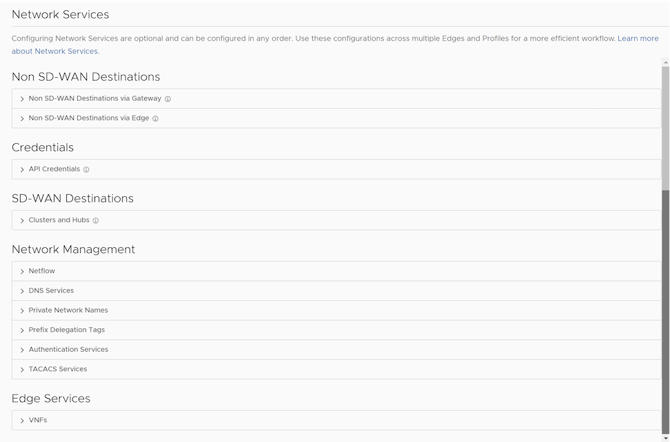

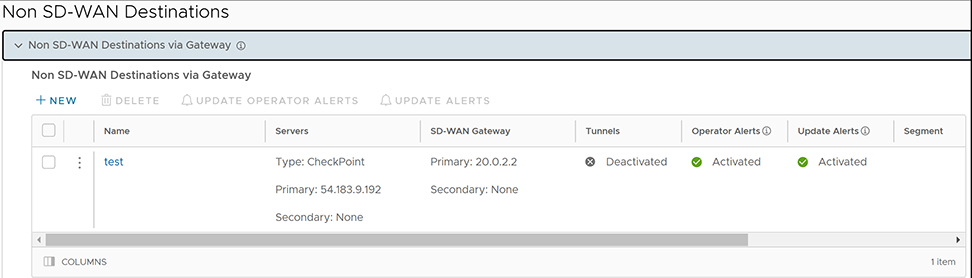
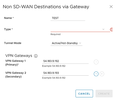
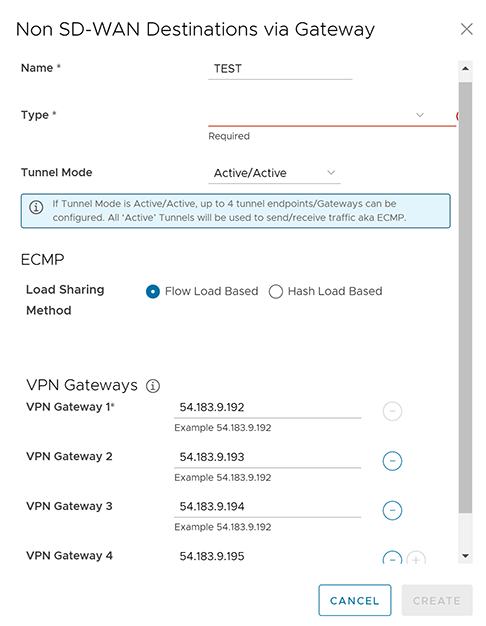
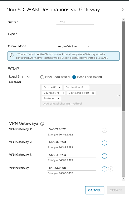
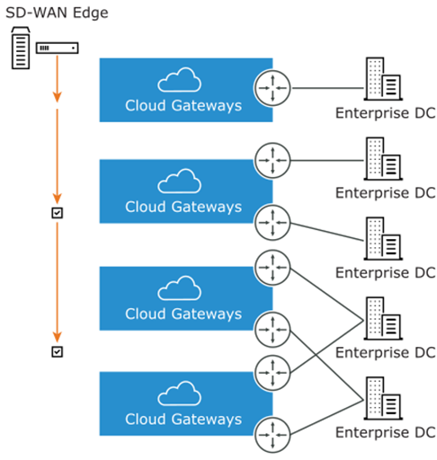
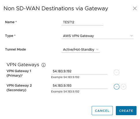
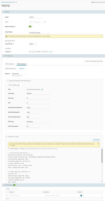
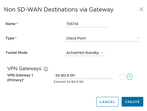
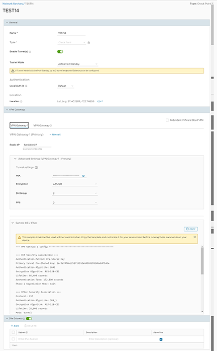
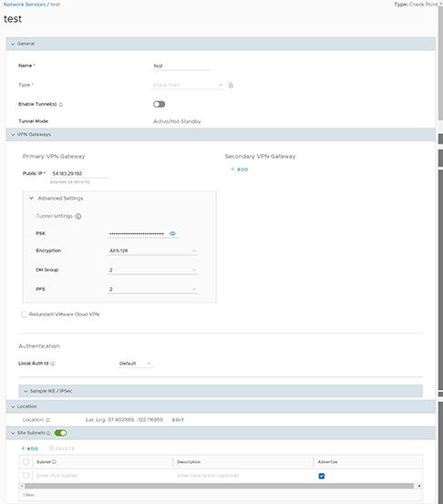
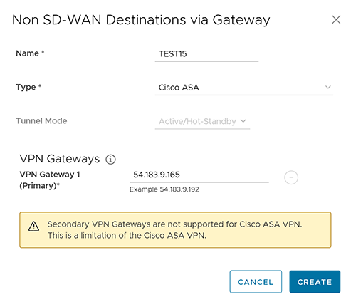
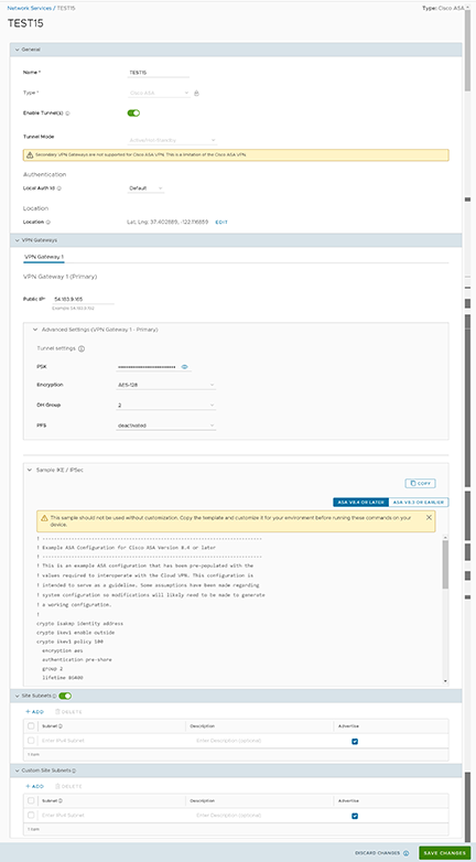
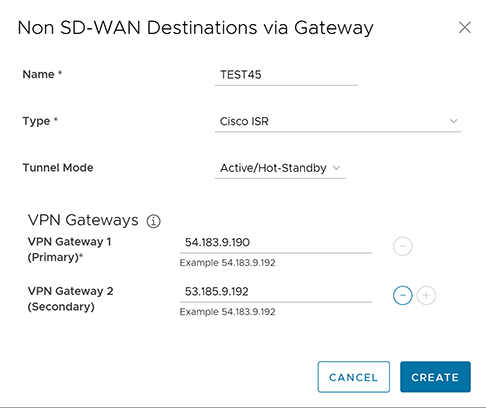
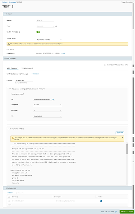
_NSD.png)
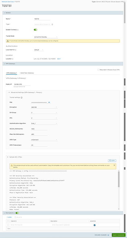
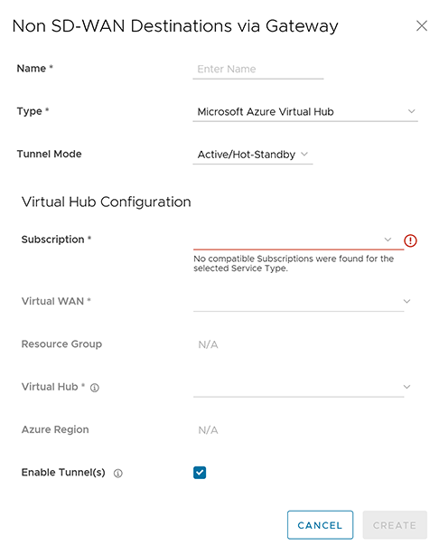
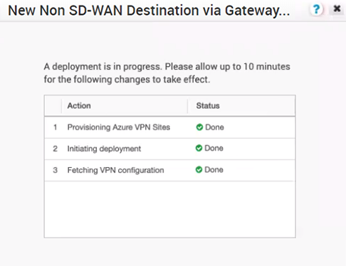 Once the Azure VPN sites provision at the Orchestrator side, users can view the VPN sites (Primary and Redundant) in the Azure portal by navigating to Virtual WAN Virtual WAN architecture VPN sites.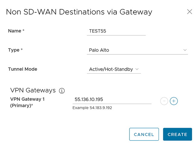
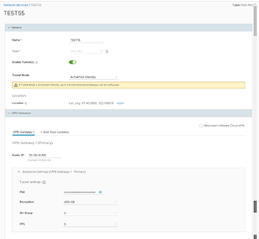
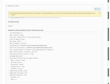
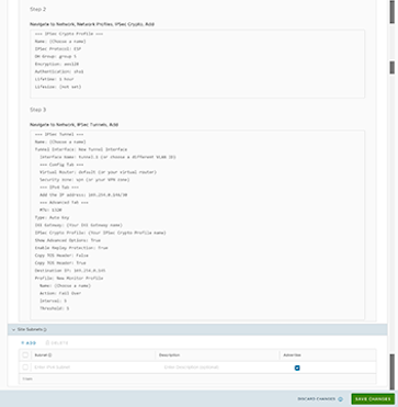
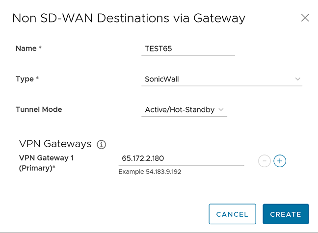
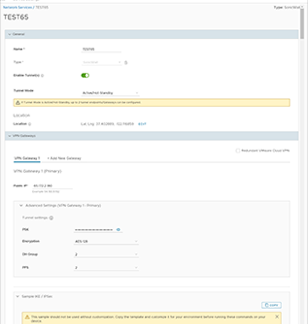
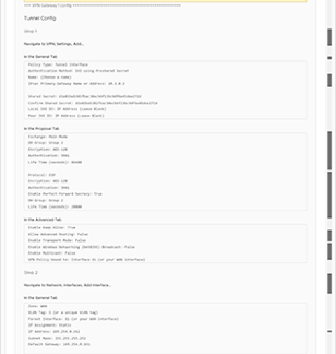
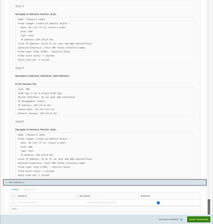
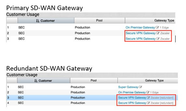


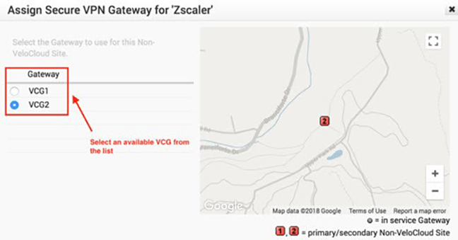
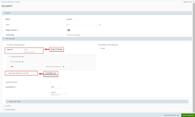
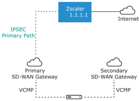
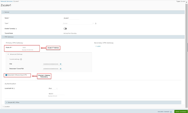
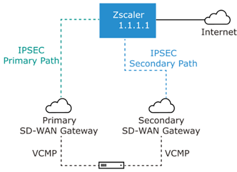
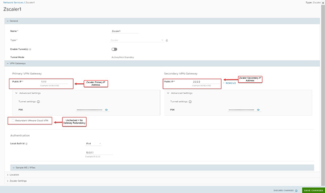
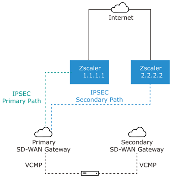
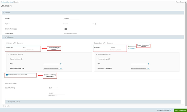
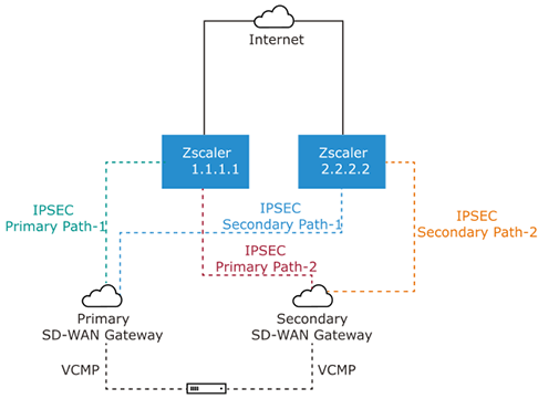
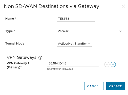
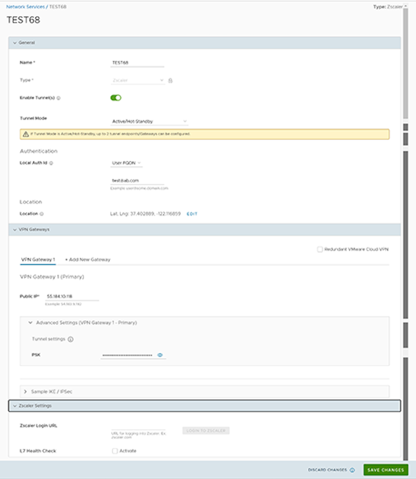
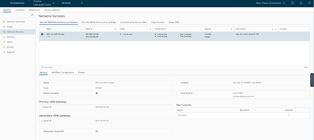

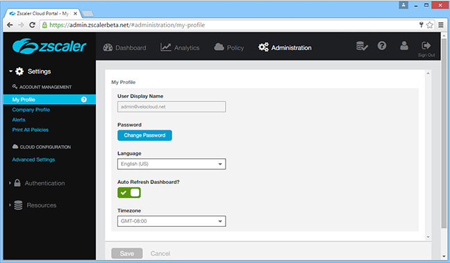
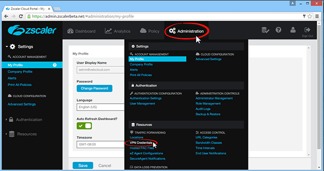

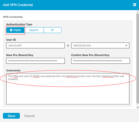

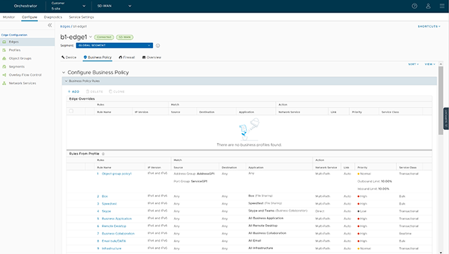
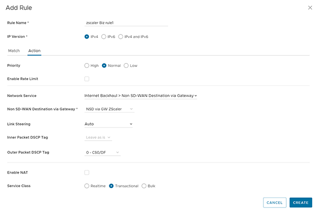
_NSD.png)
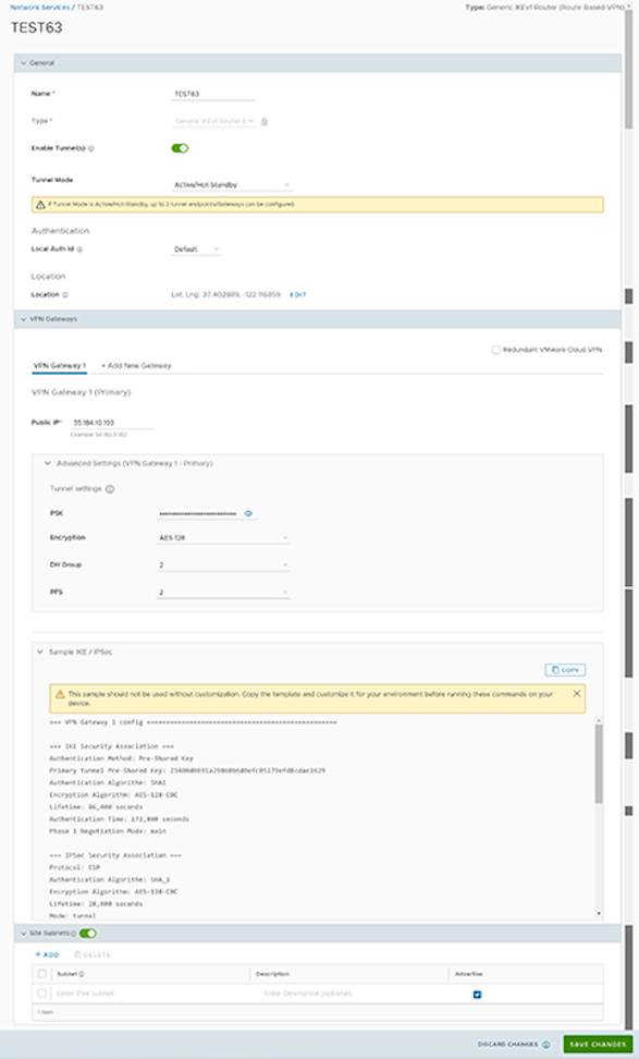
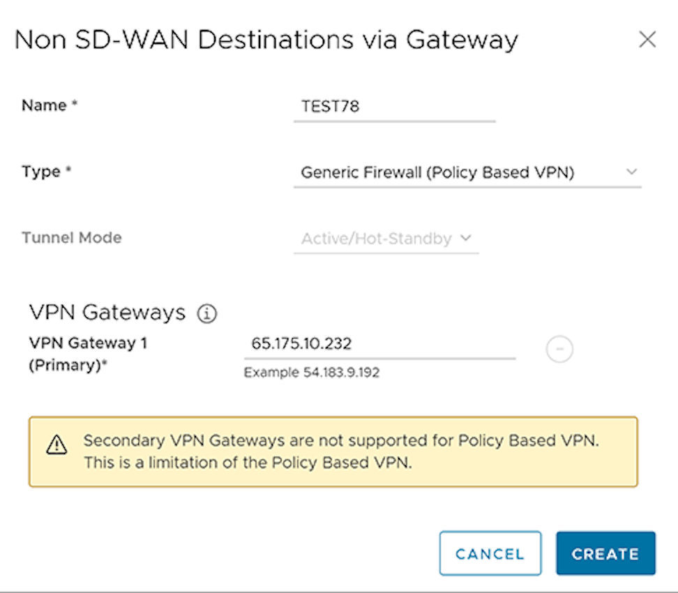
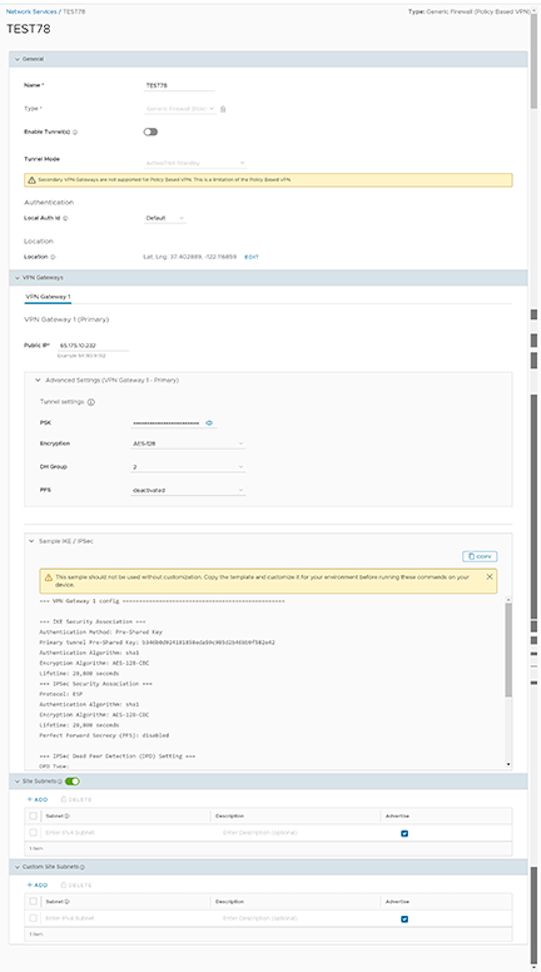 Note: The Generic Firewall (Policy Based VPN) does not support a Secondary VPN Gateway.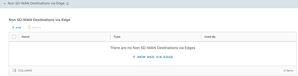
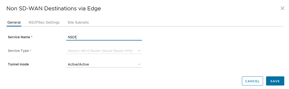

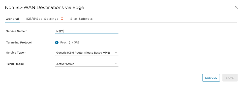
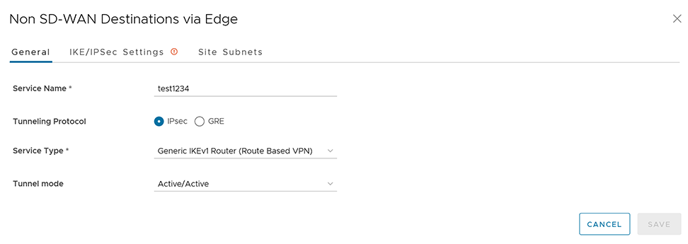
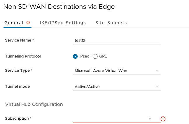

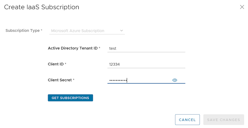
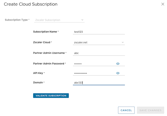
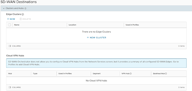
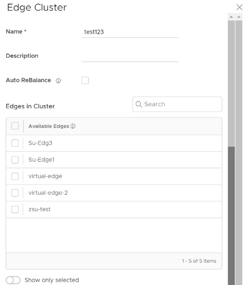
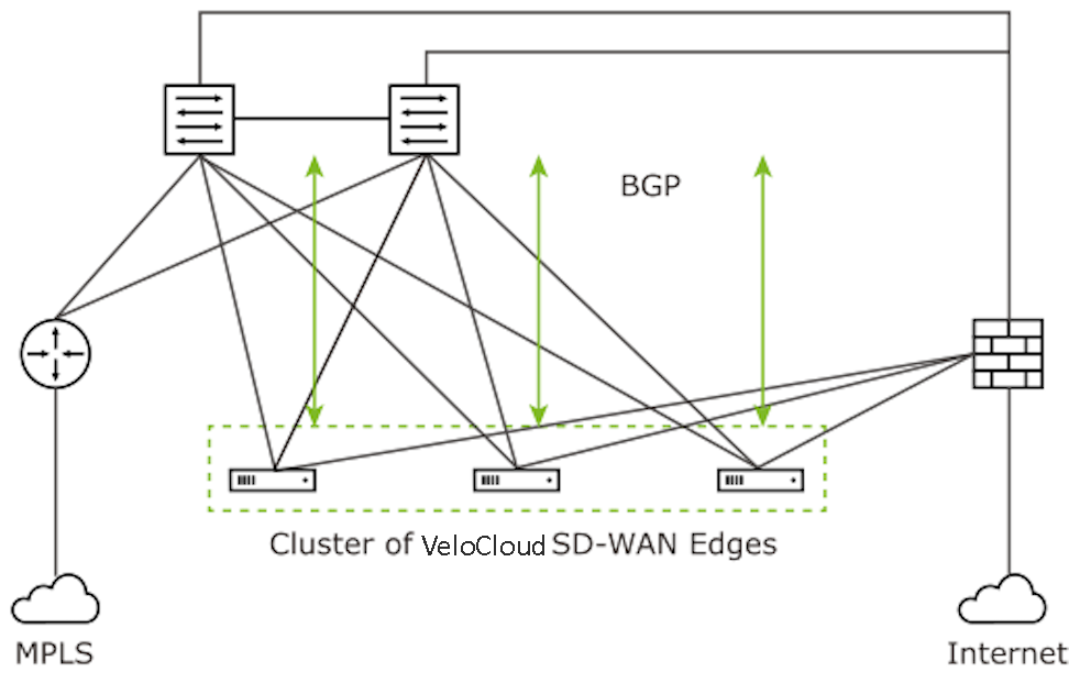
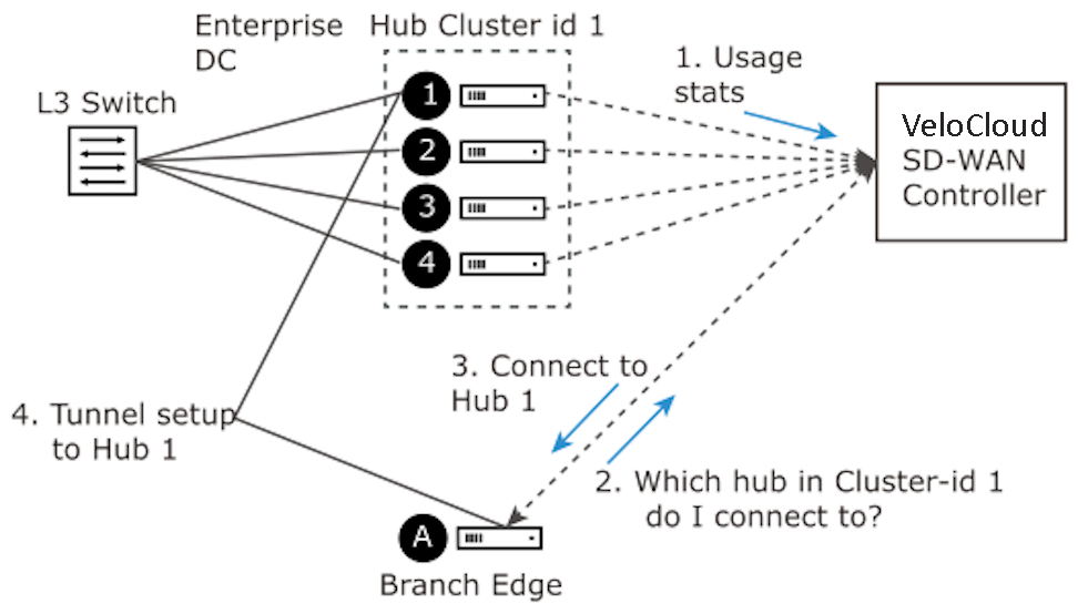
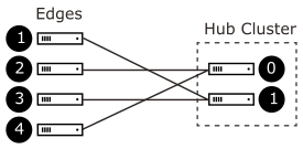
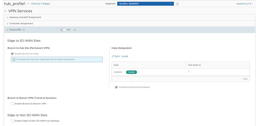
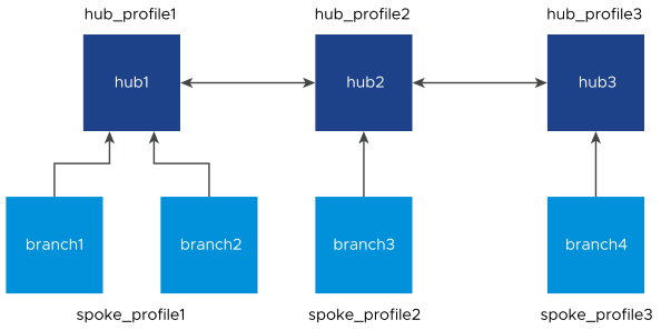
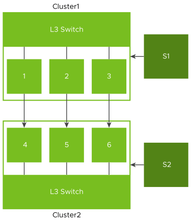
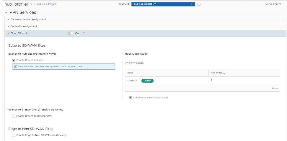
 Perform the Hub and Cluster Interconnect configurations only at the Profile level to activate the feature and create a tunnel between the Hub Clusters, which allows the respective Spoke Edges to communicate with each other. Activating or deactivating the Hub or Cluster Interconnect feature causes all Edge devices associated with the Profile to restart. Hence, Arista recommends configuring the feature only in maintenance mode to prevent disruptions to traffic.