Setup Preparation
Site Selection
Before you begin, read the safety instructions in your Safety, Environmental, and Regulatory Information booklet.
- Before you begin, review the safety instructions located at https://www.arista.com/en/support/product-documentation.
- Begin installing the rails in the allotted space closest to the bottom of the rack enclosure.
- Other Requirements: Select a site where liquids or objects cannot fall onto the equipment and foreign objects are not drawn into the ventilation holes. Verify these guidelines are met:
- Clearance areas to the front and rear panels allow for unrestricted cabling.
- All front and rear panel indicators can be easily read.
- Power cords can reach from the power outlet to the connector on the rear panel.
Receiving and Inspecting the Equipment
Upon receiving the appliance, inspect the shipping boxes and record any external damage. Retain packing materials if you suspect that part of the shipment is damaged; the carrier may need to inspect them.
If the boxes were not damaged in transit, unpack them carefully. Ensure you do not discard any accessories packaged in the same box as the main unit.
Inspect the packing list and confirm that you received all listed items. Compare the packing list with your purchase order. The Appendix provides a list of components included with the appliance.
Electrostatic Discharge (ESD) Precautions
Adhere to these guidelines to avoid ESD damage when installing or servicing the appliance.
- Assemble or disassemble equipment only in a static-free work area.
- Select a conductive work surface (such as an anti-static mat) that dissipates static charge.
- Wear a conductive wrist strap to dissipate static charge accumulation.
- Minimize handling of assemblies and components.
- Keep replacement parts in their original static-free packaging.
- Remove all plastic, foam, vinyl, paper, and other static-generating materials from the work area.
- Select tools that do not create ESD.
Setting up Your System
Complete the following steps to set up your system:
CloudVision AGNI Appliance Setup
- Key to the system key lock.
- #1 and #2 Phillips screwdriver.
- Wrist grounding strap connected to ground.
- The rack mount kit instructions are located in the shipping box.
Before Working Inside your System
- Turn off the system, including all attached peripherals.
- Disconnect the system from the electrical outlet and disconnect the peripherals.
- Remove the system cover.
Front Bezel
Complete the following tasks to remove the front bezel.
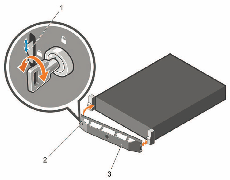
- Unlock the key lock at the left end of the bezel.
- Lift the release latch next to the key lock.
- Rotate the left end of the bezel away from the front panel.
- Unhook the right end of the bezel and pull the bezel away from the system.
Locate the MAC Addresses for the AGNI Appliance
The information tag is a slide-out label that contains system information such as Service Tag, NIC, and MAC address for your reference. Record the MAC addresses in the CloudVision Worksheet.

| 1 | Information tag (front view) | 2 | Information tag (back view) | 3 | OpenManage Mobile (OMM) label |
| 4 | iDRAC MAC address and iDRAC secure password label | 5 | Service Tag |
Rear Panel Ethernet Connections
On the back panel of the CloudVision AGNI appliance, locate the Ethernet Integrated 10/100/1000 Mbps NIC connectors.
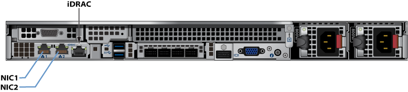
iDRAC is an Intelligent Platform Management Interface (IPMI) that provides a GUI-based out-of-band interface for monitoring the hardware appliance.
Record the IP address and Host name information on the CloudVision AGNI Worksheet.
DNS Entries
- Each of the CloudVision AGNI Appliance host machines.
- Each of the CloudVision AGNI Appliance iDRAC interfaces.
Contact your DNS zone administrator for assistance.
CloudVision AGNI Appliance IP Configuration
The CloudVision AGNI Appliance Host and iDRAC IP addresses are allocated in either of two ways:
- DHCP Based IP Address Setup Setting up Manual IP Address.
- Web Access into Host via iDRAC Web Access into iDRAC (System IPMI).
- Manual IP Address Setup Setting up Manual IP Address.
- Web Access into Host via iDRAC Web Access into iDRAC (System IPMI).
Setting up Manual IP Address
To setup manual IP address:
- Press <F2> during the Power-on Self-test (POST).
Figure 4. Power-On Self-Test 
- In the System Setup Main Menu, click iDRAC Settings.
Figure 5. System Setup Main Menu 
The iDRAC Settings page is displayed.
- Click Network.
Figure 6. iDRAC Settings page 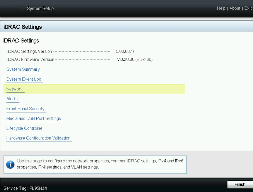
The Network page is displayed.
Figure 7. iDRAC Settings Network 
Scroll down in the iDRAC Settings Network page to the Common Settings section.
- Configure the IPv4 Settings:
Figure 8. iDRAC Settings: Common & IPv4 Settings 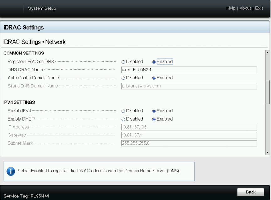
- Click the Finish button. The Save Changes pop-up window is displayed:
Figure 9. Save Changes Window 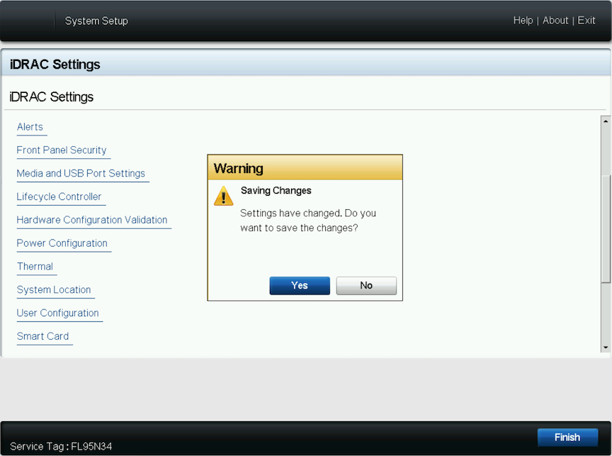
- Click the Yes button to save the changes. The network information is saved, and the system reboots.
Figure 10. Save Settings window 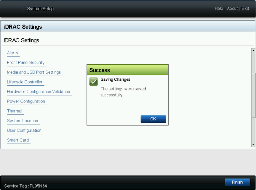 Note:
Note:Direct IP Address Setup requires a terminal connected to the appliance's VGA port.
This section is skipped if the Host and iDRAC IP addresses are configured with a DHCP server.