Preparation
Site Selection
Read the safety instructions in your Safety, Environmental, and Regulatory Information booklet before you begin.
- Before you begin, review the safety instructions located at https://www.arista.com/en/support/product-documentation.
- Begin installing the rails in the allotted space that is closest to the bottom of the rack enclosure.
- Other Requirements: Select a site where liquids or objects cannot fall onto the equipment and foreign objects are not drawn into the ventilation holes. Verify these guidelines are met:
- Clearance areas to the front and rear panels allow for unrestricted cabling.
- All front and rear panel indicators can be easily read.
- Power cords can reach from the power outlet to the connector on the rear panel.
Electrostatic Discharge (ESD) Precautions
- Assemble or disassemble equipment only in a static-free work area.
- Use a conductive work surface (such as an anti-static mat) to dissipate static charge.
- Wear a conductive wrist strap to dissipate static charge accumulation.
- Minimize handling of assemblies and components.
- Keep replacement parts in their original static-free packaging.
- Remove all plastic, foam, vinyl, paper, and other static-generating materials from the work area.
- Select tools that do not create ESD.
CloudVision Physical Appliance Setup
- Key to the system key lock.
- #1 and #2 Phillips screwdriver.
- Wrist grounding strap connected to ground.
- Rack mount kit instructions located in the shipping box.
Front Bezel
Removing the front bezel:
- Unhook the right end of the bezel and pull the bezel away from the system.
Figure 1. Removing and Installing the Front Bezel
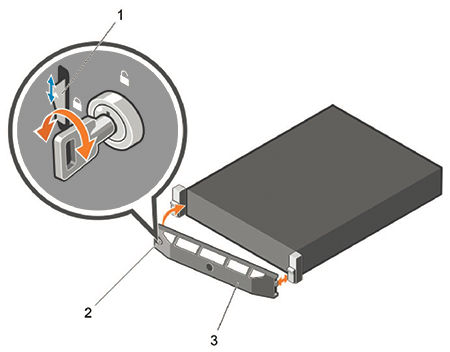
1 Release Latch 2 Key lock 3 Front Bezel
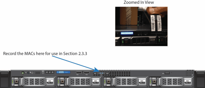
Locate the MAC Addresses for the CloudVision Appliance
The information tag is a slide-out label that contains system information such as Service Tag, NIC, and MAC address for your reference. Record the MAC addresses on the CloudVision Worksheet.
Back Panel Ethernet Connections
On the back panel of the DCA-CV-100 CloudVision appliance, locate the Ethernet Integrated 10/100/1000 Mbps NIC connectors.
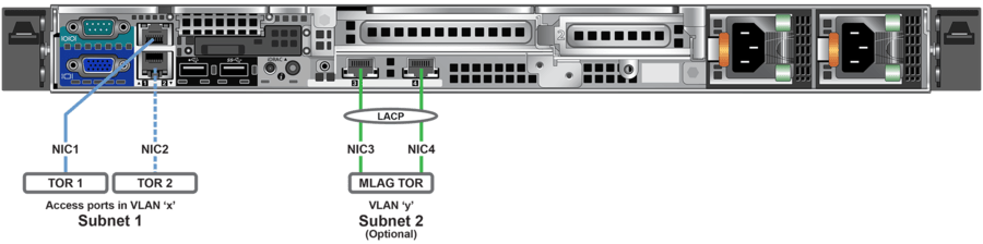
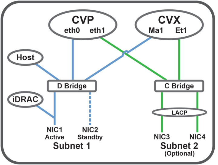
iDRAC is an Intelligent Platform Management Interface (IPMI) that provides a GUI-based out-of-band interface for monitoring the hardware appliance. iDRAC uses NIC1 (see Figure 2-4) for its network connectivity using a unique MAC address.
Record the IP address and Hostname information on the CloudVision Worksheet (see Appendix H).
DNS Entries
- Each of the CloudVision Appliance host machines.
- Each of the CloudVision Appliance iDRAC interfaces.
- Each of the CloudVision Portal (CVP) nodes.
- Each of the CloudVision Server (CVX) nodes.
Contact your DNS zone administrator for assistance.
CloudVision Appliance IP Configuration
The CloudVision Appliance Host and iDRAC IP addresses can be allocated in one of two ways:
DHCP Based IP Address Setup
iDRAC IP Address
Using the iDRAC MAC from Locate the MAC Addresses for the CloudVision Appliance (see Figure 2 - MAC Address Location), input an entry into the DHCP Server for the corresponding iDRAC IP address mapping to that MAC.
Host IP Address
Using the HOST NIC1 MAC from Locate the MAC Addresses for the CloudVision Appliance (see Figure 2 - MAC Address Location), input an entry into the DHCP Server for the corresponding HOST IP address mapping to that MAC.
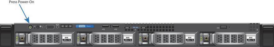
Turn the system on by pressing the power button on the front of the system.
Manual IP Address Setup
iDRAC IP Address
The iDRAC IP address can be manually configured via the host's bash shell using the racadm tool. The racadm commands below are sequence dependent and must be entered in the following order.
Host IP Address
The host IP address can be manually configured via the host's bash shell. For the settings to be persistent, the following configuration must be completed.