Powering the Modular Switch
Installation of this equipment must comply with local and national electrical codes. Consult with the appropriate regulatory agencies and inspection authorities to ensure compliance if necessary.
Installation de cet équipement doit être conformes aux codes électriques locaux et nationaux. Si nécessaire, consulter les organismes de réglementation appropriés et des autorités de contrôle pour assurer la conformité.
The switch operates with multiple power supplies. Refer to Specifications for information regarding your specific system. The Table 1 - Power Supply Capacity and Requirements for 7300 Series Modular Switches list the nyumber of modules each chassis can contain and the minimum operating requirements for each model.
| Switch Model | Chassis Capacity | Minimum Operating Requirements |
|---|---|---|
| DCS-7304
DCS-7324 DCS-7304X3 |
Front Panel: 4 | 1 active circuit |
| DCS-7308
DCS-7328 DCS-7308X3 |
Front Panel: 6 modules | 2 active circuits |
| DCS-7316 | Front Panel: 6 modules Rear Panel: 2 modules | 3 active circuits |
The Front Panels display the power supplies' location on the switch's front panel. The Rear Panels display the location of power supplies on the rear panel of DCS-7316 switches.
Read all installation instructions before connecting the system to the power source.
Lire toutes les instructions d'installation avant de brancher le système à la source d'alimentation.
- Non-Redundant Configuration: Provide power to the minimum required power inputs.
- Redundant Power Supply Configuration: Connecting power to modules in excess of minimum requirements protects the switch against failed modules and can provide grid-level redundancy.
- Power down the Switch: Remove all power cords from the power input sockets.
Important:
This equipment must be grounded. Never defeat the ground conductor. This unit requires over-current protection.
Cet équipement doit être mis à la terre. Ne jamais modifier le conducteur de terre. Cet appareil nécessite de protection contre les surintensités.
Cabling the AC Power Supply
Grounding the Switch
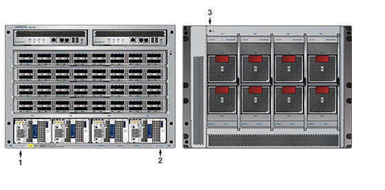
After mounting the switch into the rack, connect the switch to the data center ground. Figure 1 - Grounding Pad and ESD Grounding Pad Sockets display the grounding pads' location on the front panel (left illustration) and rear panel (right illustration). After the switch is grounded, ESD wrist straps can be grounded by connecting them to one of the grounding pads.
Grounding wires and grounding lugs (M4 x 0.7) are not supplied. Wire size should meet local and national installation requirements. Commercially available 6 AWG wire is recommended for installations in the U.S.
À la terre et de mise à la terre fils cosses (M4 x 0.7) ne sont pas fournis. Calibre des fils doit satisfaire des exigences de l’installation locale et nationale. Disponible dans le commerce des câbles 6 AWG sont recommandé pour les installations aux États-Unis.

| 1 | Secondary ground | 2 | Secondary ground | 3 | Earth grounding pad |
Connecting Power Cables to an AC Power Supply
The Figure 2 - Power Input Sockets display an AC power supply module, including the power input socket.
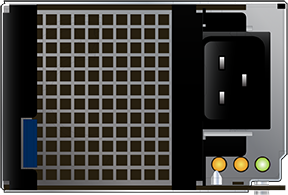
The power supplies require power cables that comply with the IEC-320 C19 plug. The accessory kit provides 14 AWG and C19 to C20 power cables.
- Pull the retaining clip back on each power input socket.
Note: The retaining clip is optional (if provided).
- Plug the power cables into the sockets.
- Adjust the retaining clips for your power cords (if a retaining clip was provided).
- Push the retaining clip back down over the cable (if retaining clip was provided).
Cabling the DC Power Supply
The Figure 3 - Secondary Ground Pads display the location of the secondary grounding pads on the front panel (left illustration) of the switch chassis. After mounting the switch into the rack, connect at least one of the secondary grounds to the data center ground. After the switch is grounded, ESD wrist straps can be grounded by connecting them to one of the attach points.
Grounding wires and grounding lugs (M4 x 0.7) are not supplied. Wire size should meet local and national installation requirements. Commercially available 4 AWG wire is recommended for installations in the U.S.
À la terre et de mise à la terre fils cosses (M4 x 0.7) ne sont pas fournis. Calibre des fils doit satisfaire des exigences de l’installation locale et nationale. Disponible dans le commerce des câbles 4 AWG sont recommandé pour les installations aux États-Unis.
The -48V and Battery-Return leads are a pair and should run adjacent and be approximately the same length.
Le - 48V et câbles de batterie-retour sont une paire courir à côté de l'autre et doivent être à peu près la même longueur.
DC Power Supplies
The 7300 Series chassis supports two DC power supplies (Figure 4-4). Only specified power supplies are available for use in a particular switch configuration.
-
PWR-2700-DC-R (Figure 8 - PWR-2700-DC-R Power Supply).
-
PWR-3K-DC-Blue is also referred to as PWR-3K-DC-F (Figure 7 - PWR-3K-DC-Blue Power Supply).
Figure 3. Secondary Ground Pads
1
Secondary ground
2 Secondary ground 3 Earth grounding pad Note: Your device's power supply orientation may differ from the one shown in Figure 4 - PWR-3K-DC-Blue and PWR-2700-DC-R Power Supplies.Figure 4. PWR-3K-DC-Blue and PWR-2700-DC-R Power Supplies
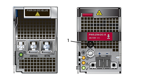
1
Primary ground
-
Wire and Lug Preparation
- Stranded copper wiring is required.
- Commercially available 2 to 4 AWG wire is recommended for installations in the U.S.
- Wire size should meet local and national installation requirements.
- Grounding wires and grounding lugs are not supplied.
- Strip the wires to the appropriate length for the lugs.
The wires connecting the DC power supply to the power source must meet the following requirements:- DC Input Wire Size: 2 – 4 AWG (33.6 mm2 to 21.2 mm2).
- Primary Ground Wire Size: 2 – 4 AWG (33.6 mm2 to 21.2 mm2) per power supply.
- The conductors are copper.
Figure 5. Lugs Wiring Terminations
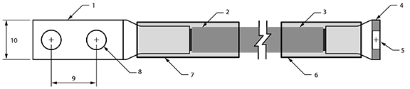
1 -48V + RTN lug 5 5/16” 9 5/8” 2 Insulated wire 6 Heat-shrink tubing 10 1/2” 3 Insulated wire 7 Heat-shrink tubing 4 Ground lug (right angle) 8 1/4” Figure 6. Ground Lug Wiring Termination (PWR-2700W-DC-R)
.png)
1 Insulated wire 3 5/16” 2 Ground lug (right angle) 4 Heat-shrink tubing Note: You can also use a 45° angled connector instead of the straight connector shown.
- Select agency-approved compression (pressure) lugs for wiring terminations with a single 5/16" mounting hole. Two-hole lugs should have 1/4" mounting holes on 5/8" centers.
The PWR-2700W-DC-R ground lug is a right-angle lug. Check the terminations for the appropriate wire size. Use a ground wire of at least 2 – 4 AWG. Use only copper wire.
- Slip on heat-shrink tubing on the wire ends before assembling the lugs onto the wire.
- The lugs must be crimped with the proper tool.
- The tubing should extend over the lug’s barrel and the wire's insulator.
- Shrink the tubing with a heat gun.
PWR-3K-DC-Blue Power Supply
Figure 7 - PWR-3K-DC-Blue Power Supply displays the PWR-3K-DC-Blue power supply.
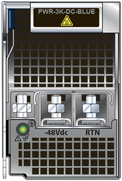
- Prepare the stranded wiring; see Wire and Lug Preparation.
- Attach the power cable to the supply terminals.
- Tightening Torque: 2.7 N-m (24 in.-lbs.)
DC Power Adapter Installation for PWR-2700-DC-R
Connecting the Power Cable Lug to the Terminal Studs
- Prepare the stranded wiring; see Wire and Lug Preparation.
- Remove the clear plastic cover protecting the terminal studs on the adapter by lifting the small center tab while sliding the cover off the adapter.
Connecting the Ground to PWR-2700-DC-R Power Supply
The primary ground on the system requires a 2 – 4 AWG 5/16 inch lug per power supply.
Figure 8 - PWR-2700-DC-R Power Supply displays the PWR-2700-DC-R power supply without the DC adapter.
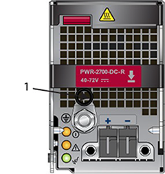
| 1 | Primary ground |
- Prepare the stranded wiring; see Wire and Lug Preparation.
- Attach the ground cable to the ground stud.
- Tightening Torque: 2.7 N-m (24 in.-lbs.).