Rack Mounting the Switch
The rack mounting procedure is identical for all modular switches. Illustrations in this chapter depict the mounting of an unpopulated DCS-7304 chassis.
Les procédure de montage du bâti est identique pour tous les commutateurs modulaires. Illustrations dans ce chapitre montrent le montage d’un châssis de DCS-7304 inhabité.
- Two-Post Rack Mount provides instructions for mounting the switch in a two-post rack.
- Four-Post Rack Mount provides instructions for mounting the switch in a four-post rack.
After completing the instructions for your rack type, proceed to Powering the Modular Switch.
Two-Post Rack Mount
To mount the switch to a two-post rack, assemble mounting brackets to the middle of the chassis, then attach the brackets to the rack.
Two-post rack mount parts are only available through your sales representative. Two-post rack mounting is not supported for DCS-7316 switches.
Pièces de montage rack à deux montants sont uniquement disponibles par l’intermédiaire de votre représentant des ventes. Montage en rack de deux-poteau n’est pas supporté pour les commutateurs DCS-7316.
- 2 center-mount brackets.
- 16 (DCS-7304) or 20 (DCS-7308) M4x8 panhead Phillips screws.
Attaching Mounting Brackets to the Chassis
- Orient the switch chassis and the two center-mount brackets (Figure 1 - Attaching the Center-mount Brackets).
Figure 1. Attaching the Center-mount Brackets
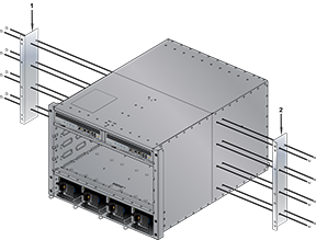
Position the flanges that attach to the rack posts toward the front of the chassis.
- Attach both center-mount brackets to the chassis with the provided M4x8 panhead Phillips screws. Secure the bracket by attaching screws through each bracket hole.
Inserting the Switch into the Rack
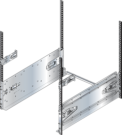
- Rotate the stabilizer bar from the left shelf toward the right shelf such that the nob at the end of the stabilizer bar inserts into the notch at the rear of the ledge of the right shelf.
Figure 2. Both Switch Shelves Installed
- Move the chassis to the rack using a mechanical lift (Figure 3 - Lifting the Switch ChassisLifting the Switch Chassis). If modules are inserted in the chassis, use the lift carefully to avoid damaging any components.
Figure 3. Lifting the Switch Chassis
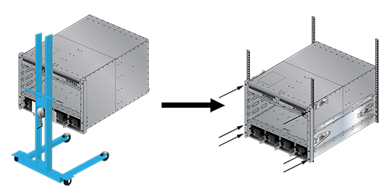
- Lift the chassis into the rack.
- Secure the chassis by tightening the six thumbscrews on the front flanges into the rack posts.
After completing the Four-Post Installation, proceed to Powering the Modular Switch.
Four-Post Rack Mount
The switch is mounted onto a four-post rack by assembling a shelf into the rack and then attaching the switch to the shelf.
Component Description
- 1 Left Shelf and 1 Right Shelf (Shelves)
-
2 Mounting Ears (Mounting Ears)
Note: Components are designed for tool-less installation in square-hole racks. To install the switch in round hole or threaded hole racks, remove all rack plugs from the rail kit, if required (described below), and attach all components with nuts and bolts that fit the rack.
The finished assembly for rack mounting the device is shown in the Figure 5 - Left Shelf – Inner View. Detailed mounting instructions for all rack types start from Shelf Installation.
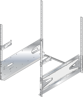
Shelves
The two shelves are almost identical, differing in that 1) they are mirror images of each other and 2) the left shelf includes a stabilizer bar. Each shelf has a two-piece mechanism. The base includes the surface upon which the switch is placed and is oriented towards the front of the rack. The slide-end adjusts the shelf’s length to fit the shelf between the front and rear posts of various size racks.
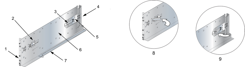
| 1 | Front post attachments | 4 | Rear post attachments | 7 | Stabilizer bar (left shelf only) |
| 2 | Front latch (closed) | 5 | Slide-end | 8 | Front latch (open) |
| 3 | Rear latch (closed) | 6 | Base
|
9 | Rear latch (open) |
Figure 6 - Right Shelf – Outer View displays the outside view of the right shelf, from where rack plugs and guide pins that insert into rack posts are visible (Insets A and B). To install shelves into posts with threaded or rounded holes, attach the shelves with bolts that fit the rack. Remove all plugs from the shelves if present.
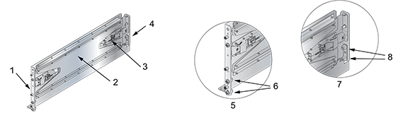
| 1 | Front post attachments (Inset A) | 4 | Rear post attachments (Inset B) | 7 | Inset B |
| 2 | Base | 5 | Inset A | 8 | Rack plugs |
| 3 | Slide-end | 6 | Rack plugs |
Mounting Ears
Figure 7 - Mounting Ears displays the mounting ears, securing the rack's switch top. The two mounting ears are identical and installed above each shelf. The inner side of each ear may include a latch to the locking mechanism that secures the ear to the rack.
Rack posts and guide pins inserted into the rack are visible from the outer side of the ear (Inset B). To install ears into posts with threaded or round holes, remove both plugs from each ear (if required for rail set), then install the ears with screws that fit the rack.
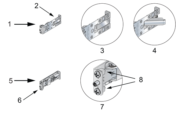
| 1 | Brace (Inner view) | 4 | Inset A - Released | 7 | Inset B (Details) |
| 2 | Inset A | 5 | Brace (Outer view) | 8 | Rack plugs |
| 3 | Inset A - Locked | 6 | Inset B |
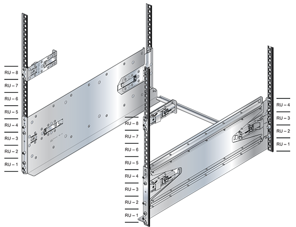
Component Placement
- 7304: 8th RU (22nd through 24th holes)
- 7308: 13th RU (37th through 39th holes)
- 7316: 21st RU (61st through 63rd holes)
Figure 8. Component Placement
Switch Mounting Process
- Installing the shelves.
- Installing the mounting ears.
- Placing and securing the switch upon the shelves.
Shelf Installation
The installation process for each shelf is identical. The shelves must be installed on the same horizontal level. In the following section, inner side illustrations feature the left shelf, and outer side illustrations feature the right shelf.
- If applicable, verify that both locking mechanism latches on the shelf are open (Figure 5 - Left Shelf – Inner View, insets A and B). For racks that do not require the locking mechanism, skip to Step 2.
- Attach the front side of the shelf to its corresponding front rack post by inserting the shelf-side rack plugs and guide pins into post slots (Figure 9 - Attaching the Right Shelf).
The shelf ledge must be between the front posts. If the rack plugs were previously removed or not present, use bolts to attach the shelf to the rack and skip to Step 4.
Figure 9. Attaching the Right Shelf
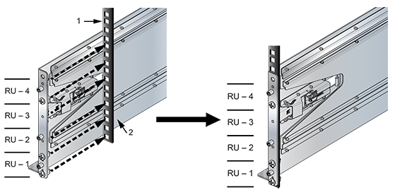
1 Right front rack post 2 Right shelf - Close the front locking mechanism latch (Figure 6 - Right Shelf – Outer View).
- Glide the slide-end to a position outside its rear rack post (Figure 10 - Adjusting the Right Shelf).
Figure 10. Adjusting the Right Shelf
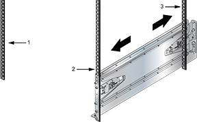
1 Front left rack post 2 Front right rack post 3 Rear right rack post - Attach the back side of the shelf into the rear shelf by gliding the slide-end so that the rack plugs (if present) and guide pins are inserted to the rack post holes (Figure 11 - Seating the Left Shelf).
The bottom rack plug must be inserted one RU (three rack holes) above the bottom rack plug on the front side of the shelf. If the locking mechanism and plugs are not used, fasten the back side of the shelf to the rear shelf and skip to Step 6.
Figure 11. Seating the Left Shelf
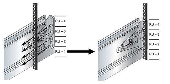
- Close the rear locking mechanism latch if present (Figure 6 - Right Shelf – Outer View).
Mounting Ear Installation
The mounting ears attach the top of the switch to the rack posts. Their placement on the posts depends on the switch model (Component Placement).
The installation process for each mounting ear is identical. The inner side of the mounting ear (which includes the locking mechanism latch) is oriented between the front rack posts. Depending on the rack kit configuration, a locking mechanism may not be present. In the following section, all illustrations feature the right mounting ear.
- Install the mounting ear on the front post by inserting the front rack plugs (if present) and guide pins in the racks specified for the switch model that is being installed (Figure 12 - Attaching the Right Mounting Ear).
Figure 12. Attaching the Right Mounting Ear
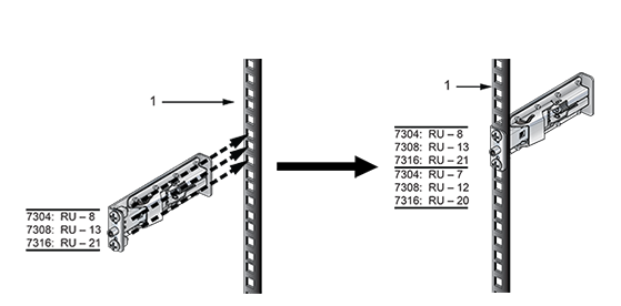
1 Front right rack post If rack plugs are not present, align the threaded holes and attach the mounting ears with screws.
- If applicable, close the front locking mechanism latch (Figure 7 - Mounting Ears).
Inserting the Switch into the Rack
- Rotate the stabilizer bar from the left shelf toward the right shelf such that the nob at the end of the stabilizer bar inserts into the notch at the rear of the ledge of the right shelf.
Figure 13. Both Switch Shelves Installed
- Move the chassis to the rack using a mechanical lift (Figure 3 - Lifting the Switch ChassisLifting the Switch Chassis). If modules are inserted in the chassis, use the lift carefully to avoid damaging any components.
Figure 14. Lifting the Switch Chassis
- Lift the chassis into the rack.
- Secure the chassis by tightening the six thumbscrews on the front flanges into the rack posts.
After completing the Four-Post Installation, proceed to Powering the Modular Switch.