Fabric and Fan-only Module Description
Each switch has four rear slots for fabric modules. In addition to providing the data transport media, fabric modules contain fan modules that circulate air through the switch. Proper switch operation requires the population of each rear slot.
Switches are configured for maximum traffic capacity and contain a fabric module in each rear slot. In network configurations that do not require maximum traffic capacity, an economical alternative is to replace two fabric modules with fan-only modules.
Each fan-only module provides the cooling capacity of the corresponding fabric module through a set of fans integrated into the module. The fans of a fan-only module are not removable, unlike the fabric module that requires the insertion of individual fan modules.
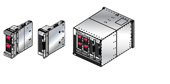
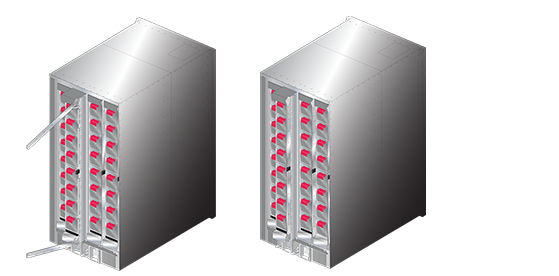
Fan-only modules are available for the 7304 and 7308 switches. Fabric and Fan Modules: Extracted-left displays a 7304 fabric module and a 7304 fan-only module that is removed from the switch. Fabric and Fan Modules: Installed-right displays the rear panel of a 7304 switch that contains two fabric modules and two fan-only modules.
Each module includes lock levers that secure it to the chassis. The module and the lock levers are easily damaged by improperly removing, inserting, or handling the fabric module. Never use the lock levers to lift or move the module after it is removed from the chassis.
The color of the fan modules specifies the fan direction of the fabric modules. The fan direction on fan-only modules is denoted by the indicator located below the top handle (Figure 5 - DCS-7304 Fabric and Fan-only Module (left); DCS-7304 Fan-only Module (right)).
The following module combinations are the only valid rear panel configurations:
- Fabric Modules in slots 1 – 4
-
Fabric Modules in slots 1 – 2; Fan-only modules in slots 3 – 4.
Note: On the 7308, if a fan-only module is not inserted, a metal piece covers the slot, as shown below.
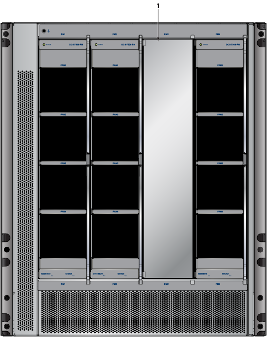
1 Metal covering
Part Numbers
Table 1 - Fabric and Fan-only Module Part Numbers lists the part numbers of Fabric and Fan-only Modules.
| Switch Model | Fabric Module | Fan-only Module |
|---|---|---|
| DCS-7304 (Air Inlet)
DCS-7304 (Air Exit) |
DCS-7304X-FM-R
DCS-7304X-FM-F |
DCS-7304-S-FAN-R
DCS-7304-S-FAN-F |
| DCS-7308 (Air Inlet)
DCS-7308 (Air Exit) |
DCS-7308X-FM-F
DCS-7308X-FM-R |
DCS-7308-S-FAN-R
DCS-7308-S-FAN-F |
| DCS-7316 (Air Inlet)
DCS-7316 (Air Exit) |
DCS-7316X-FM-F
DCS-7316X-FM-R |
Not Available
Not Available |
| DCS-7324 (Air Exit Only) | DCS-7324-FM-F | Not Supported |
| DCS-7328 (Air Exit Only | DCS-7328-FM-F | Not Supported |
Handling Fabric Modules
Figure 2 - Locking Mechanism: DCS-7316 Fabric depicts a DCS-7316 chassis with the inner two fabric modules installed. Lock levers are shown in the open and closed position, along with the button that releases them into the open position. The lock levers are in the closed position when the switch is in service.
| 1 | Lock levers open (FM2) | 3 | Release button (FM3) |
| 2 | Upper lock lever closed (FM3) | 4 | Lower lock lever closed (FM3) |
These sections describe fabric module handling procedures. Illustrations depict a DCS-7316 chassis and fabric modules. While proper handling of DCS-7316 components is imperative because of their size and weight, the instructions also describe best practices for handling DCS-7304 and DCS-7308 components.
Removing Fabric Modules
This procedure removes a fabric from the switch chassis.
- Grasp the module frame and pull it until it is completely outside the chassis.
Figure 3. Fabric Module Removal: Initial Position and Opening the Lock-Levers
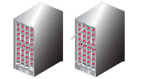
Figure 4. Fabric Module Removal: Edging the Module Out and Closing the Lock-Levers
The DCS-7316 fabric module is almost three feet long and weighs close to 40 pounds. Use necessary precautions to safely manage the component outside of the chassis.
Inserting Fabric Modules
The fabric module insertion process is the inverse of the removal procedure. These instructions describe the method of inserting the fabric module into a chassis.
Handling Fan-only Modules
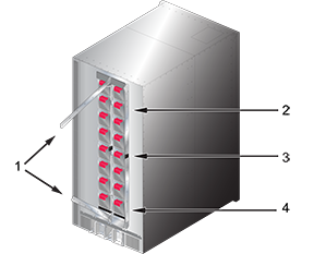
DCS-7304 Fabric and Fan-only Module (left) depicts a DCS-7304 chassis with installed fabric modules (slots 1 and 2) and fan-only modules (slots 3 and 4). Lock levers are shown in the open (slot 3) and closed (slot 4) position DCS-7304 Fan-only Module (right) displays the position of the lock lever release screw (below the extended handles).
The fan direction indicator is located below the top handle. Refer to Site Selection for airflow configuration requirements.
- Slots 1 and 2 contain fabric modules.
- Slots 3 and 4 contain fan-only modules.
Figure 5. DCS-7304 Fabric and Fan-only Module (left); DCS-7304 Fan-only Module (right)
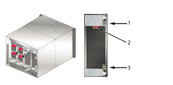
1 Lock lever release screw 2 Fan airflow direction (color indicates airflow direction) 3 Lock lever release screw
Removing Fan-only Modules
This procedure describes the proper method for removing fan-only modules from the switch:
Inserting Fan-only Modules
- Grasping the module by its frame, place the chassis railing corresponding to the slot where it is to be placed. The lock levers should be in the closed position.
- Slide the module into the chassis until it is within three to four inches of being fully inserted.
- Extend the lock levers towards the top and bottom of the chassis.
- Continue inserting the module into the chassis.
- Return the lock levers to the closed position, securing the module to the chassis.
- Secure each lock lever handle to the module by inserting the release screw into the module body and rotating clockwise.