Status Indicators
This section discusses the several status indicators, their location, and the meaning of their display status.
Supervisor Module
While the front panel of each switch can house two supervisors, switch operations require only one. Supervisors display switch component status and contain Ethernet management and console ports.
Fabric and Fan-only Module Description displays the supervisor location on each switch.
The supervisor provides one serial console port, two Ethernet management ports, two USB ports, and one clock input port. Supervisor activity is reported by LEDs in the lower left corner. Four LEDs located right of these LEDs report status of other switch components. Figure 1 - Supervisor Module (DCS-7300(-D)-SUP) displays the Supervisor Module.
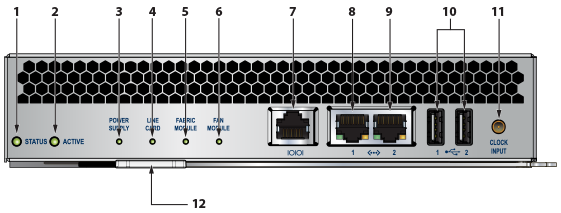
| 1 | Status LED | 5 | Fabric module status LED | 9 | Ethernet management port |
| 2 | Active LED | 6 | Fan module status LED | 10 | USB ports |
| 3 | Power supply status LED | 7 | Console serial port | 11 | Clock input port |
| 4 | Line card status LED | 8 | Ethernet management port | 12 | Release lever |
Supervisor Activity Status LEDs
Table 1 - Supervisor Activity LED States interprets the states of the Status and Active LEDs.
| LED Name | LED State | Supervisor State |
|---|---|---|
| Status | Off | Module failed or is improperly inserted. |
| Green | Supervisor operating normally. | |
| Red | Module failed. | |
| Active | Off | Supervisor is not active. |
| Green | Supervisor is active and controlling the switch. |
Component Activity Status LEDs
LEDs located below the vents and left of the input ports display summary indicators for power supplies, fabric modules, fan modules, and line cards. Table 2 - Component Activity LED States interprets the states of these indicators. When error conditions are indicated, refer to LEDs on the specified modules to determine the condition’s source.
| LED Name | LED State | Module State |
|---|---|---|
| Power Supply Line Card Fabric Module | Off | No modules are present or powered. |
| Green | All powered modules are operating normally. | |
| Red | At least one module has failed. | |
| Fan Modules | Off | Module not inserted. |
| Amber | At least one fan is missing or has failed. | |
| Green | All modules are operating normally. | |
| Red | There are insufficient functional fans installed in the switch. |
Linecard Module Indicators
Each linecard module provides one status LED plus LEDs for each port on the card.
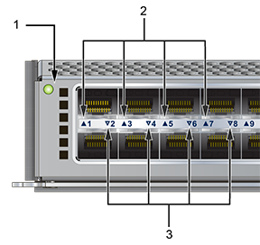
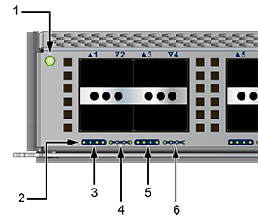
The figures in Linecards indicate the location of the LEDs on each linecard. Figure A-2-left displays the status LED and Port LEDs on the left side of the DCS-7300X-64S-LC linecard. Figure A-2-right displays the status LED and Port LEDs on the left side of the DCS-7300X-32Q-LC linecard.
| 1 | Status LED | 2 | Upper port status LED | 3 | Lower port status LED |
| 1 | Status LED | 2 | 10G/40G QSFP Port LEDs | 3 | QSFP 1 |
| 4 | QSFP 2 | 5 | QSFP 3 | 6 | QSFP 4 |
The Linecard Status LED is in the top left corner of the DCS-7300X Linecard. Table 3 - Linecard Status LED States interprets the states of the Status LED.
| LED State | Status |
|---|---|
| Off | Linecard not inserted. |
| Green | Linecard is operating normally. |
| Yellow | Linecard administratively shut down. |
| Red | Module has failed. |
The linecard provides LEDs for each port module socket:
- Figure 2 - Linecard Status LEDs (DCS-7300X-LC) display SFP module LEDs. Each LED corresponds to a module.
- Figure 3 - Linecard Status LEDs (DCS-7300X-32Q-LC) display QSFP module LEDs. A set of four LEDs correspond to each module. The first LED in the set reports status when the module is programmed as a 40G port. When the module is programmed as four 10G ports, each port is assigned to an LED within the set.
Table 4 - Linecard Port LED States interprets port LED states.
| LED State | Status |
|---|---|
| Off | The port link is down. |
| Green | The port link is up. |
| Yellow | The port is disabled in the software. |
Fan and Fabric Status Indicators
You can access the fan and fabric modules from the rear panel. Fabric modules are inserted into the switch, and fan modules are inserted into the fabric modules.
Each switch contains four fabric modules; the fan module capacity varies by switch model, as displayed in Table 5 - Fan Module Capacity.
| Switch Model | Fabric Capacity | Switch Capacity |
|---|---|---|
| DCS-7304 | 2 fan modules | 8 fan modules |
| DCS-7308 | 4 fan modules | 16 fan modules |
| DCS-7316 | 8 fan modules | 32 fan modules |
The Rear Panels display the rear panel of all switches this guide covers. The Figure 4 - Fan Status and Fabric Status LEDs display a DCS-7304-FM fabric module and the fan modules that it contains.
The fan and fabric module indicators are displayed in the Figure 4 - Fan Status and Fabric Status LEDs. The fan handle indicates the fan direction. All fan modules must have the same color handle.
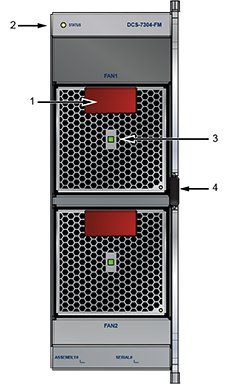
| 1 | Handle (color indicates airflow orientation) | 3 | Fan module installation indicator |
| 2 | Fabric status LED | 4 | Fan module status LED |
The fan module installation indicator is green when the fan module is properly installed or red when the module is not fully installed. The Table 6 - Fan and Fabric Status LED States table interprets the states of the Fan and Fabric Status LEDs.
| LED State | Status |
|---|---|
| Off | The module is inserted but not receiving power – it may not be properly seated. |
| Green | The module is operating normally. |
| Red | The module has failed. |
Power Supply Status Indicators
Power Supply LEDs are on power supply modules. The front panel contains power supply modules for all switches; the DCS-7316 rear panel may also contain power supply modules.
Front Panels and Rear Panels display the position of these LEDs on each switch.
The Figure 5 - Power Supply displays a power supply module.
- All rear panel modules (fan and power supply modules) have the same color handles.
- All front panels (power supply modules) have the same color handles.
-
Rear panel modules and front panel modules have different color handles.
Figure 5. Power Supply
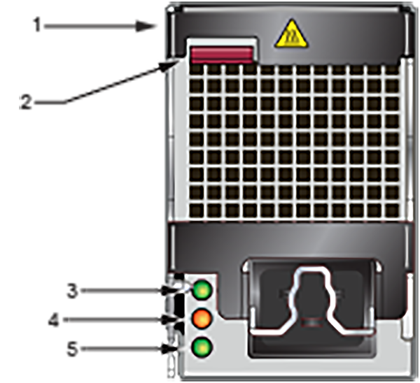
1 Release 3 DC OK LED 5 AC OK LED 2 Ejector (color indicates airflow orientation) 4 Fault LED
The Table 7 - Power Supply Status interprets the states of the Power Supply Status LED.
| AC OK LED | Fault LED | DC OK LED | Status |
|---|---|---|---|
| Green | Off | Green | Power Supply module operating normally. |
| Green | Off | Off | AC is present, Main output is off. |
| Off | Off | Off | No AC power to the module. |
| Green | Amber Blinking | Off | Module has faulted. |