Arista Supported Hardware
This chapter describes the hardware available from Arista to use with the current release of DANZ Monitoring Fabric.
Arista 7050CX3-32C/32S Specifications
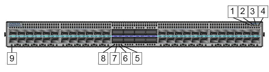
This section describes the LEDs for monitoring environmental and switch port status on the Arista 7050CX3-32C/32S switches.
Switch LEDs for Monitoring Port and Environmental Status
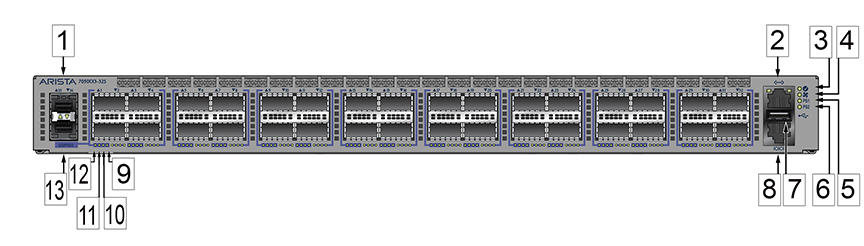
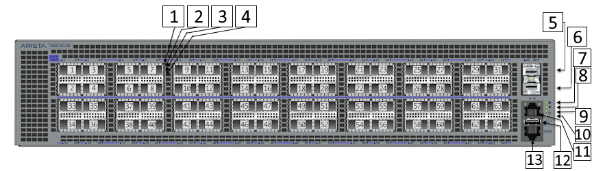
| 1 | Port 33 1/10GbE | 8 | Console port (default baud rate 9600) |
| 2 | Management port | 9 | Port X:4 Breakout 10/25GbE Link/Activity LED |
| 3 | System status/locator LED | 10 | Port X:3 Breakout 10/25GbE Link/Activity LED |
| 4 | Fan status LED | 11 | Port X:2 Breakout 10/25GbE Link/Activity LED |
| 5 | Power supply 1 status LED | 12 | 40/100GbE or Port X:1 Breakout 10/25GbE Link/Activity LED |
| 6 | Power supply 2 status LED | 13 | Port 34 1/10GbE (Not supported) |
| 7 | USB port |
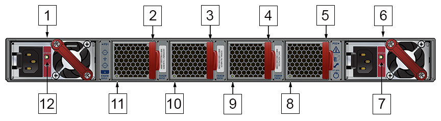
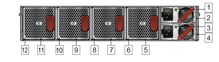
| 1 | PS1 module | 7 | PS2 status LED |
| 2 | Fan1 module | 8 | Fan4 status LED |
| 3 | Fan2 module | 9 | Fan3 status LED |
| 4 | Fan3 module | 10 | Fan2 status LED |
| 5 | Fan4 module | 11 | Fan1 status LED |
| 6 | PS2 module | 12 | PS1 status LED |
Port and Environmental LEDs
| LED | Description |
|---|---|
| System status | Green: Normal operation |
| Green blinking: The system is powering up. | |
| Amber: Two or more fans (any combination of fan modules or PSU fans) are disconnected, malfunctioning, or incompatible. | |
| Blue/Blinking Blue: The locater function is active. | |
| PSU[1:2] status | Green: Normal operation |
| Red: One of the power supplies has failed or is missing. | |
| Off: No power | |
| Fan status | Green: Fan modules are powered and running at the expected rpm. |
| Amber blinking: One or more fan trays failed. | |
| Status LED on power supply | Green: Input power present - Normal operation |
| Amber: Input power present - Power supply fault. | |
| Off: No input power supply installed in chassis. | |
| Status LED on fan tray | Green: The fan is operating normally. This LED state is exclusive to its fan module and independent of the states of its neighboring fans and power supplies. |
| Red: The fan has failed. | |
| Off: Detects no fan module. If the fan is there, it may not be seated properly. |
| Port | LED | Description |
|---|---|---|
| 1GbE SFP
10GbE SFP+ |
Link status | Green: Establishes a valid 1/10GbE network link |
| Amber: The link is disabled. | ||
| Off: Link is down. | ||
| 40GbE QSFP+
100GbE QSFP28 |
Link status | Green: Establishes a valid 40/100GbE network link |
| Amber: The link is disabled. | ||
| Off: Link is down. | ||
| 4X10G QSFP+ breakout
4X25G QSFP28 breakout |
Link status | Green: Establishes a valid 10/25GbE network link |
| Amber: The link is disabled. | ||
| Off: Link is down. | ||
| Management port | Link /Activity | Green: Establishes a valid network link. |
| Green blinking: Network activity in progress. | ||
| Off: Link is down. | ||
| Speed | Green: Establishes a valid 10/100/1000Mb/s network link. | |
| Off: Link is down. |
Arista 7050SX3-48C8/48C8C Specifications
This section describes the LEDs for monitoring environmental and switch port status on the Arista 7050SX3-48C8/48C8C switches.
Switch LEDs for Monitoring Port and Environmental Status
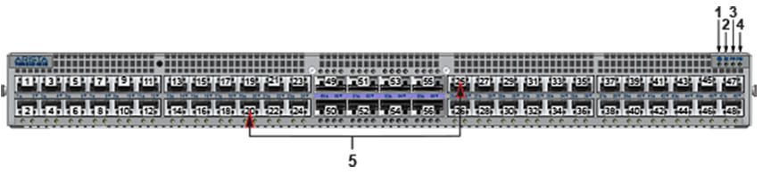
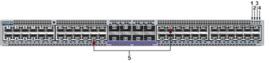
| 1 | System status LED | 4 | Power supply 2 status LED |
| 2 | Fan status LED | 5 | Port numbers |
| 3 | Power supply 1 status LED |
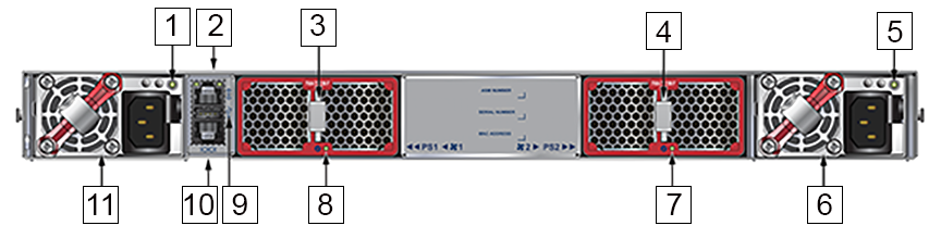
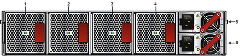
| 1 | PS1 status LED | 7 | Fan2 status LED |
| 2 | Management port | 8 | Fan1 status LED |
| 3 | Fan1 module | 9 | USB port |
| 4 | Fan2 module | 10 | Console port (default baud rate 9600) |
| 5 | PS2 status LED | 11 | PS1 module |
| 6 | PS2 module |
Port and Environmental LEDs
| LED | Description |
|---|---|
| System status | Green: Normal operation |
| Green blinking: The system is powering up. | |
| Amber: Two or more fans (any combination of fan modules or PSU fans) are disconnected, malfunctioning, or incompatible. | |
| Blue/Blinking Blue: The locater function is active. | |
| PSU[1:2] status | Green: Normal operation |
| Red: One of the power supplies has failed or is missing. | |
| Off: No power | |
| Fan status | Green: Fan modules are powered and running at the expected rpm. |
| Amber blinking: One or more fan trays failed. | |
| Status LED on power supply | Green: Input power present - Normal operation |
| Amber: Input power present - Power supply fault. | |
| Off: No input power supply installed in chassis. | |
| Status LED on fan tray | Green: The fan is operating normally. This LED state is exclusive to its fan module and independent of the states of its neighboring fans and power supplies. |
| Red: The fan has failed. | |
| Off: Detects no fan module. If the fan is there, it may not be seated properly. |
| Port | LED | Description |
|---|---|---|
| 1GbE SFP
10GbE SFP+ |
Link status | Green: Establishes a valid 1/10GbE network link |
| Amber: The link is disabled. | ||
| Off: Link is down. | ||
| 40GbE QSFP+
100GbE QSFP28 |
Link status | Green: Establishes a valid 40/100GbE network link |
| Amber: The link is disabled. | ||
| Off: Link is down. | ||
| 4X10G QSFP+ breakout
4X25G QSFP28 breakout |
Link status | Green: Establishes a valid 10/25GbE network link |
| Amber: The link is disabled. | ||
| Off: Link is down. | ||
| Management port | Link /Activity | Green: Establishes a valid network link. |
| Green blinking: Network activity in progress. | ||
| Off: Link is down. | ||
| Speed | Green: Establishes a valid 10/100/1000Mb/s network link. | |
| Off: Link is down. |
Arista 7050SX3-48YC8/48YC8C Specifications
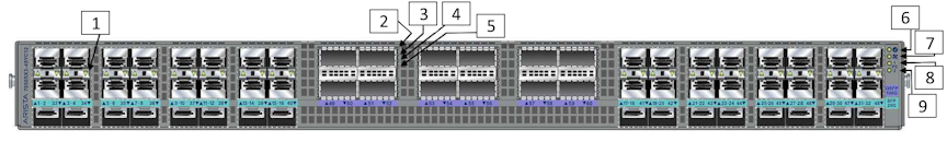
This section describes the LEDs for monitoring environmental and switch port status on the Arista 7050SX3-48YC8/48YC8C switches.
Switch LEDs for Monitoring Port and Environmental Status
| 1 | System status/locator LED | 6 | Port X:3 Breakout 10/25GbE Link/Activity LED |
| 2 | Fan status LED | 7 | Port X:2 Breakout 10/25GbE Link/Activity LED |
| 3 | Power supply 1 status LED | 8 | 40/100GbE or Port X:1 Breakout 10/25GbE Link/Activity LED |
| 4 | Power supply 2 status LED | 9 | 1/10/25GbE Link LED |
| 5 | Port X:4 Breakout 10/25GbE Link/Activity LED |
| 1 | PS1 status LED | 7 | Fan2 status LED |
| 2 | Management port | 8 | Fan1 status LED |
| 3 | Fan1 module | 9 | USB port |
| 4 | Fan2 module | 10 | Console port (default baud rate 9600) |
| 5 | PS2 status LED | 11 | PS1 module |
| 6 | PS2 module |
Port and Environmental LEDs
| LED | Description |
|---|---|
| System status | Green: Normal operation |
| Green blinking: The system is powering up. | |
| Amber: Two or more fans (any combination of fan modules or PSU fans) are disconnected, malfunctioning, or incompatible. | |
| Blue/Blinking Blue: The locater function is active. | |
| PSU[1:2] status | Green: Normal operation |
| Red: One of the power supplies has failed or is missing. | |
| Off: No power | |
| Fan status | Green: Fan modules are powered and running at the expected rpm. |
| Amber blinking: One or more fan trays failed. | |
| Status LED on power supply | Green: Input power present - Normal operation |
| Amber: Input power present - Power supply fault. | |
| Off: No input power supply installed in chassis. | |
| Status LED on fan tray | Green: The fan is operating normally. This LED state is exclusive to its fan module and independent of the states of its neighboring fans and power supplies. |
| Red: The fan has failed. | |
| Off: Detects no fan module. If the fan is there, it may not be seated properly. |
| Port | LED | Description |
|---|---|---|
| 1GbE SFP
10GbE SFP+ 25GbE SFP28 |
Link status | Green: Establishes a valid 1/10/25GbE network link |
| Amber: The link is disabled. | ||
| Off: Link is down. | ||
| 40GbE QSFP+
100GbE QSFP28 |
Link status | Green: Establishes a valid 40/100GbE network link |
| Amber: The link is disabled. | ||
| Off: Link is down. | ||
| 4X10G QSFP+ breakout
4X25G QSFP28 breakout |
Link status | Green: Establishes a valid 10/25GbE network link |
| Amber: The link is disabled. | ||
| Off: Link is down. | ||
| Management port | Link /Activity | Green: Establishes a valid network link. |
| Green blinking: Network activity in progress. | ||
| Off: Link is down. | ||
| Speed | Green: Establishes a valid 10/100/1000Mb/s network link. | |
| Off: Link is down. |
Arista 7050SX3-48YC12 Specifications
This section describes the LEDs for monitoring environmental and switch port status on the Arista 7050SX3-48YC12 switch.
- Interface 1-4
- Interface 5-8
- Interface 9-12
- Interface 13-16
- Interface 17-20
- Interface 21-24
- Interface 25-28
- Interface 29-32
- Interface 33-36
- Interface 37-40
- Interface 41-44
- Interface 45-48
The speed of the first optical cable inserted into a group is automatically detected, which sets the speed for all the interfaces in the group.
For example, if the first group (interface 1-4) is empty and when inserting a 25G cable into Interface 2, interfaces 1 to 4 are all automatically set to 25G, and no other speed is allowed in the group.
If you later insert a 10G cable into any interface in the group, the system does not bring up the 10G interface. You can bring up the 10G interface only if no cable of a different speed is present in any interface in the group.
Only the first interface connected is enabled when cables of different speeds are present in interfaces within a single group. However, when the switch restarts later with the cables inserted, the first interface in the group numerically is enabled. For example, with a 25G cable in Interface 2 and a 10G cable in Interface 1, interface 1 is enabled at 10G when the switch restarts and all the interfaces are at 10.
Switch LEDs for Monitoring Port and Environmental Status
| 1 | 1/10/25GbE Link LED | 6 | System status/locator LED |
| 2 | 40/100GbE or Port X:1 Breakout 10/25GbE Link/Activity LED | 7 | Fan status LED |
| 3 | Port X:2 Breakout 10/25GbE Link/Activity LED | 8 | Power supply 1 status LED |
| 4 | Port X:3 Breakout 10/25GbE Link/Activity LED | 9 | Power supply 2 status LED |
| 5 | Port X:4 Breakout 10/25GbE Link/Activity LED |
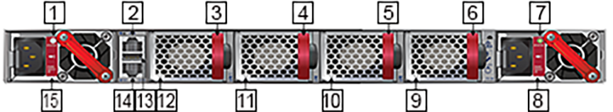
| 1 | PS1 status LED | 9 | Fan4 status LED |
| 2 | Management port | 10 | Fan3 status LED |
| 3 | Fan1 module | 11 | Fan2 status LED |
| 4 | Fan2 module | 12 | Fan1 status LED |
| 5 | Fan3 module | 13 | USB port |
| 6 | Fan4 module | 14 | Console port (default baud rate 9600) |
| 7 | PS2 status LED | 15 | PS1 module |
| 8 | PS2 module |
Port and Environmental LEDs
| LED | Description |
|---|---|
| System status | Green: Normal operation |
| Green blinking: The system is powering up. | |
| Amber: Two or more fans (any combination of fan modules or PSU fans) are disconnected, malfunctioning, or incompatible. | |
| Blue/Blinking Blue: The locater function is active. | |
| PSU[1:2] status | Green: Normal operation |
| Red: One of the power supplies has failed or is missing. | |
| Off: No power | |
| Fan status | Green: Fan modules are powered and running at the expected rpm. |
| Amber blinking: One or more fan trays failed. | |
| Status LED on power supply | Green: Input power present - Normal operation |
| Amber: Input power present - Power supply fault. | |
| Off: No input power supply installed in chassis. | |
| Status LED on fan tray | Green: The fan is operating normally. This LED state is exclusive to its fan module and independent of the states of its neighboring fans and power supplies. |
| Red: The fan has failed. | |
| Off: Detects no fan module. If the fan is there, it may not be seated properly. |
| Port | LED | Description |
|---|---|---|
| 1GbE SFP
10GbE SFP+ 25GbE SFP28 |
Link status | Green: Establishes a valid 1/10/25GbE network link |
| Amber: The link is disabled. | ||
| Off: Link is down. | ||
| 40GbE QSFP+
100GbE QSFP28 |
Link status | Green: Establishes a valid 40/100GbE network link |
| Amber: The link is disabled. | ||
| Off: Link is down. | ||
| 4X10G QSFP+ breakout
4X25G QSFP28 breakout |
Link status | Green: Establishes a valid 10/25GbE network link |
| Amber: The link is disabled. | ||
| Off: Link is down. | ||
| Management port | Link /Activity | Green: Establishes a valid network link. |
| Green blinking: Network activity in progress. | ||
| Off: Link is down. | ||
| Speed | Green: Establishes a valid 10/100/1000Mb/s network link. | |
| Off: Link is down. |
Arista 7050SX3-96YC8 Specifications
This section describes the LEDs for monitoring environmental and switch port status on the Arista 7050SX3-96YC8 switch.
- Interface 1-4
- Interface 5-8
- Interface 9-12
- Interface 13-16
- Interface 17-20
- Interface 21-24
- Interface 25-28
- Interface 29-32
- Interface 33-36
- Interface 37-40
- Interface 41-44
- Interface 45-48
- Interface 49-52
- Interface 53-56
- Interface 57-60
- Interface 61-64
- Interface 65-68
- Interface 69-72
- Interface 73-76
- Interface 77-80
- Interface 81-84
- Interface 85-88
- Interface 89-92
- Interface 93-96
The speed of the first optical cable inserted into a group is automatically detected, which sets the speed for all the interfaces in the group.
For example, if the first group (interface 1-4) is empty and when inserting a 25G cable into Interface 2, interfaces 1 to 4 are all automatically set to 25G, and no other speed is allowed in the group.
If you later insert a 10G cable into any interface in the group, the system does not bring up the 10G interface. You can bring up the 10G interface only if no cable of a different speed is present in any interface in the group.
Only the first interface connected is enabled when cables of different speeds are present in interfaces within a single group. However, when the switch restarts later with the cables inserted, the first interface in the group numerically is enabled. For example, with a 25G cable in Interface 2 and a 10G cable in Interface 1, interface 1 is enabled at 10G when the switch restarts and all the interfaces are at 10.
Switch LEDs for Monitoring Port and Environmental Status
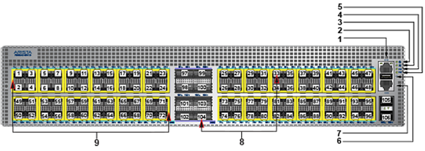
| 1 | 1/10/25GbE Link LED | 6 | System status/locator LED |
| 2 | 40/100GbE or Port X:1 Breakout 10/25GbE Link/Activity LED | 7 | Fan status LED |
| 3 | Port X:2 Breakout 10/25GbE Link/Activity LED | 8 | Power supply 1 status LED |
| 4 | Port X:3 Breakout 10/25GbE Link/Activity LED | 9 | Power supply 2 status LED |
| 5 | Port X:4 Breakout 10/25GbE Link/Activity LED |
| 1 | Fan1 module | 4 | Fan4 module |
| 2 | Fan2 module | 5 | Power supply module 1 |
| 3 | Fan3 module | 6 | Power supply module 2 |
Port and Environmental LEDs
| LED | Description |
|---|---|
| System status | Green: Normal operation |
| Green blinking: The system is powering up. | |
| Amber: Two or more fans (any combination of fan modules or PSU fans) are disconnected, malfunctioning, or incompatible. | |
| Blue/Blinking Blue: The locater function is active. | |
| PSU[1:2] status | Green: Normal operation |
| Red: One of the power supplies has failed or is missing. | |
| Off: No power | |
| Fan status | Green: Fan modules are powered and running at the expected rpm. |
| Amber blinking: One or more fan trays failed. | |
| Status LED on power supply | Green: Input power present - Normal operation |
| Amber: Input power present - Power supply fault. | |
| Off: No input power supply installed in chassis. | |
| Status LED on fan tray | Green: The fan is operating normally. This LED state is exclusive to its fan module and independent of the states of its neighboring fans and power supplies. |
| Red: The fan has failed. | |
| Off: Detects no fan module. If the fan is there, it may not be seated properly. |
| Port | LED | Description |
|---|---|---|
| 1GbE SFP
10GbE SFP+ 25GbE SFP28 |
Link status | Green: Establishes a valid 1/10/25GbE network link |
| Amber: The link is disabled. | ||
| Off: Link is down. | ||
| 40GbE QSFP+
100GbE QSFP28 |
Link status | Green: Establishes a valid 40/100GbE network link |
| Amber: The link is disabled. | ||
| Off: Link is down. | ||
| 4X10G QSFP+ breakout
4X25G QSFP28 breakout |
Link status | Green: Establishes a valid 10/25GbE network link |
| Amber: The link is disabled. | ||
| Off: Link is down. | ||
| Management port | Link /Activity | Green: Establishes a valid network link. |
| Green blinking: Network activity in progress. | ||
| Off: Link is down. | ||
| Speed | Green: Establishes a valid 10/100/1000Mb/s network link. | |
| Off: Link is down. |
Arista 7050TX3-48C8 Specifications
This section describes the LEDs for monitoring environmental and switch port status on the Arista 7050TX3-48C8 switch.
Switch LEDs for Monitoring Port and Environmental Status
| 1 | System status LED | 4 | Power supply 2 status LED |
| 2 | Fan status LED | 5 | Port numbers |
| 3 | Power supply 1 status LED |
| 1 | PS1 status LED | 7 | Fan2 status LED |
| 2 | Management port | 8 | Fan1 status LED |
| 3 | Fan1 module | 9 | USB port |
| 4 | Fan2 module | 10 | Console port (default baud rate 9600) |
| 5 | PS2 status LED | 11 | PS1 module |
| 6 | PS2 module |
Port and Environmental LEDs
| LED | Description |
|---|---|
| System status | Green: Normal operation |
| Green blinking: The system is powering up. | |
| Amber: Two or more fans (any combination of fan modules or PSU fans) are disconnected, malfunctioning, or incompatible. | |
| Blue/Blinking Blue: The locater function is active. | |
| PSU[1:2] status | Green: Normal operation |
| Red: One of the power supplies has failed or is missing. | |
| Off: No power | |
| Fan status | Green: Fan modules are powered and running at the expected rpm. |
| Amber blinking: One or more fan trays failed. | |
| Status LED on power supply | Green: Input power present - Normal operation |
| Amber: Input power present - Power supply fault. | |
| Off: No input power supply installed in chassis. | |
| Status LED on fan tray | Green: The fan is operating normally. This LED state is exclusive to its fan module and independent of the states of its neighboring fans and power supplies. |
| Red: The fan has failed. | |
| Off: Detects no fan module. If the fan is there, it may not be seated properly. |
| Port | LED | Description |
|---|---|---|
| 1GBase-T
10GBase-T |
Link status | Green: Establishes a valid 1/10GbE network link |
| Amber: The link is disabled. | ||
| Off: Link is down. | ||
| 40GbE QSFP+
100GbE QSFP28 |
Link status | Green: Establishes a valid 40/100GbE network link |
| Amber: The link is disabled. | ||
| Off: Link is down. | ||
| 4X10G QSFP+ breakout
4X25G QSFP28 breakout |
Link status | Green: Establishes a valid 10/25GbE network link |
| Amber: The link is disabled. | ||
| Off: Link is down. | ||
| Management port | Link /Activity | Green: Establishes a valid network link. |
| Green blinking: Network activity in progress. | ||
| Off: Link is down. | ||
| Speed | Green: Establishes a valid 10/100/1000Mb/s network link. | |
| Off: Link is down. |
Arista 7260CX3-64 Specifications
This section describes the LEDs for monitoring environmental and switch port status on the Arista 7260CX3-64 switch.
Switch LEDs for Monitoring Port and Environmental Status
| 1 | 40/100GbE or Port X:1 Breakout 10/25GbE Link/Activity LED | 8 | Fan status LED |
| 2 | Port X:2 Breakout 10/25GbE Link/Activity LED | 9 | Power supply 1 status LED |
| 3 | Port X:3 Breakout 10/25GbE Link/Activity LED | 10 | Power supply 2 status LED |
| 4 | Port X:4 Breakout 10/25GbE Link/Activity LED | 11 | Management port |
| 5 | Port 65 1/10GbE | 12 | USB port |
| 6 | Port 66 1/10GbE | 13 | Console port (default baud rate 9600) |
| 7 | System status/locator LED |
| 1 | PS1 status LED | 7 | Fan3 module |
| 2 | PS1 module | 8 | Fan3 status LED |
| 3 | PS2 status LED | 9 | Fan2 module |
| 4 | PS2 module | 10 | Fan2 status LED |
| 5 | Fan4 module | 11 | Fan1 module |
| 6 | Fan4 status LED | 12 | Fan1 status LED |
Port and Environmental LEDs
| LED | Description |
|---|---|
| System status | Green: Normal operation |
| Green blinking: The system is powering up. | |
| Amber: Two or more fans (any combination of fan modules or PSU fans) are disconnected, malfunctioning, or incompatible. | |
| Blue/Blinking Blue: The locater function is active. | |
| PSU[1:2] status | Green: Normal operation |
| Red: One of the power supplies has failed or is missing. | |
| Off: No power | |
| Fan status | Green: Fan modules are powered and running at the expected rpm. |
| Amber blinking: One or more fan trays failed. | |
| Status LED on power supply | Green: Input power present - Normal operation |
| Amber: Input power present - Power supply fault. | |
| Off: No input power supply installed in chassis. | |
| Status LED on fan tray | Green: The fan is operating normally. This LED state is exclusive to its fan module and independent of the states of its neighboring fans and power supplies. |
| Red: The fan has failed. | |
| Off: Detects no fan module. If the fan is there, it may not be seated properly. |
| Port | LED | Description |
|---|---|---|
| 1GBase-T
10GBase-T |
Link status | Green: Establishes a valid 1/10GbE network link |
| Amber: The link is disabled. | ||
| Off: Link is down. | ||
| 40GbE QSFP+
100GbE QSFP28 |
Link status | Green: Establishes a valid 40/100GbE network link |
| Amber: The link is disabled. | ||
| Off: Link is down. | ||
| 4X10G QSFP+ breakout
4X25G QSFP28 breakout |
Link status | Green: Establishes a valid 10/25GbE network link |
| Amber: The link is disabled. | ||
| Off: Link is down. | ||
| Management port | Link /Activity | Green: Establishes a valid network link. |
| Green blinking: Network activity in progress. | ||
| Off: Link is down. | ||
| Speed | Green: Establishes a valid 10/100/1000Mb/s network link. | |
| Off: Link is down. |
Arista 7260CX3-64E Specifications
This section describes the LEDs for monitoring environmental and switch port status on the Arista 7260CX3-64E switch.
Switch LEDs for Monitoring Port and Environmental Status
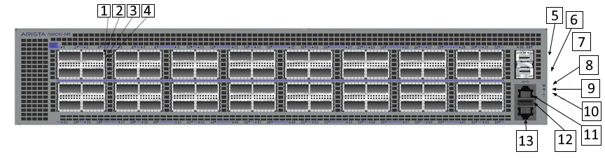
| 1 | 40/100GbE or Port X:1 Breakout 10/25GbE Link/Activity LED | 8 | Fan status LED |
| 2 | Port X:2 Breakout 10/25GbE Link/Activity LED | 9 | Power supply 1 status LED |
| 3 | Port X:3 Breakout 10/25GbE Link/Activity LED | 10 | Power supply 2 status LED |
| 4 | Port X:4 Breakout 10/25GbE Link/Activity LED | 11 | Management port |
| 5 | Port 65 1/10GbE | 12 | USB port |
| 6 | Port 66 1/10GbE | 13 | Console port (default baud rate 9600) |
| 7 | System status/locator LED |
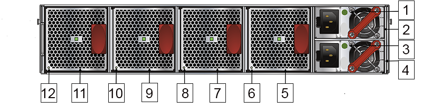
| 1 | PS2 module | 7 | Fan3 module |
| 2 | PS2 status LED | 8 | Fan3 status LED |
| 3 | PS1 module | 9 | Fan2 module |
| 4 | PS1 status LED | 10 | Fan2 status LED |
| 5 | Fan4 module | 11 | Fan1 module |
| 6 | Fan4 status LED | 12 | Fan1 status LED |
Port and Environmental LEDs
| LED | Description |
|---|---|
| System status | Green: Normal operation |
| Green blinking: The system is powering up. | |
| Amber: Two or more fans (any combination of fan modules or PSU fans) are disconnected, malfunctioning, or incompatible. | |
| Blue/Blinking Blue: The locater function is active. | |
| PSU[1:2] status | Green: Normal operation |
| Red: One of the power supplies has failed or is missing. | |
| Off: No power | |
| Fan status | Green: Fan modules are powered and running at the expected rpm. |
| Amber blinking: One or more fan trays failed. | |
| Status LED on power supply | Green: Input power present - Normal operation |
| Amber: Input power present - Power supply fault. | |
| Off: No input power supply installed in chassis. | |
| Status LED on fan tray | Green: The fan is operating normally. This LED state is exclusive to its fan module and independent of the states of its neighboring fans and power supplies. |
| Red: The fan has failed. | |
| Off: Detects no fan module. If the fan is there, it may not be seated properly. |
| Port | LED | Description |
|---|---|---|
| 1GBase-T
10GBase-T |
Link status | Green: Establishes a valid 1/10GbE network link |
| Amber: The link is disabled. | ||
| Off: Link is down. | ||
| 40GbE QSFP+
100GbE QSFP28 |
Link status | Green: Establishes a valid 40/100GbE network link |
| Amber: The link is disabled. | ||
| Off: Link is down. | ||
| 4X10G QSFP+ breakout
4X25G QSFP28 breakout |
Link status | Green: Establishes a valid 10/25GbE network link |
| Amber: The link is disabled. | ||
| Off: Link is down. | ||
| Management port | Link /Activity | Green: Establishes a valid network link. |
| Green blinking: Network activity in progress. | ||
| Off: Link is down. | ||
| Speed | Green: Establishes a valid 10/100/1000Mb/s network link. | |
| Off: Link is down. |
Arista 7050X4-Series Specifications
The Arista 7050X4 are a member of the Arista 7050X series and a key components of the Arista portfolio of data center switches. Given that the 7050X4 series switch runs EOS, for a description of LEDs provided for monitoring environmental and switch port status on the switch, refer to the Quick Start Guide and other related info for the 7050X4 series of switches as follows:
Arista 7280-Series Specifications
The Arista 7280 Series of fixed and modular switches runs EOS. For a description of LEDs provided for monitoring environmental and switch port status on the switch, refer to the Quick Start Guide and other related info for the 7280 series of switches as follows:
Arista 7289 and 7800-Series Specifications
The 7289 and 7800 series modular switches run on EOS. For a description of LEDs provided for monitoring environmental and switch port status on the switch, refer to the Quick Start Guide and other related info for the 7289 and 7800 series of switches as follows:
https://www.arista.com/en/qsg-7368x-series
https://www.arista.com/en/qsg-7800-series