Front Panel Features and Indicators
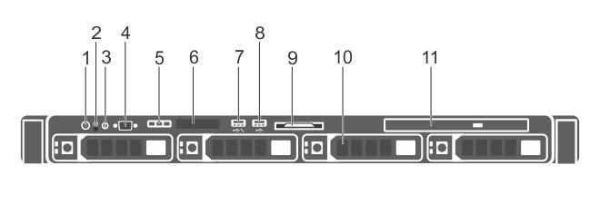
This appendix displays the front panel of the CloudVision appliance.
| Indicator, Button, or Connector | Description | |
|---|---|---|
| 1 | Power-on indicator, power button |
The power-on indicator lights when the system power is on. The power button controls the power supply output to the system. Note: On ACPI-compliant operating systems, turning off the system using the power button causes the system to perform a graceful shutdown before power to the system is turned off.
|
| 2 | NMI button |
Used to troubleshoot software and device driver errors when running certain operating systems. This button can be pressed using the end of a paper clip. Note: Use this button only if directed to do so by qualified support personnel.
|
| 3 | System identification button |
The identification buttons on the front and back panels can be used to locate a particular system within a rack. When one of these buttons is pressed, the system status indicator on the back flashes until one of the buttons is pressed again. Press to toggle the system ID on and off. If the system stops responding during POST, press and hold the system ID button for more than five seconds to enter BIOS progress mode. To reset the iDRAC (if not disabled in F2 iDRAC setup) press and hold the button for more than 15 seconds. |
| 4 | Video connector | Allows you to connect a display to the system. |
| 5 | Diagnostic indicators | The diagnostic indicator lights up to display error status. |
| 6 | LCD panel | Displays system ID, status information, and system error messages. |
| 7 |
USB management port/iDRAC managed USB port |
The USB management port can function as a regular USB port or provide access to the iDRAC features. |
| 8 | USB connector |
Allows you to connect USB devices to the system. The port is USB 2.0-compliant. |
| 9 | Information tag |
A slide-out label panel which contains system information such as Service Tag, NIC, MAC address, and so on for your reference. |
| 10 | Hard drives | Up to four 3.5 inch hot-swappable hard drives/SSDs. |
| 11 | Optical drive (optional) | One optional slim SATA DVD-ROM drive or DVD+/-RW drive. |
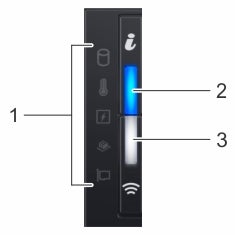
Left Control Panel View
| Item | Indicator, button, or connector | Icon | Description |
|---|---|---|---|
| 1 | Status LED indicators | N/A | Indicate the status of the system. |
| 2 | System health and system ID indicator | Indicates the system health. | |
| 3 | IPMI Quick Sync 2 wireless indicator (optional)
Note: IPMI Quick Sync 2 wireless indicator is available only on certain configurations.
|
Indicates if the IPMI Quick Sync 2 wireless option is activated. The Quick Sync 2 feature allows management of the system using mobile devices. This feature aggregates hardware/firmware inventory and various system level diagnostic/error information that can be used in troubleshooting the system. You can access system inventory, Lifecycle Controller logs or system logs, system health status, and also configure IPMI, BIOS, and networking parameters. You can also launch the virtual Keyboard, Video, and Mouse (KVM) viewer and virtual Kernel-based Virtual Machine (KVM), on a supported mobile device. |
Right Control Panel View
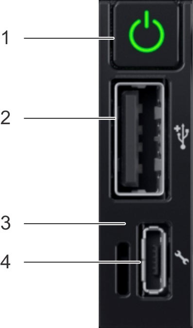
Item 1 is the power button, indicates if the system is turned on or off.
Item 2 is the USB port, enables you to connect USB devices to the system.
Item 3 is the iDRAC Direct LED, indicates that the IPMI Direct port is connected.
Item 4 is the iDRAC Direct port, enables you to access the IPMI direct features.
| Item | Indicator or button | Icon | Description |
|---|---|---|---|
| 1 | Power button | Power ON, power OFF. | |
| 2 | USB port | The USB ports are 4-pin, 2.0-compliant. This port enables you to connect USB devices to the system. | |
| 3 | IPMI Direct LED | N/A | The IPMI Direct LED indicator lights up to indicate that the IPMI Direct port is actively connected to a device. |
| 4 | IPMI Direct port (Micro-AB USB) | The IPMI Direct (Micro-AB USB) port enables you to access the IPMI Direct (Micro-AB) features. |