Install the Access Point
This chapter explains the procedure to install the access point (AP).
Zero-Configuration of the Access Point
Zero-configuration is supported under the following conditions:- The device is in the AP mode with background scanning ON and no SSID configured.
- The DNS entry, wifi-security-server, is configured on all the DNS servers. This entry must point to the IP address of the server. By default, the AP looks for the wifi-security-server DNS entry.
- The AP is on a subnet that is DHCP enabled.
Take a configured AP; that is, ensure that a static IP is assigned to the AP or the settings have been changed for DHCP. Note the MAC address and the IP address of the AP in a safe place before it is installed in a hard-to-reach location. The MAC address of the AP is printed on a label at the bottom of the product.
Mount the Access Point
Table Mount the Access Point
- Plug the network cable (Ethernet cable) into the WAN port (PoE++) located at the back of the AP as shown below. If the network is not PoE enabled, plug the Power Adaptor at the DC Input port, as shown.
Figure 1. Attach cables to AP 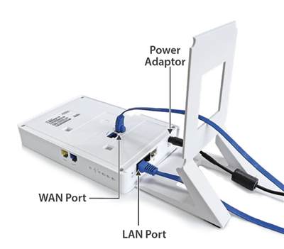
- Flip the stand on the AP as shown, aligning the hooks on the stand to the grooves on the AP. Slide the hooks into the grooves to attach the AP to the stand.
Figure 2. Attach stand to AP 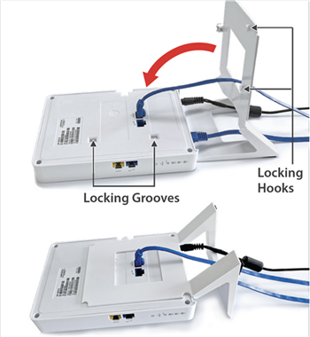
- The spring-loaded pin will automatically lock into the locking hole of the AP. If the pin is not aligned, pull the pin and align it to the locking hole. Note: To remove the AP from the stand, pull the pin and then remove the AP.
Figure 3. Image showing the spring-loaded pin 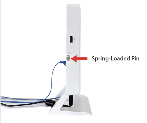
Use LAN 1, LAN 2, and LAN 3 ports at the bottom of the AP to connect to local devices.
Wall Mount the Access Point
For instructions on wall mounting the access point, refer to Wall Mount the Access Point article.
Connect the Access Point to the Network
- Ensure that a DHCP server is available on the network to enable network configuration of the AP.
- Add the DNS entry wifi-security-server on all DNS servers. This entry should point to the IP address of the server.
- Ensure that DHCP is running on the subnet to which the AP will be connected.
- Check the status LEDs on the AP. If all LEDs glow green, then the AP is operational and connected to the server.
- Log on to the server using ssh and run the get sensor list command.
You will see a list of all Arista devices that are recognized by the server. Single Sign-On users can go to the tab in CloudVision Cognitive Unified Edge and check whether the AP is visible under the Access Points tab.
Connect the Access Point Using PoE

Power On the Access Point
As an alternative to PoE, you can insert a compatible power adapter plug into an AC power outlet and the other end into the power input port on the AP.
Using the Access Point with Power Adapter
- Plug the power cable into the DC power receptacle at the rear of the AP.
- Plug the other end of the power cable into an 110V~240V 50/60 Hz AC power source.
- Wait until the LED lights on the AP are lit. Refer to the LED details table.