Data Plane Security
IP NAT
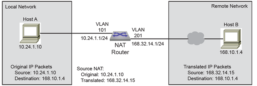
Network Address Translation (NAT) is a router process that modifies the address information of IP packets in transit. NAT is typically used to correlate address spaces between a local network and a remote, often public, network. Static NAT defines a one-to-one map between local and remote IP addresses. Static maps are configured manually through CLI commands. An interface can support multiple NAT commands, but each command must specify a unique local IP address-port location.
NAT is configured on routers with interfaces connecting to the local networks and interfaces connecting to a remote network.
Inside and Outside Addresses
NAT configurations categorize IP addresses into one of two categories: inside or outside. Inside refers to IP addresses used within the organizational network, while outside refers to addresses on an external network outside the organizational network.
Static IP NAT
Static NAT configurations create a one-to-one mapping and translate a particular address to another address. This type of configuration creates a permanent entry in the NAT table as long as the configuration is present, enabling both inside and outside hosts to initiate a connection.
- Source NAT modifies the source address in the IP header of a packet exiting the interface and can optionally change the source port referenced in the TCP/UDP headers.
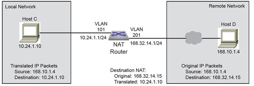
- Destination NAT modifies the destination address in the IP header of a packet entering the interface and can optionally change the destination port referenced in the TCP/UDP headers.
- Twice NAT modifies both the source and destination IP addresses of packets traversing the interface. The process optionally changes L4 port information within TCP/UDP headers. Implement Twice NAT to prevent conflicts when inside network addresses overlap with outside network addresses. When a packet exits the interface, local source and destination addresses are translated to global source and destination addresses. When a packet enters the interface, global source and destination addresses are translated to local source and destination addresses.
Configuring Static NAT
Configuring Source NAT
Enable the NAT of a source address (source NAT) using the ip nat source static command for the configuration mode interface. Applying source NAT to interfaces that connect to local hosts shields the hosts' IP address when sending IP packets to remote destinations.
This command installs hardware translation entries for forward and reverse unicast traffic. When the rule specifies a multicast group, the command does not install the reverse path in hardware. The command may include an access control list to filter packets for translation.
Example
switch(config)# interface vlan 201
switch(config-if-Vl201)# ip nat source static 10.24.1.10 168.32.14.15
switch(config-if-Vl201)#
The ip nat source static command may include an ACL to limit packet translation. Only packets whose source IP address matches the ACL are cleared. ACLs configured for source NAT must specify a source IP address of any. Source port or protocol matching is not permitted. The destination may be an IP subnet. Commands referencing nonexistent ACLs are accepted by the CLI but only installed in hardware once the ACL is created. Modifying a referenced ACL causes the corresponding hardware entries to be replaced by entries that match the new command.
Example
switch(config)# ip access-list ACL1
switch(config-acl-ACL1)# permit ip any 168.10.1.0/24
switch(config-acl-ACL1)# exit
switch(config)# interface vlan 101
switch(config-if-Vl101)# ip nat source static 10.24.1.10 access-list ACL1 168.32.14.15
switch(config-if-Vl101)#
Configuring Destination NAT
Enable the NAT of a destination address (destination NAT) using the ip nat destination static command for the configuration mode interface. Applying destination NAT to interfaces that connect to remote hosts shields the IP address of the recipient host when receiving IP packets from remote destinations.
This command installs hardware translation entries for forward and reverse unicast traffic. When the rule specifies a multicast group, the command does not install the reverse path in hardware. The command may include an access control list to filter packets for translation.
Example
switch(config)# interface vlan 201
switch(config-if-Vl201)# ip nat destination static 168.32.14.15 10.24.1.10
switch(config-if-Vl201)#
The ip nat destination static command may include an ACL to limit packet translation. Only packets whose source IP address matches the ACL are cleared. ACLs configured for destination NAT must specify a destination IP address of any. Destination port or protocol matching is not permitted. The source may be an IP subnet. Commands referencing nonexistent ACLs are accepted by the CLI but not installed in hardware until the ACL is created. Modifying a referenced ACL causes the corresponding hardware entries to be replaced by entries that match the new command.
Example
switch(config)# ip access-list ACL2
switch(config-acl-ACL2)# permit ip 168.10.1.4/32 any
switch(config-acl-ACL2)# exit
switch(config)# interface vlan 201
switch(config-if-Vl201)# ip nat destination static 168.32.14.15 access-list ACL2 10.24.1.10
switch(config-if-Vl201)#
Configuring Twice NAT
Network address translation of both source and destination addresses on the same interface (twice NAT) is enabled by creating one source NAT rule and one destination NAT rule on the same interface and associating them through a NAT group using the ip nat source static and ip nat destination static commands.
The ip nat source static command translates the actual local source address to a source address, which can be used outside the local network to reference the source. The ip nat destination static command translates an internally used destination address to the actual IP address that is the packet's destination.
The source and destination NAT rules must reference the same NAT group, and both should either specify only IP addresses or specify both IP addresses and L4 port information. An error message will be displayed if L4 port information is configured in one rule but not in the other.
Each NAT rule installs hardware translation entries for forward and reverse unicast traffic. When the rule specifies a multicast group, the command does not install the reverse path in hardware. Twice NAT does not support using access control lists to filter packets for translation.
Example
switch(config)# interface ethernet 2
switch(config-if-Et2)# ip nat source static 10.24.1.10 168.32.14.15 group 3
switch(config-if-Et2)# ip nat destination static 10.68.104.3 168.25.10.7 group 3
Static NAT Configuration Considerations
Egress VLAN Filter for Static NAT
When a static source NAT is configured on an interface, the source IP translation happens only for those packets going 'out' of this interface. If a packet is egressing on an interface that does not have NAT configured, then the source IP is not translated.
When static SNAT is configured on two interfaces, the translation specified for one interface can be applied to a packet going out on the other interface.
- In this example, the packets with source IP 20.1.1.1 going out of E1 will still have the source IP translated to 172.1.1.1 even though the rule is configured in E2 and not on E1.
switch(config)# interface ethernet 1 switch(config-if-Et1)# ip nat source static 10.1.1.1 171.1.1.1 switch(config)# interface ethernet 2 switch(config-if-Et2)# ip nat source static 20.1.1.1 172.1.1.1 - To prevent this, use an ACL to filter the traffic that needs NAT on the interfaces.
switch(config)# ip access-list acl1 switch(config-acl-acl1)# permit ip any 171.1.1.0/24 switch(config)# ip access-list acl2 switch(config-acl-acl2)# permit ip any 172.1.1.0/24 switch(config)# interface ethernet 1 switch(config-if-Et1)# ip nat source static 10.1.1.1 access-list acl1 171.1.1.1 switch(config)# interface ethernet 2 switch(config-if-Et2)# ip nat source static 20.1.1.1 access-list acl2 172.1.1.1 -
ACL filtering is not supported when using twice NAT.
Dynamic NAT
Dynamic NAT offers a solution when fewer outside addresses are available than the number of internal hosts requiring external access. The process creates a dynamic entry in the NAT table when a host initiates an outbound connection. This entry establishes a one-to-one mapping between the internal private address and the available outside address. The specific outside address assigned to a host can vary and depends on the addresses available in the pool at the time of the connection request. Dynamic NAT sessions initiate only from inside networks. NAT should be configured on a Layer 3 interface, either a routed port or a Switch Virtual Interface (SVI). Dynamic NAT entries are removed from the translation table if the host doesn't communicate for a specific period. The address returns to the pool for use by another host.

- Many-to-Many NAT
Many-to-Many NAT maps local addresses to a global address selected from a pool of global addresses. After the pool is configured, the first available address from the pool is picked dynamically on receiving the first packet.
- Many-to-One NAT (PAT)
PAT is a form of dynamic NAT where multiple local addresses are mapped to a single global address (many-to-one) using different source ports. This method is also called NAT Overloading, Network Address Port Translation (NAPT), and Masquerade. The global address can be the IP address configured on the outside interface.
Hardware entries that translate packets are created when the CLI command is processed. Entries for forward and reverse traffic are created for unicast traffic. The hardware entry for reverse traffic is not created for multicast traffic.Commands may include ACLs to filter packets that are cleared. Source NAT uses ACLs to filter packets based on the destination IP address, while destination NAT uses ACLs to filter packets based on the source IP address. When using NAT, inside usually refers to a private network, while outside usually refers to a public network.
A switch with NAT configured translates forwarded traffic between inside and outside interfaces and the flow that matches the criteria specified for translation.The same IP address can't be used for the NAT static configuration and in the pool for dynamic NAT configurations. Public IP addresses must be unique. The global addresses used in static translations aren't excluded from dynamic pools containing the same global addresses.
Commands may include ACLs to filter packets that are cleared. Source NAT uses ACLs to filter packets based on destination IP address. Destination NAT uses ACLs to filter packets based on source IP address. When using NAT, inside usually refers to a private network, while outside usually refers to a public network.
A switch with NAT configured translates forwarded traffic between inside and outside interfaces and the flow that matches the criteria specified for translation.
Note: The same IP address can't be used for the NAT static configuration and in the pool for dynamic NAT configurations. Public IP addresses must be unique. The global addresses used in static translations aren't excluded from dynamic pools containing the same global addresses.Note: Dynamic NAT with ACL destination port is not supported on the 7050SX3 switch.
Configuring Dynamic NAT
Prerequisites
- Configure an ACL to specify IP addresses for translation.
- Determine if you should use an IP address as the translated source address.
- Decide on a public IP address pool for address translation.
Configure the Address Pool
The addresses used for translation are configured by issuing the ip nat pool command in global configuration mode.
Example
switch(config)# ip nat pool p1 10.15.15.15 10.15.15.25
switch(config)#
Set the IP Address
The ip address command configures VLAN 201 with an IP address.
- This command configures an IPv4 address for VLAN 201.
switch(config)# interface vlan 201 switch(config-if-Vl201)# ip address 10.0.0.1/24 switch(config-if-Vl201)# - This command configures the dynamic NAT source address and sets the NAT overload for pool P2.
switch(config-if-Vl201)# ip nat source dynamic access-list ACL2 pool p2
switch(config-if-Vl201)#
Configuring Dynamic NAT Priority
For each Dynamic NAT configuration, you can specify the priority from lowest to highest in an interface mode. The ip nat source dynamic command allows you to configure dynamic NAT priority from the source IP address. Multiple dynamic NAT configurations have the same priority irrespective of the order. If a priority is not specified in NAT rule, by default, the priority is 0 (lowest priority).
Service FTP dynamic NAT rules with a single IP in the pool are considered to be of the highest priority.
Example
switch(config)# interface vlan 201
switch(config-if-Vl201)# ip address 10.0.0.1/24
switch(config-if-Vl201)# ip nat source dynamic access-list a0 pool p0
switch(config-if-Vl201)# ip nat source dynamic access-list a1 pool p1 priority 1
switch(config-if-Vl201)# ip nat source dynamic access-list a2 pool p2 priority 2
switch(config-if-Vl201)# ip nat source dynamic access-list a3 pool p3 priority 3
switch(config-if-Vl201)# ip nat source dynamic access-list a4 pool p4 priority 4
switch(config-if-Vl201)# ip nat source dynamic access-list a5 pool p5 priority 5
switch(config-if-Vl201)#
Configuring Dynamic NAT with Overload
The following configures a dynamic NAT profile with overload.
Example
ip nat profile patName
   ip nat source dynamic access-list accessList1 overload
!

ip access-list accessList1
20 permit ip host 1.1.1.2 any log
Define the NAT Source Address for Translation
The ip nat source dynamic command specifies a dynamic translation from the source IP address to the pool and to overload the pool address (or addresses).
Example
switch(config)# interface ethernet 3/1
switch(config-if-Et3/1)# ip nat source dynamic access-list ACL2 pool p2
switch(config-if-Et3/1)#
Specify the Timeout Values
The ip nat translation tcp-timeout or ip nat translation udp-timeout commands alter the translation timeout period for NAT translation table entries.
- This command globally sets the timeout for TCP to 600 seconds.
switch(config)# ip nat translation tcp-timeout 600 switch(config)# - This command globally sets the timeout for UDP to 800 seconds.
switch(config)# ip nat translation udp-timeout 800
switch(config)#
Verify the NAT Configuration
Display the Address Pools
The show ip nat pool command displays the configuration of the address pool.
Example
switch# show ip nat pool

Pool      StartIp           EndIp           Prefix
p1        10.15.15.15       10.15.15.25     24
p2        10.10.15.15       10.10.15.25     22
p3        10.12.15.15       10.12.15.25     12

switch#
Clearing IP NAT Table Entries
Use the clear ip nat flow translation command to remove all or the specified NAT table entries.
Example
switch# clear ip nat flow translation
switch#
Dynamic NAT Configuration Considerations
Configuring Dynamic NAT Using Pools in a L2 Adjacent Network
When configuring many-to-one dynamic NAT using a NAT pool, and the next hop router for the NAT device is on the same network (L2 adjacent), you must configure the IP addresses in the NAT pool as a secondary address on the interface.
Example:
switch(config)# ip nat pool p1 10.1.1.1 10.1.1.4 prefix-length 24
switch(config)# interface ethernet 1
switch(config-if-Et1)# ip nat source dynamic access-list a1 pool p1
switch(config-if-Et1)# ip address 10.1.1.1/24 secondary
switch(config-if-Et1)# ip address 10.1.1.2/24 secondary
switch(config-if-Et1)# ip address 10.1.1.3/24 secondary
switch(config-if-Et1)# ip address 10.1.1.4/24 secondary
Configuring Dynamic NAT Using Pool in a L3 Network
If the next hop of the NAT device is on a different subnet, configure a static Null route for the IP addresses in the NAT pool. Redistribute the static route using BGP/OSPF.
-
Outside Interface
switch(config)# interface port-channel 319 switch(config-if-Po319)# ip nat source dynamic access-list dynamic-nat-m2m pool natpl-dynamic-nat-m2m switch(config)# ip access-list dynamic-nat-m2m switch(config-acl-dynamic-nat-m2m)# 10 permit ip 192.168.93.0/24 any switch(config)# ip nat pool natpl-dynamic-nat-m2m prefix-length 24 switch(config-natpool-p1)# range 11.3.3.2 11.3.3.10 -
Static Null Route for Virtual IP
switch(config)# ip route 11.0.0.0/8 Null0
switch(config)# router ospf 1
switch(config-router-ospf)# redistribute static
Configuring Dynamic NAT Using Overload with ECMP Routes
Do not configure Dynamic many-to-one NAT using overload (PAT) on interfaces that form an ECMP group. When one interface in the group goes down, the return packet for established connections will continue to go to the IP address of the interface that went down and will not be forwarded to the inside host. For this type of scenario, use Dynamic NAT with pool configurations.Dynamic NAT Peer State Synchronization
The NAT peer state synchronization provides redundancy and resiliency for dynamic NAT across a pair of devices to avoid a single NAT device failure. Both devices in redundant pair are active and they track new sessions and create or delete NAT entries dynamically. Essentially, an active NAT entry is maintained on both devices, irrespective of who created the NAT entry.
Configuring Dynamic NAT Peer State Synchronization
- Both devices in redundant pairs must be reachable across an IP address within the same subnet.
- NAT version on both devices in redundant pair must be compatible.
- Dynamic NAT configuration must be identical across both devices in redundant pairs.
The following configuration output indicates a valid running configuration of the NAT peer state synchronization on one device.
ip nat pool POOL61 prefix-length 24
  range 170.24.0.2 170.24.0.200


ip access-list NatACL61
  10 permit ip 61.0.0.0/16 any


interface Port-Channel5
  mtu 9214
  no switchport
  ip address 10.0.0.1/31
  ip nat source dynamic access-list NatACL61 pool POOL61


ip nat synchronization
  peer-address 11.11.11.1
  local-interface Vlan1111
  port-range 1024 2048
- To prevent virtual IP address conflicts during dynamic NAT peer state synchronization, ensure the configured port ranges for each switch are disjoint, meaning they do not overlap.
- NAT peer state synchronization does not support asymmetrical TCP setup (SYN—SYNACK—ACK should always be hashed to the same peer).
- Peer state synchronization for NAT only occurs for connections in the TCP-established state.
switch(config)# ip nat synchronization
switch(config-nat-synchronization)# description <description>
switch(config)# ip nat synchronization
switch(config-nat-synchronization)# expiry-interval 6
switch(config)# ip nat synchronization
switch(config-nat-synchronization)# peer address 202.1.1.2
switch(config)# show ip nat synchronization advertised-translations
Source IP        Destination IP Translated IP    TGT  Type Interface/Profile
--------------------------------------------------------------------------------------------
10.1.3.10:21800  191.1.1.10:80  139.1.1.1:21800  SRC  DYN  Port-Channel100
10.1.2.10:13750  191.1.1.10:80  139.1.1.1:13750  SRC  DYN  Port-Channel100
10.1.2.10:33757  191.1.1.10:80  139.1.1.1:5951   SRC  DYN  Port-Channel100
10.1.5.10:37111  191.1.1.10:80  139.1.1.1:7561   SRC  DYN  Port-Channel100
switch(config)# show ip nat synchronization discovered-translations
Source IP        Destination IP Translated IP    TGT  Type Interface/Profile
--------------------------------------------------------------------------------------------
10.1.3.10:28606  191.1.1.10:80  139.1.1.1:28606  SRC  DYN  Port-Channel100
10.1.6.10:39697  191.1.1.10:80  139.1.1.1:39697  SRC  DYN  Port-Channel100
10.1.6.10:20583  191.1.1.10:80  139.1.1.1:31683  SRC  DYN  Port-Channel100
10.1.6.10:28419  191.1.1.10:80  139.1.1.1:28419  SRC  DYN  Port-Channel100
Applying NAT profile on a Tunnel Interface
The following commands apply the configured NAT profile on a tunnel interface.
Example
interface Tunnel0
   ip address 10.1.1.1/24
   tunnel source 2.1.1.1
   tunnel destination 2.1.1.2
   ip nat service-profile natNameProfile
IP NAT Commands
- clear ip nat flow translation
- ip address
- ip nat destination static
- ip nat pool
- ip nat source dynamic
- ip nat source static
- ip nat translation counters
- ip nat translation low-mark
- ip nat translation max-entries
- ip nat translation tcp-timeout
- ip nat translation udp-timeout
- show ip nat access-list interface
- show ip nat pool
- show ip nat synchronization advertised-translations
- show ip nat synchronization discovered-translations
- show ip nat synchronization peer
- show ip nat translation
clear ip nat flow translation
The clear ip nat flow translation command clears all or the specified NAT table entries.
Command Mode
Privileged EXEC
Command Syntax
clear ip nat flow translation [HOST_ADDR [DEST_ADDR]][INTF][PROT_TYPE]
Parameters
DEST_ADDR must immediately follow HOST_ADDR. All other parameters, including HOST_ADDR may be placed in any order.
-
HOST_ADDR Host address to be modified. Options include:
- no parameter All packets with specified destination address are cleared.
- address local_ipv4 IPv4 address.
- address local_ipv4 local_port IPv4 address and port (port value ranges from 1 to 65535).
-
DEST_ADDR Destination address of translated packet. Destination address can be entered only when the HOST_ADDR is specified. Options include:
- no parameter All packets with specified destination address are cleared.
- global_ipv4 IPv4 address.
- global_ipv4 global_port IPv4 address and port (port value ranges from 1 to 65535).
-
INTF Route source. Options include:
- no parameter All packets with specified destination address are cleared.
- interface ethernet e_num Ethernet interface specified by e_num.
- interface loopback l_num Loopback interface specified by l_num.
- interface management m_num Management interface specified by m_num.
- interface port-channel p_num Port-channel interface specified by p_num.
- interface vlan v_num VLAN interface specified by v_num.
-
PROT_TYPEFilters packets based on protocol type. Options include:
- no parameter All packets with specified destination address are cleared.
- tcp TCP packets with specified destination address are cleared.
-
udp UDP packets with specified destination address are cleared.
- This command clears all dynamic entries from the NAT translation table.
switch# clear ip nat flow translation switch# - This command clears a specific NAT IP address 172.22.30.52.
switch# clear ip nat flow translation address 172.22.30.52 switch# - This command clears the inside entry that maps the private address 10.10.10.3 to Internet address 172.22.30.52.
switch# clear ip nat flow translation address 172.22.30.52 10.10.10.3
switch#
ip address
The ip address command configures the IPv4 address and connected subnet on the configuration mode interface. Each interface can have one primary address and multiple secondary addresses.
The no ip address and default ip address commands remove the IPv4 address assignment from the configuration mode interface. Entering the command without specifying an address removes the primary and all secondary addresses from the interface. The primary address cannot be deleted until all secondary addresses are removed from the interface.
Removing all IPv4 address assignments from an interface disables IPv4 processing on that port.
Command Mode
Interface-Ethernet Configuration
Interface-Loopback Configuration
Interface-Management Configuration
Interface-Port-channel Configuration
Interface-VLAN Configuration
Command Syntax
ip address [ipv4_subnet][PRIORITY]
no ip address [ipv4_subnet][PRIORITY]
default ip address [ipv4_subnet][PRIORITY]
- ipv4_subnet IPv4 and subnet address (CIDR or address-mask notation). Running-config stores value in CIDR notation.
- PRIORITY interface priority. Options include:
- no parameter The address is the primary IPv4 address for the interface.
-
secondary The address is the secondary IPv4 address for the interface.
Guidelines
The ip address command is supported on routable interfaces.
Example
switch(config)# interface vlan 200
switch(config-if-Vl200)# ip address 10.0.0.1/24
switch(config-if-Vl200)#
ip nat destination static
The ip nat destination static command enables NAT of a specified destination address for the configuration mode interface. This command installs hardware translation entries for forward and reverse unicast traffic. When the rule specifies a multicast group, the command does not install the reverse path in hardware. The command may include an access control list to filter packets for translation.
When configuring twice NAT, an arbitrary NAT group number is used to associate the source NAT and destination NAT rules. This number must be the same in both rules.
The no ip nat destination static and default ip nat destination static commands disables NAT translation of the specified destination address by removing the corresponding ip nat destination static command from running_config.
Command Mode
Interface-Ethernet Configuration
Interface-Port-channel Configuration
Interface-VLAN Configuration
Command Syntax
ip nat destination static ORIGINAL [FILTER] TRANSLATED [PROT_TYPE][group group_number]
no ip nat destination static ORIGINAL [FILTER] TRANSLATED [PROT_TYPE] [group group_number]
default ip nat destination static ORIGINAL [FILTER] TRANSLATED [PROT_TYPE][group group_number]
- ORIGINAL Destination address to be modified. Options include:
- local_ipv4 IPv4 address.
- local_ipv4 local_port IPv4 address and port (port value ranges from 1 to 65535)
- FILTER Access control list that filters packets. Options include:
- no parameter All packets with specified destination address are cleared.
- access-list list_name List that specifies the packets that are cleared. Not supported when configuring twice NAT.
- TRANSLATED Destination address of translated packet. Options include:
- global_ipv4 IPv4 address.
- global_ipv4 global_port IPv4 address and port (port value ranges from 1 to 65535). When configuring twice NAT, source and destination NAT rules must either both specify a port translation or both not specify a port translation.
- PROT_TYPE Filters packets based on protocol type. Options include:
- no parameter All packets with specified destination address are cleared.
- protocol tcp TCP packets with specified destination address are cleared.
- protocol udp UDP packets with specified destination address are cleared.
- groupgroup_number Used only when configuring twice NAT, the NAT group number associates a source NAT rule with a destination NAT rule on the same interface. The group number (values range from 1 to 255) is arbitrary, but must be the same in both rules.
- These commands configure VLAN 201 to translate destination address 10.24.1.10 to 168.32.14.15.
switch(config)# interface vlan 201 switch(config-if-Vl201)# ip nat destination static 10.24.1.10 168.32.14.15 switch(config-if-Vl201)# - These commands configure VLAN 201 to translate the source address 10.24.1.10 to 168.32.14.15 for all packets with IP destination addresses in the 168.10.1.1/32 subnet.
switch(config)# ip access-list ACL2 switch(config-acl-ACL2)# permit ip 168.10.1.1/32 any switch(config-acl-ACL2)# exit switch(config)# interface vlan 201 switch(config-if-Vl201)# switch(config-if-Vl201)# - These commands configure interface Ethernet 2 to translate the local source address 10.24.1.10 to the global source address 168.32.14.15, and to translate the local destination address 10.68.104.3 to the global destination address 168.25.10.7 for all packets moving through the interface. The use of NAT group 3 is arbitrary, but must be the same in both rules.
switch(config)# interface ethernet 2
switch(config-if-Et2)# ip nat source static 10.24.1.10 168.32.14.15 group 3
switch(config-if-Et2)# ip nat destination static 10.68.104.3 168.25.10.7 group 3
ip nat pool
The ip nat pool command identifies a pool of addresses using start address, end address, and either netmask or prefix length. If its starting IP address and ending IP address are the same, there is only one address in the address pool.
The no ip nat pool removes the ip nat pool command from running_config.
Command Mode
Global Configuration
Command Syntax
ip nat pool pool_name [ADDRESS_SPAN] SUBNET_SIZE
no ip nat pool pool_name
default ip nat pool pool_name
- pool_name Name of the IP address pool.
- ADDRESS_SPAN Options include:
- start_addr The first IP address in the address pool (IPv4 addresses in dotted decimal notation).
- end_addr The last IP address in the address pool. (IPv4 addresses in dotted decimal notation).
- SUBNET_SIZE This functions as a sanity check to ensure it is not a network or broadcast network. Options include:
- netmask ipv4_addr The netmask of the address pool’s network (dotted decimal notation).
- prefix-length 0 to 32 The number of bits of the netmask (of the address pool’s network) that are ones (how many bits of the address indicate network).
- This command configures the pool of addresses using start address, end address, and prefix length of 24.
switch(config)# ip nat pool poo1 10.15.15.15 10.15.15.25 prefix-length 24 switch(config) - This command removes the pool of addresses.
switch(config)# no ip nat pool poo1 10.15.15.15 10.15.15.25 prefix-length 24
 switch(config)
ip nat source dynamic
The ip nat source dynamic command enables NAT of a specified source address for packets sent and received on the configuration mode interface. This command installs hardware translation entries for forward and reverse traffic. When the rule specifies a multicast group, the command does not install the reverse path in hardware. The command may include an access control list to filter packets for translation.
The no ip nat source dynamic and default ip nat source dynamic commands disables NAT translation of the specified destination address by removing the corresponding ip nat source dynamic command from running_config .
Command Mode
Interface-Ethernet Configuration
Interface-Port-channel Configuration
Interface-VLAN Configuration
Command Syntax
ip nat source dynamic access-list acl_name POOL_TYPE
no ip nat source dynamic access-list acl_name
default ip nat source dynamic access-list acl_name
- acl_name Access control list that controls the internal network addresses eligible for NAT.
-
POOL_TYPE Options include:
- overload Translates multiple local addresses to a single global address. When overloading is enabled, conversations using the same IP address are distinguished by their TCP or UDP port number.
- pool pool_name The name of the IP address pool. The pool is defined using the ip nat pool command.
The pool option is required even if the pool has just one address. NAT uses that one address for all of the translations.
-
pool_fullcone Enables full cone NAT where all requests from the same internal IP address and port are mapped to the same external IP address and port.
- This command configures the dynamic NAT source address and sets the NAT overload for pool P2.
switch(config)# interface ethernet 3/1 switch(config-if-Et3/1)# ip nat source dynamic access-list ACL2 pool p2 switch(config-if-Et3/1)# - This command disables the NAT source translation on interface Ethernet 3/1.
switch(config)# interface ethernet 3/1
switch(config-if-Et3/1)# no ip nat source dynamic access-list ACL2
switch(config-if-Et3/1)#
ip nat source static
The ip nat source static command enables NAT of a specified source address for the configuration mode interface. This command installs hardware translation entries for forward and reverse unicast traffic. When the rule specifies a multicast group, the command does not install the reverse path in hardware. The command may include an access control list to filter packets for translation.
When configuring twice NAT, an arbitrary NAT group number is used to associate the source NAT and destination NAT rules. This number must be the same in both rules.
The no ip nat source static and default ip nat source static commands disables NAT translation of the specified source address by removing the corresponding ip nat source command from running_config.
Command Mode
Interface-Ethernet Configuration
Interface-Port-channel Configuration
Interface-VLAN Configuration
Command Syntax
ip nat source static ORIGINAL [FILTER] TRANSLATED [PROT_TYPE] [group group_number]
no ip nat source static ORIGINAL [FILTER] TRANSLATED [PROT_TYPE] [group group_number]
default ip nat source static ORIGINAL [FILTER] TRANSLATED [PROT_TYPE] [group group_number]
- ORIGINAL Source address to be modified. Options include:
- original_ipv4 IPv4 address.
- original_ipv4 original_port IPv4 address and port (port value ranges from 1 to 65535).
- FILTER Access control list that filters packets. Options include:
- no parameter All packets with specified source address are cleared.
- access-list list_name List that specifies the packets that are cleared. Not supported when configuring twice NAT.
- TRANSLATED Source address of translated packet. Options include:
- translated_ipv4 IPv4 address.
- translated_ipv4 translated_port IPv4 address and port (port value ranges from 1 to 65535). When configuring twice NAT, source and destination NAT rules must either both specify a port translation or both not specify a port translation.
- PROT_TYPE Filters packets based on protocol type. Options include:
- no parameter All packets with specified source address are cleared.
- protocol tcp TCP packets with specified source address are cleared.
- protocol udp UDP packets with specified source address are cleared.
- group group_number Used only when configuring twice NAT, the NAT group number associates a source NAT rule with a destination NAT rule on the same interface. The group number (values range from 1 to 255) is arbitrary, but must be the same in both rules.
- If ORIGINAL includes a port, TRANSLATED must also include a port.
- If ORIGINAL does not include a port, TRANSLATED cannot include a port.
- These commands configure VLAN 101 to translate source address 10.24.1.10 to 168.32.14.15.
switch(config)# interface vlan 101 switch(config-if-Vl101)# ip nat source static 10.24.1.10 168.32.14.15 switch(config-if-Vl101)# - These commands configure VLAN 101 to translate the source address 10.24.1.10 to access-list ACL1 168.32.14.15 for all packets with IP destination addresses in the 168.10.1.1/32 subnet.
switch(config)# ip access-list ACL1 switch(config-acl-ACL1)# permit ip any 168.10.1.1/24 switch(config-acl-ACL1)# exit switch(config)# interface vlan 101 switch(config-if-Vl101)# ip nat source static 10.24.1.10 access-list ACL1 168.32.14.15 switch(config-if-Vl101)# - These commands configure Ethernet interface 2 to translate the local source address 10.24.1.10 to the global source address 168.32.14.15, and to translate the local destination address 10.68.104.3 to the global destination address 168.25.10.7 for all packets moving through the interface. The use of NAT group 3 is arbitrary, but must be the same in both rules.
switch(config)# interface ethernet 2
switch(config-if-Et2)# ip nat source static 10.24.1.10 168.32.14.15 group 3
switch(config-if-Et2)# ip nat destination static 10.68.104.3 168.25.10.7 group 3
ip nat translation counters
The ip nat translation counters command enables the feature to count packets that are translated by static and twice NAT rules in hardware. Once this feature is enabled, all current rules in hardware and new rules that are configured after running this command receive policers for counting packets.
The no ip nat translation counters and default ip nat translation counters commands disable the packet counter feature for static and twice NAT connections.
Command Mode
Global Configuration
Command Syntax
ip nat translation counters
no ip nat translation counters
default ip nat translation counters
Guidelines
The ip nat translation counters command is supported on the DCS-7150 series switches only. This command is solely intended to debug static and twice NAT translation failures in hardware. Disable this feature after completing troubleshooting. If this feature remains enabled even when the count of static connections exceed 275, it can cause unpredictable behavior including restart of FocalPointV2 agent. The restart of FocalPointV2 agent results in traffic disruption.
Example
switch(config)# ip nat translation counters
switch(config)# show ip nat translation hardware detail

Source IP        Destination IP  Translated IP  TGT Type Intf   Proto  Packets  Packets Reply
----------------------------------------------------------------------------------------------
192.168.10.2:0    -               20.1.10.2:0    SRC STAT Vl2640 -      2         1
192.168.110.2:0   -               20.1.110.2:0   SRC STAT Vl2640 -      2         1

switch(config)# show ip nat translation twice hardware detail
Source IP     Destination IP  Translated     Translated    Intf   Group   Packets  Packets
                               Src IP         Dst IP               Proto           Reply
---------------------------------------------------------------------------------------------
192.16.50.2:0  10.1.50.2:0     20.1.50.2:0    10.1.60.2:0   Vl2922 2  -    2        1
19.16.150.2:0  10.1.150.2:0    20.1.150.2:0   10.1.160.2:0  Vl2922 12 -    2
ip nat translation low-mark
The ip nat translation low-mark command configures the minimum threshold that triggers the resumption of programming new NAT translation connections.
The ip nat translation max-entries command specifies the maximum number of NAT translation connections that can be stored. When this limit is reached, new connections are dropped instead of being programmed in hardware or software. At this point no new connections will be programmed until the number of stored entries drop below the configured low-mark, expressed as a percentage of the max-entries value. The default low mark value is 90%.
The no ip nat translation low-mark and default ip nat translation low-mark commands restores the default low-mark value by removing the ip nat translation low-mark command from running_config.
Command Mode
Global Configuration
Command Syntax
ip nat translation low-mark threshold
no ip nat translation low-mark
default ip nat translation low-mark
Parameter
threshold Percentage of maximum connection entries. Value ranges from 1 to 99. Default is 90.
Example
switch(config)# ip nat translation low-mark 93
switch(config)#
ip nat translation max-entries
The ip nat translation max-entries command specifies maximum number of NAT translation connections. After this threshold is reached, new connections are dropped until the number of programmed connections is reduced below the level specified by the ip nat translation low-mark command.
The no ip nat translation max-entries and default ip nat translation max-entries commands removes the maximum connection limit and resets the parameter value to zero by removing the ip nat translation max-entries command from running_config.
Command Mode
Global Configuration
Command Syntax
ip nat translation max-entries connections
no ip nat translation max-entries
default ip nat translation max-entries
Parameters
connections The maximum number of NAT translation connections. Value ranges from 0 to 4294967295. Default value is 0, which removes the connection limit.
Example
switch(config)# ip nat translation max-entries 3000
switch(config)#
ip nat translation tcp-timeout
The ip nat translation tcp-timeout command specifies the translation timeout period for translation table entries. The timeout period specifies the interval during which the switch will attempt to reuse an existing TCP translation for devices specified by table entries.
The no ip nat translation tcp-timeout and default ip nat translation tcp-timeout commands reset the timeout to its default by removing the corresponding ip nat translation tcp-timeout command from running_config.
Command Mode
Global Configuration
Command Syntax
ip nat translation tcp-timeout period
no ip nat translation tcp-timeout
default ip nat translation tcp-timeout
Parameter
period Time-out period in seconds for port translations. Value ranges from 0 to 4294967295. Default value is 86400 (24 hours).
- This command sets the TCP timeout for translations to 600 seconds.
switch(config)# ip nat translation tcp-timeout 600 switch(config)# - This command removes the TCP translation timeout.
switch(config)# no ip nat translation tcp-timeout
switch(config)#
ip nat translation udp-timeout
The ip nat translation udp-timeout command specifies the translation timeout period for translation table entries. The timeout period specifies the interval the switch attempts to establish a UDP connection with devices specified by table entries.
The no ip nat translation udp-timeout and default ip nat translation udp-timeout commands disables NAT translation of the specified destination address by removing the corresponding ip nat translation udp-timeout command from running_config.
Command Mode
Global Configuration
Command Syntax
ip nat translation udp-timeout period
no ip nat translation udp-timeout
default ip nat translation udp-timeout
Parameter
period Value ranges from 0 to 4294967295. Default value is 300 (5 minutes).
- This command globally sets the timeout for UDP to 800 seconds.
switch(config)# ip nat translation udp-timeout 800 - This command removes the timeout for UDP.
switch(config)# no ip nat translation udp-timeout
show ip nat access-list interface
- Source IP address is any.
- Destination IP address may use any mask size.
- Source port matching is not allowed.
- Protocol matching is not allowed.
Command Mode
EXEC
Command Syntax
show ip nat access-list interface [INTF][LISTS]
- INTF Filters NAT statements by interface. Options include:
- no parameter Includes all statements on all interfaces.
- interface ethernet e_num Statements on specified Ethernet interface.
- interface loopback l_num Statements on specified Loopback interface.
- interface management m_num Statements on specified Management interface.
- interface port-channel p_num Statements on specified Port-Channel Interface.
- interface vlan v_num Statements on specified VLAN interface.
- interface VXLAN vx_num Statements on specified VXLAN interface.
-
LISTS ACLs displayed by command. Options include:
- no parameter All ACLs.
- acl_name Specifies individual ACL.
Example
switch> show ip nat acl ACL1

acl ACL1
        (0.0.0.0/0, 168.10.1.1/32)
Interfaces using this ACL for Nat:
        Vlan100

switch> show ip nat acl ACL2
acl ACL2
        (168.10.1.1/32, 0.0.0.0/0)
Interfaces using this ACL for Nat:
        Vlan201
switch>
show ip nat pool
The show ip nat pool command displays the configuration of the address pool.
Command Mode
EXEC
Command Syntax
show ip nat pool POOL_SET
- pool_name The name of the pool.
- POOL_SET Options include:
- no parameter All configured port channels.
- pool_name The name of the pool.
- This command displays all the address pools configured on the switch.
switch# show ip nat pool Pool StartIp EndIp Prefix p1 10.15.15.15 10.15.15.25 24 p2 10.10.15.15 10.10.15.25 22 p3 10.12.15.15 10.12.15.25 12 switch# - These commands display specific information for the address pools configured on the switch.
switch# show ip nat pool p1
Pool                 StartIp               EndIp                 Prefix
p1                   4.1.1.1               4.1.1.2               24
                     1.1.1.1               1.1.1.2               24
                     3.1.1.1               3.1.1.2               24
switch# show ip nat pool p2
Pool                 StartIp               EndIp                 Prefix
p2                   10.1.1.1              10.1.1.2              16
switch#
show ip nat synchronization advertised-translations
The show ip nat synchronization advertised-translations command displays the detailed status of devices that are advertised to a peer device.
Command Mode
EXEC
Command Syntax
show ip nat synchronization advertised-translations
Example
switch# show ip nat synchronization advertised-translations

Source IP         Destination IP   Translated IP          TGT  Type Intf
------------------------------------------------------------------------
61.0.0.15:6661    100.0.0.2:80     192.170.230.171:6661    SRC  DYN  Et5
61.0.0.41:2245    100.0.0.2:80     192.170.230.170:2245    SRC  DYN  Et5
61.0.0.48:22626   100.0.0.2:80     192.170.230.169:22626   SRC  DYN  Et5
61.0.0.41:22601   100.0.0.2:80     192.170.230.170:22601   SRC  DYN  Et5
61.0.0.41:16798   100.0.0.2:80     192.170.230.170:16798   SRC  DYN  Et5
61.0.0.18:22605   100.0.0.2:80     192.170.230.177:22605   SRC  DYN  Et5
61.0.0.16:2256    100.0.0.2:80     192.170.230.166:2256    SRC  DYN  Et5
show ip nat synchronization discovered-translations
The show ip nat synchronization discovered-translations command displays details of what has been advertised from a peer device.
Command Mode
EXEC
Command Syntax
show ip nat synchronization discovered-translations
Example
switch# show ip nat synchronization discovered-translations

Source IP         Destination IP    Translated IP          TGT  Type Intf
-------------------------------------------------------------------------
61.0.2.229:63     100.0.0.2:63     170.24.86.180:63        SRC  DYN  Et5
61.0.15.51:63     100.0.0.2:63     170.24.73.90:63         SRC  DYN  Et5
61.0.6.68:63      100.0.0.2:63     170.24.110.128:63       SRC  DYN  Et5
61.0.7.163:63     100.0.0.2:63     170.24.104.35:63        SRC  DYN  Et5
show ip nat synchronization peer
The show ip nat synchronization peer command displays the detailed status of a peer device.
Command Mode
EXEC
Command Syntax
show ip nat synchronization peer
Example
switch# show ip nat synchronization peer
Description : Value
Peer : 11.11.11.0
Connection Port : 4532
Connection Source : 0.0.0.0
Kernel Interface : vlan1111
Local Interface : Vlan1111
Established Time : 1969-12-31 16:00:00
Connection Attempts : 0
Oldest Supported Version : 1
Newest Supported Version : 1
Version Compatible : True
Connection State : connected
Shutdown State : False
Status Mount State : mountMounted
Version Mount State : mountMounted
Recover Mount State : mountMounted
Reboot Mount State : mountMounted
show ip nat translation
The show ip nat translation command displays configured NAT statements in the switch hardware.
Command Mode
EXEC
Command Syntax
show ip nat translation [address | address-only | destination | detail | dynamic | hardware | interface | kernel | max-entries | source | static | summary | twice]
The command position of all parameters are interchangeable.
- no parameter Displays all NAT connections installed in software.
- address ipv4_addr Displays NAT connections of the specified IPv4 host address.
- address-only ipv4_addr Displays address-only NAT connections of the specified IPv4 host address.
- destination Displays destination NAT connections installed in software.
- detail Displays detailed output of all NAT connections.
- dynamic Displays dynamic NAT connections.
- hardware Displays NAT connections installed in hardware.
- interface Filters NAT connections by interface. Options include:
- interface ethernet e_num Displays NAT connections of the specified ethernet interface.
- interface port-channel p_num Displays NAT connections of the specified port-channel interface.
- interface vlan v_num Displays NAT connections of the specified VLAN interface.
- kernel Displays NAT connections installed in kernel.
- max-entries Displays the configured NAT connection limits of a hardware.
- source Displays source NAT connections installed in software.
- static Displays static NAT connections.
- summary Displays summary of all NAT connections.
-
twice Displays twice NAT connections.
- This command displays all configured NAT translations.
switch> show ip nat translation Source IP Destination IP Translated IP TGT Type Intf --------------------------------------------------------------------------- 192.168.1.10:62822 172.22.22.40:53 172.17.254.161:62822 SRC DYN Vl3925 192.152.1.10:20342 172.22.22.40:80 172.17.254.161:22222 SRC STAT Vl3945 switch# - This command displays NAT connections of the specified ethernet interface.
switch> show ip nat translation dynamic interface Ethernet 26 Source IP Destination IP Translated IP TGT Type Intf ------------------------------------------------------------------------- 192.168.1.2:8080 10.1.1.5:600 20.1.1.5:8080 SRC DYN Et26 - This command displays the configured NAT connection limits of a hardware.
switch> show ip nat translation max-entries

Global connection limit                           100
Global connection limit low mark                  90(90%)
Hosts connection limit                            20
Hosts connection limit low mark                   18(90%)
Total number of connections                        1

Host           Max-Entries           Low-Mark              Connections
-----------------------------------------------------------------------
10.1.1.1       10                    9(90%)                0
Media Access Control Security
MACsec Overview
Media Access Control Security (MACsec) is an industry-standard encryption mechanism that protects all traffic flowing on Ethernet links. MACsec is based on IEEE 802.1X and IEEE 802.1AE standards.
- MACsec supports packet authentication by providing integrity checking so that packet data cannot be altered during a packet flow.
- MACsec provides secure encryption at the Layer 2 level by ensuring complete data confidentiality.
- Integrating a high-density MACsec solution for Cloud Data Centers using the 7500R switch for the highest density and performance in a modular platform.
- Optimizing the cost and performance of the Data Center Interconnect to transport massive traffic volumes through metro or long haul networks.
- Securing data transport over distance with MACsec encryption, eliminating additional intermediate devices.
MACsec Terminology
MACsec Key Agreement Protocol (MKA) - provides the key agreement protocol for discovering MACsec peers and negotiating keys between MACsec peers (IEEE 802.1X-REV).
Connectivity Association (CA) - allows a security relationship between MACsec-capable devices (endpoints). Endpoints in the same CA share a Connectivity Association Key (CAK). The Arista implementation supports 2 endpoints.
Connectivity Association Key (CAK) - contains a master key used to generate all other keys that are used for MACsec. Endpoints in the same secure Connectivity Association (CA) share a CAK. This key can either be a static pre-shared key or dynamically derived using 802.1X authentication.
Primary Key - contains the CAK for the MKA session in progress. The Primary key consists of a combination of the key name and the actual key. For example, when a configuration uses 0abcd1 0 1234abcd as a primary key, 0abcd1 is the hex key name, while 1234abcd is the actual key.
Fallback Key- When the configured primary key does not establish a connection, the fallback key establishes the session to ensure no traffic loss.
Secure Association Key (SAK) -derived from the CAK andused by the network device ports to encrypt traffic for a given session.
Key Server - One of the MACsec peers in the CA becomes the Key Server. The Key Server creates and distributes SAKs and uses them for data encryption.
Static Secure Association Key (SAK) - a SAK configured directly on a switch and used with unidirectional links when the MKA protocol is not feasible. Static SAKs require using eXtended Packet Numbering (XPN) cipher suites.
MACsec Limitations
- eos supports MACsec only on point-to-point links unless static SAK is enabled.
- When enabling MACsec on an interface for the first time, interface flapping occurs until MACsec takes effect.
- A port configured with MACsec and without a statically configured SAK will remain blocked, preventing data forwarding until the MKA protocol successfully negotiates encryption keys.
MACsec Licensing
MACsec encryption is an eos-licensed feature that requires a valid MACsec license on a switch. MACsec licenses are based on a switch's serial number and the licensee. Every switch running MACsec requires a separate license.
- Use the command license licensee_name license_value in MACsec mode. The license value is an 8-digit hexadecimal number. This method of license configuration supports backward compatibility.
- Use the command license import license_file_path in Global configuration mode. All new licenses generated on the license portal are JSON-based.
Contact your system engineer to acquire the required license codes before attempting to configure MACsec.
MACsec in FIPS mode
Federal Information Processing Standards (FIPS) are a set of standards defined by the United States federal government related to data processing in computer systems by non-military government agencies and government contractors. These standards define specific requirements for various purposes, such as ensuring computer security and interoperability within and across the computer networking industry.
Arista devices are compliant with FIPS 140. The FIPS 140 enforces the use of a "FIPS Crypto Module." This implementation ensures that the algorithms are correct and restricts the set of allowed algorithms to those approved by the FIPS standard. These are the FIPS-supported algorithms AES-128/256, SHA-256/512, RSA with 2048 bit keys, a subset of Elliptic Curve Digital Signature Algorithm (ECDSA). MACsec has both the AES-128-GCM and AES-256-GCM algorithms certified for the data plane. The FIPS mode is enabled using the fips restrictions command, which, when enabled, filters out any unapproved algorithms and warns you if you try to set them.
VLAN Tagged MACsec
MACsec Using Static Secure Association Key
MAC security uses the MACsec Key Agreement (MKA) protocol to negotiate between peers using keys (CAKs and CKNs) which are either pre-shared or derived from an 802.1X session and derives a Secure Association Key (SAK) based on the MKA negotiation. This SAK is then programmed in hardware and used for encrypting and decrypting data traffic. In cases where MKA negotiation is not feasible but encryption and decryption of traffic is required (such as unidirectional links), MACsec can instead be configured to use static Secure Association Keys (SAK) configured separately on transmitting and receiving peers. Each peer can have up to four receiving secure keys and one transmitting key.
Configuring MACsec
- Enabling MACsec
- Configuring MACsec for MKA
- Configuring the FIPS mode
- Configuring the Layer 2 Protocol Processing Mode
- Configuring MACsec Profile on a Subinterface
- Configuring MACsec Using Static SAK
- Configuring MACsec Proxy For VXLAN
- Configuring MAC Security Dynamic Key Derivation
- Configuring MACsec Fallback to Unprotected Traffic
Enabling MACsec
Use the mac security command to enable MACsec and enter the MAC Security Configuration Mode, followed by the profile command to create a profile and enter the MAC Security Profile Configuration Mode.
Example
switch(config)# mac security
switch(config-mac-security)# profile MACsec_test
switch(config-mac-security-profile-MACsec_test)#
Configuring MACsec for MKA
By default, MAC security (MACsec) uses the MACsec Key Agreement (MKA) protocol to negotiate and exchange encryption keys among peers. To complete a typical MACsec configuration:
- Use the cipher command to select a valid encryption standard.
- Use the key (MACsec) command to enter a Connectivity Association Key (CAK).
- Use the fallback option to add a fallback CAK if the primary CAK fails.
The key server is responsible for generating and distributing encryption keys. Run the mka key-server priority command on a peer to change its priority. The peer with the lowest priority is elected as the key server. If multiple peers have the same priority, the system chooses the peer with the lowest MAC address. Priority values range from 0 to 255; the default priority is 16.
Configure the refresh period for the Secure Association Key (SAK) using the mka session rekey-period command. MACsec uses an SAK to encrypt data traffic and derives this SAK from the CAK. The rekey-period values range from 30 to 100000 seconds. The system does not enforce a session rekey period by default and does not refresh the SAK periodically.
To improve the randomness of the numbers used to generate MACsec's cryptographic keys, add a source of entropy with the entropy source command in the Management Security Configuration Mode.
Examples
switch(config-mac-security-profile-test)# cipher aes256-gcm-xpn
switch(config-mac-security-profile-test)# key 0abc12340def56780abc12340def5678 7 06070E234E4D0A48544540585F507E
switch(config-mac-security-profile-test)# key 0def56780abc12340def56780abc1234 7 09484A0C1C0311475E5A527D7C7C70 fallback
switch(config-mac-security-profile-test)# mka key-server priority 10
switch(config-mac-security-profile-test)# mka session rekey-period 600
switch(config-mac-security-profile-test)# management security
switch(config-mgmt-security)# entropy source hardware
switch(config-mgmt-security)# interface ethernet 5/3/1
switch(config-if-Et5/3/1)# mac security profile test
switch(config-if-Et5/3/1)#
Configuring the FIPS mode
To configure the FIPS mode on the MACsec protocol, use the FIPS command.
Example
switch(config)# mac security
switch(config-mac-security) fips restrictions
Configuring the Layer 2 Protocol Processing Mode
To configure the Layer 2 (L2) Protocol Processing mode on the MACsec protocol, use the l2-protocol command.
Example
switch(config)# mac security
switch(config-mac-security) l2-protocol ethernet-flow-control bypass
Configuring MACsec Profile on a Subinterface
Use the following commands to configure a MACsec profile on a subinterface.
- The following example enables MAC security on a subinterface with a predefined MACsec profile test-profile.
switch(config)# interface ethernet1
switch(config-if-Et1)# no switchport
switch(config-if-Et1)# interface ethernet1.10
switch(config-if-Et1.10)# encapsulation dot1q vlan 20
switch(config-if-Et1.10)# mac security profile test-profile
Configuring MACsec Using Static SAK
Static SAK is configured separately for receive (Rx) and transmit (Tx) directions. In the Rx direction, multiple SAKs can be configured. For the Tx direction, only one SAK is allowed at a time. An SAK configured for Rx on the local peer should match the SAK configured for Tx on the connected peer and vice versa. Configure the Rx direction first on all the MACsec peers, then configure the Tx direction.Use the cipher command to select a cipher suite. You must choose an eXtended Packet Number (XPN) cipher suite, such as AES128-GCM-XPN or AES256-GCM-XPN. Static SAK will not work with a non-XPN cipher.
- These commands select the AES256-GCM-XPN cipher suite for the MACsec profile rx_test on the receiving peer (Rx).
switch(config)# mac security switch(config-mac-security)# profile rx_test switch(config-mac-security-profile-rx_test)# cipher aes128gcm-xpn switch(config-mac-security-profile-rx_test)# - This command configures the key source as static SAK.
switch(config-mac-security-profile-rx_test)# key source sak static switch(config-mac-security-profile-rx_test-sak-static)# - These commands configure a secure channel identifier (SCI) on the receiving peer. The SCI is a MAC address with six hexadecimal octets and a decimal port number.
switch(config-mac-security-profile-rx_test-sak-static)# secure channel rx switch(config-mac-security-profile-rx_test-sak-static-rx)# identifier 01:02:03:04:05:06::1234 switch(config-mac-security-profile-rx_test-sak-static-rx)# - This command configures an SAK and assigns it an association number (AN) of 0.
switch(config-mac-security-profile-rx_test-sak-static-rx)# an 0 key 0 11112222333344445555666677778888 switch(config-mac-security-profile-rx_test-sak-static-rx)# - This command configures another SAK and its association number. Up to four associations can be configured.
switch(config-mac-security-profile-rx_test-sak-static-rx)# an 1 key 0 9999aaaabbbbccccddddeeeeffff0000 switch(config-mac-security-profile-rx_test-sak-static-rx)# - These commands configure the secure channel on a transmitting peer using the profile tx_test. Only one SAK can be configured per transmitting peer. This will encrypt traffic in the Tx direction, so the receiving peer must be configured with a matching SAK to decrypt this traffic.
switch(config-mac-security-profile-tx_test-sak-static)# secure channel tx
switch(config-mac-security-profile-tx_test-sak-static-tx)# identifier 01:02:03:04:05:07::1235
switch(config-mac-security-profile-tx_test-sak-static-tx)# an 0 key 0 22223333444455556666777788889999
switch(config-mac-security-profile-tx_test-sak-static-tx)#
Configuring MACsec Proxy For VXLAN
- 7280SRAM-48C6
- 7280CR2M-30
- 7500R2M-36CQ-LC
The mandatory steps to configure a MACsec proxy sub-interface on an Arista switch are:
Configuring MAC Security Dynamic Key Derivation
802.1X Authenticator Configuration
A new option is added to the 802.1X authenticator configuration to make the authenticator stronger for unreliable authentication servers. By default, when an authentication server is unreachable, the authenticator blocks all traffic on the port and keeps the port as Unauthorized until it gets replies from the authentication server. The following option changes the behavior and maintains the port in its current state if the authentication server is not reachable:
Example
switch(config-if-Et1)# dot1x timeout reauth-timeout-ignore always
802.1X Supplicant Configuration
The 802.1X supplicant configurations are done through MACsec profiles. The MACsec profile contains all the credentials necessary for 802.1X authentication to succeed.
Perform the following steps to configure an 802.1X supplicant profile:
Displaying 802.1X Supplicant Status
switch #show dot1x supplicant
Interface: Ethernet6/1
Identity: arastra
EAP method: fast
Status: success
Supplicant MAC: 44:4c:a8:34:bf:20
Authenticator MAC: 00:1c:73:e0:d3:76
- Interface: The port on which the supplicant is running.
- Identity: Configured supplicant identity.
- EAP method: Configured EAP method (Currently just EAP-FAST).
- Status: Supplicant Status. Can be one of the following:
- Success Authentication has been successful.
- Down Authentication sequence has not begun.
- Failed Authentication has failed.
- Connecting Authentication is in progress.
- Unused Supplicant is uninitialized.
- Supplicant MAC: MAC address of the supplicant.
- Authenticator MAC: MAC address of the authenticator (peer).
- Existing Mac Security: Show commands can be used to look at Mac Security status.
Configuring MACsec Fallback to Unprotected Traffic
eos supports this feature on all MACsec capable cards except the 7500E-6CFPX-LC.
The MACsec Fallback to Unprotected Traffic feature is configured under MACsec profile mode using the traffic unprotected allow command. The no form of the command removes the configuration from the switch. This configuration must be present in both the peers for the unprotected traffic to flow between them successfully.
switch(config-mac-security-profile-sampleProfile)# no traffic unprotected allow
Displaying MACsec Information
The following sections provide information about MACsec on a switch.
- Displaying MACsec Information
- Displaying MACsec Detailed Information
- Displaying MACsec Participants
- Displaying MACsec Participants Detailed Information
- Displaying MACsec MKA Counters
- Displaying MACsec Security Counters Detailed Information
- Displaying MACsec Security Counters
- Displaying MACsec MKA Counters Detailed Information
- Displaying MACsec FIPS Status
- Displaying Information for MACsec Using Static Secure Association Key
Displaying MACsec Information
The show mac security interface command shows information about the MACsec on the interface.
switch# show mac security interface
Interface SCI Controlled Port Key in Use
Ethernet4/1/1 28:99:3a:82:6f:82::605 True 9d5bc0d3076ea4a08b99b9d9:1
Ethernet4/3/1 28:99:3a:82:6f:85::613 True 9d5bc0d3076ea4a08b99b9d9:1
Displaying MACsec Detailed Information
Use the show mac security interface detail command to display detailed information about MACsec.
Example
switch# show mac security interface detail
Interface: Ethernet4/1/1
SCI: 28:99:3a:82:6f:82::605
SSCI: 00000002
Controlled port: True
Key server priority: 16
Session rekey period: 0
Traffic: Protected
Key in use: 9d5bc0d3076ea4a08b99b9d9:1
Latest key: None
Old key: 9d5bc0d3076ea4a08b99b9d9:1(RT)
Interface: Ethernet4/3/1
SCI: 28:99:3a:82:6f:85::613
SSCI: 00000001
Controlled port: True
Key server priority: 16
Session rekey period: 0
Traffic: Protected
Key in use: 9d5bc0d3076ea4a08b99b9d9:1
Latest key: None
Old key: 9d5bc0d3076ea4a08b99b9d9:1(RT)
About the Output:
- Interface: Name of the interface.
- Secure Channel Identifier (SCI): Combination of MAC address and port number. Used to uniquely identify a Mac Security port.
- Controlled Port: Indicates if Mac Security is enabled on the port. A value of True indicates that encryption is enabled on the port.
- Key In Use: The SAK identifier currently in use. Combination of Key Servers message identifier (see below) and key number.
- Key Server Priority: Configured key server priority.
- Session Rekey Period: Configured session rekey period.
- Latest Key: Latest SAK being negotiated by Mac Security Key Agreement Protocol (MKA)
- Old Key: The last SAK negotiated by Mac Security Key Agreement Protocol (MKA)
Displaying MACsec Participants
Use the show mac security participants command to display information about the MACsec participants.
switch# show mac security participants
Interface: Ethernet4/1/1
CKN: abcd
Message ID: 9d5bc0d3076ea4a08b99b9d9
Elected self: True
Success: True
Principal: True
Default: False
CKN: dead
Message ID: 4ef4cf009161bd551b5e7434
Elected self: True
Success: True
Principal: False
Default: True
Interface: Ethernet4/3/1
CKN: abcd
Message ID: c79ad8882c2dd3a8e838a691
Elected self: False
Success: True
Principal: True
Default: False
CKN: dead
Message ID: 3dfd4486b5f68a81014a37ec
Elected self: False
Success: True
Principal: False
Default: True
Displaying MACsec Participants Detailed Information
Use the show mac security participants detail command to display detailed information about the MACsec participants.
Example
switch# show mac security participants detail
Interface: Ethernet4/1/1
CKN: abcd
Message ID: 9d5bc0d3076ea4a08b99b9d9
Elected self: True
Success: True
Principal: True
Default: False
KeyServer SCI: 28:99:3a:82:6f:82::605
SAK transmit: True
LLPN exhaustion: 0
Distributed key identifier: 9d5bc0d3076ea4a08b99b9d9:1
Live peer list: ['c79ad8882c2dd3a8e838a691']
Potential peer list: []
CKN: dead
Message ID: 4ef4cf009161bd551b5e7434
Elected self: True
Success: True
Principal: False
Default: True
KeyServer SCI: 28:99:3a:82:6f:82::605
SAK transmit: False
LLPN exhaustion: 0
Distributed key identifier: None
Live peer list: ['3dfd4486b5f68a81014a37ec']
Potential peer list: []
Interface: Ethernet4/3/1
CKN: abcd
Message ID: c79ad8882c2dd3a8e838a691
Elected self: False
Success: True
Principal: True
Default: False
KeyServer SCI: 28:99:3a:82:6f:82::605
SAK transmit: True
LLPN exhaustion: 0
Distributed key identifier: 9d5bc0d3076ea4a08b99b9d9:1
Live peer list: ['9d5bc0d3076ea4a08b99b9d9']
Potential peer list: []
CKN: dead
Message ID: 3dfd4486b5f68a81014a37ec
Elected self: False
Success: True
Principal: False
Default: True
KeyServer SCI: 28:99:3a:82:6f:82::605
SAK transmit: False
LLPN exhaustion: 0
Distributed key identifier: None
Live peer list: ['4ef4cf009161bd551b5e7434']
Potential peer list:
About the Output
- Connectivity Association Key Name (CKN): Configured name of the key in use.
- Message ID: A random 92 bit string used as an identifier for an MKA participant.
- Elected Self: True if this participant is the elected key server.
- Success: True if this participant is live and has at least one live peer.
- Principal: True if this participant is the principal participant elected to distribute SAKs or if participant receives SAKs from key server.
- Default: True if this participant is a fallback/backup participant (spawned when a fallback key is configured in a Mac Security profile).
- Key Server SCI: The SCI of the key server.
- SAK Transmit: True if the participant is ready to use the negotiated key for transmit.
- LLPN Exhaustion: Increments if the number of data packets sent using the current key exceeds a certain threshold.
- Distributed Key Identifier: Message ID + key number of the most recently generated SAK.
- Live Peer List: Message IDs of all the live peers of the participant.
- Potential Peer List: Message IDs of all the potential peers of the participant. These are peers which have not yet established mutual liveness but have sent out at least one control packet.
Displaying MACsec MKA Counters
Use the show mac security mka counters command to display information about the MACsec MKA counters.
Example
switch# show mac security mka counters
Interface Rx Success Rx Failure Tx Success Tx Failure
Ethernet4/1/1 287 0 288 0
Ethernet4/3/1 288 0 287 0Displaying MACsec Security Counters Detailed Information
Use the show mac security counters detail command to display detailed information about the MACsec security counters.
Example
switch# show mac security counters detail
Ethernet4/1/1 Counter Name Count
-------------------------------------------------------
outPktsEncrypted 112
outOctetsEncrypted 11984
outPktsUntagged 0
outPktsTooLong 0
outPktCtrl 224
inPktsDecrypted 2
inOctetsDecrypted 214
inPktsUnchecked 0
inPktsOK 2
inPktsNotValid 0
inPktsNotUsingSA 0
inPktsCtrl 223
inPktsNoTag 8
inPktsTagged 0
inPktsBadTag 0
inPktsNoSCI 0
inPktsLate 0
Ethernet4/3/1 Counter Name Count
-------------------------------------------------------
outPktsEncrypted 2
outOctetsEncrypted 214
outPktsUntagged 0
outPktsTooLong 0
outPktCtrl 223
inPktsDecrypted 111
inOctetsDecrypted 11877
inPktsUnchecked 0
inPktsOK 111
inPktsNotValid 0
inPktsNotUsingSA 0
inPktsCtrl 224
inPktsNoTag 9
inPktsTagged 0
inPktsBadTag 0
inPktsNoSCI 0
inPktsLate 0
Displaying MACsec Security Counters
Use the show mac security counters command to display information about the MACsec security counters.
Example
switch# show mac security counters
Port InPktsDecrypted InOctetsDecrypted OutPktsEncrypted OutOctetsEncrypted
Et4/1/1 2 214 109 11663
Et4/3/1 109 11663 2 214
Displaying MACsec MKA Counters Detailed Information
Use the show mac security mka counters detail command to display detailed information about the MACsec MKA counters.
Example
switch# show mac security mka counters detail
Interface: Ethernet4/1/1
Tx packet success: 290
Tx packet failure: 0
Tx invalid: 0
Rx packet success: 289
Rx packet failure: 0
Rx invalid: 0
Rx eapol error: 0
Rx basic parameter set error: 0
Rx unrecognized CKN error: 0
Rx ICV validation error: 0
Rx live peer list error: 0
Rx potential peer list error: 0
Rx SAK use set error: 0
Rx distributed SAK set error: 0
Rx distributed CAK set error: 0
Rx ICV Indicator error: 0
Rx unrecognized parameter set error: 0
Interface: Ethernet4/3/1
Tx packet success: 289
Tx packet failure: 0
Tx invalid: 0
Rx packet success: 290
Rx packet failure: 0
Rx invalid: 0
Rx eapol error: 0
Rx basic parameter set error: 0
Rx unrecognized CKN error: 0
Rx ICV validation error: 0
Rx live peer list error: 0
Rx potential peer list error: 0
Rx SAK use set error: 0
Rx distributed SAK set error: 0
Rx distributed CAK set error: 0
Rx ICV Indicator error: 0
Rx unrecognized parameter set error: 0
Displaying MACsec FIPS Status
Use the show mac sec status command to display information about the MACsec FIPS status.
Example
switch(config)# mac security
switch(config-mac-security)# show mac sec status
Active Profiles: 1
FIPS Mode: Yes
Secured Interfaces: 2
Displaying Information for MACsec Using Static Secure Association Key
- show active
In MAC Security configuration mode, the show active command displays the MAC security key source. If one or more static SAKs are configured, this key source will be shown as "key source sak static."
- show mac security interface
With a static SAK configured, the show mac security interface command shows the association numbers for SAKs which are programmed for Rx and Tx. Show commands never display actual SAK values.
If a unidirectional link is configured with a static SAK, the Rx side will show the SCI as "00:00:00:00:00:00::0," and only the Rx AN will be shown. On the Tx side, the configured SCI and Tx AN will be shown.
- show mac security sak
If one or more SAKs are configured in the switch, the show mac security sak command will show SAK-related details.
MACsec Key Retirement Immediate
The MACsec configures two keys for MKA negotiation: Primary and Fallback (as a backup). For a given MAC security profile configured on an interface, an actor is created per key and is responsible for MKA negotiation with the other peer. After configuring a new primary key, the old primary key actor is retained in the system until the MKA session succeeds with the configured new primary key. The same holds for the fallback key. Using the key retirement immediate command immediately removes the actor corresponding to the old key, be it primary or fallback, from the system.
MACsec Key Retirement Immediate Operations
- After configuring a new primary key in a MAC security profile, the old primary key actor is deleted from the system immediately.
- After configuring a new fallback key in a MAC security profile, the old fallback key actor is deleted from the system immediately.
- Removing the feature configuration from the MAC security profile will only prevent cleaning up old keys immediately when configuring new keys. It will not create old actors again.
Note: The key retirement immediate command only deletes the actor corresponding to the old key. It only cleans up the SAK programmed in the hardware after a new SAK is available to be programmed. However, as a side effect of deleting an actor, the system chooses a new principal actor (if an eligible actor is available), over which a new SAK will be distributed.
MACsec Key Retirement Immediate feature interactions
MACsec EAP-FAST Support
When using Dynamic MAC Security keys with key retirement immediate, then with every new primary key derived from 802.1X, the system deletes the old primary key actor. This action usually happens based on the reauth time interval configuration for 802.1X.
MACsec Fallback to Unprotected Traffic Support
The key retirement immediate is configured with the Fallback to Unprotected Traffic feature, and the transition between unprotected and protected traffic may become more frequent. This is because with the Key Retirement Immediate feature, whenever a new key is configured, existing successful MKA sessions corresponding to the old key are not maintained, which might bring down the number of successful MKA sessions to zero, eventually moving the interface to an unprotected traffic state as per the Fallback to Unprotected Traffic feature functionality.
MACsec Key Retirement Immediate Configuration
The show dot1x supplicant command is configured in the mac security profile mode. The configuration must be present on both key server and non-key server peers. Since the key server decides the principal actor for SAK distribution, it is recommended that this configuration be present in the key server to trigger the re-election of the principal actor immediately.
If key retirement immediate is configured only on the key server, the non-key server will still try to negotiate MKA over the old primary key, unnecessarily utilizing some system resources and some time even when not required.
If key retirement immediate is configured only on the non-key server, it will take 6 seconds (MKA Lifetime) to trigger any re-election on the key server due to session failure.
switch(config-mac-security-profile-sampleProfile)# [no] key retirement immediate
Configuration Scenarios
Configuring both Primary Key and Fallback Key without configuring key retirement immediate: When configuring a new primary, the actor corresponding to the old actor stays active until the MKA session succeeds on the new primary. With key retirement immediate, the system immediately deletes the actor corresponding to the old primary. Since Fallback is also configured, the key server will choose it as the new principal actor if it is eligible. After choosing a new principal actor, a new SAK is distributed, which will eventually be programmed and used for encryption and decryption.
When only the Primary Key is configured, the behavior is the same as described earlier, except no other actor will become principal until the new primary becomes successful. Until then, hardware will continue to use SAK generated with the old primary.
When the Fallback is a Principal actor and configured without immediate key retirement, when configuring a new fallback key, the old Fallback will stay in the system until the new Fallback becomes active or the primary becomes active. With immediate key retirement, the system deletes the fallback actor immediately. Until a new principal actor is elected, hardware will continue to use SAK generated with the old Fallback.
The show mac security participants command shows all the participants present in the system. When key retirement immediate is configured, the actor corresponding to old keys will no longer appear in the command output.
MACsec EAP-FAST Support
The Media Access Control Security (MACsec) with static keys feature supports dynamic Mac Security keys. Configure both peers for 802.1X authentication to derive Mac Security keys dynamically. Configure one peer as the Authenticator and the other peer as the Supplicant.
Upon a successful 802.1X authentication sequence between the peers, both the Authenticator and the Supplicant generate keying material. This keying material is then used to derive Mac Security keys to establish a MACsec Key Agreement (MKA) protocol session. This feature supports Arista devices acting as the Supplicant to derive Mac Security keys bidirectionally.
The following diagram illustrates a typical Mac Security over 802.1X topology:
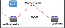
MACsec Proxy For VXLAN
The MACsec Proxy for VXLAN feature enables the MACsec service over VXLAN. MACsec over VXLAN is provided by mapping a Visual Networking Index (VNI), Remote VXLAN Tunnel Endpoint (VTEP) IP to a MACsec proxy subinterface.
Any packets routed to the MACsec proxy subinterface are encrypted and tunneled to the remote VTEP. On the receiving path, the packets are decrypted, then decapsulated, and forwarded. MKA negotiates and renews the encryption keys. For this purpose, a MACsec-capable front panel port has to be dedicated and cannot be plugged in, as it will be used to recycle packets being encrypted and decrypted.
Configuring MACsec Proxy For VXLAN
- 7280SRAM-48C6
- 7280CR2M-30
- 7500R2M-36CQ-LC
The mandatory steps to configure a MACsec proxy sub-interface on an Arista switch are:
Displaying MACsec Proxy For VXLAN Information
Use show mac security interface command to display the proxy sub-interface information.
- Use show mac security mka counters command to display the MACsec counters and detailed values.
switch(config)# show mac security interface Interface SCI Controlled Port Key in Use Ethernet4/1/1 28:99:3a:82:6f:82::605 True 9d5bc0d3076ea4a08b99b9d9:1 Ethernet4/3/1 28:99:3a:82:6f:85::613 True 9d5bc0d3076ea4a08b99b9d9:1 -
switch(config)# show mac security mka counters Interface Rx Success Rx Failure Tx Success Tx Failure Ethernet4/1/1 287 0 288 0 Ethernet4/3/1 288 0 287 0 switch(config)# show mac security mka counters ethernet 49/1.1 detail Interface: Ethernet49/1.1 Tx packet success: 84 Tx packet failure: 0 Tx invalid: 0 Rx packet success: 82 Rx packet failure: 0 Rx invalid: 0 Rx eapol error: 0 Rx basic parameter set error: 0 Rx unrecognized CKN error: 0 Rx ICV validation error: 0 Rx live peer list error: 0 Rx potential peer list error: 0 Rx SAK use set error: 0 Rx distributed SAK set error: 0 Rx distributed CAK set error: 0 Rx ICV Indicator error: 0 Rx unrecognized parameter set error: 0
Limitations
The following limitations may apply when using this feature:
- An interface that switches from allowing unprotected traffic to allowing only protected traffic can experience a traffic disruption of up to 4 seconds.
- If the key server interface manages to establish an MKA session with its old credentials (CKN/CAK pair) while allowing unprotected traffic, a traffic disruption lasting up to 6 seconds may occur in addition to the duration mentioned earlier.
MACsec Fallback to Unprotected Traffic
When MACsec is enabled on an interface, it tries to establish MACsec Key Agreement ( MKA ) session(s) with its peer. If there are no successfully established MKA sessions, the interface can continue to protect the traffic with the last known negotiated key, and if such a key does not exist, it blocks the traffic. The MACsec Fallback to Unprotected Traffic feature introduces an optional configuration which, if provided, allows unprotected traffic whenever there is no successful MKA session with the peer in the following scenarios:
- If MACsec is enabled on an interface with this feature configured, the interface allows unprotected traffic immediately without waiting for the establishment of an MKA session.
- If a MACsec-enabled interface was blocking traffic because no MKA sessions were established, and its corresponding MACsec profile is changed to enable this feature, the interface will start allowing unprotected traffic immediately.
- If a MACsec-enabled interface previously allowed unprotected traffic and its corresponding MACsec profile is changed to disable this feature, the interface will block traffic immediately.
- While an interface is allowing unprotected traffic, it will stop doing so when a new Secure Association Key (SAK) is generated (if this interface is the key server) or when a SAK is received from the key server (if this interface is not the key server).
- If MACsec Fallback to Unprotected Traffic is configured and all MKA sessions between the peers fail, the peers will switch to unprotected traffic. If not configured, protected traffic could have continued with the last known negotiated key.
Primary MKA session-derived keys are prioritized over fallback MKA sessions to protect traffic between pairs. With this feature enabled, the priority order of traffic between peers is:
- Protected using derived keys from primary MKA sessions.
- Protected using derived keys from Fallback MKA sessions.
- Unprotected traffic.
MACsec Fallback to Unprotected Traffic feature Interaction
This feature interacts with other related features in the following way:
- MACsec EAP-FAST Support: The feature configuration has no effect if using dynamic MAC Security keys (derived from 802.1X authentication).
- MACsec Proxy Interfaces: This feature does not work with MACsec proxy subinterfaces.
- Key Retirement Immediate: When configuring this feature with the Key Retirement Immediate feature on an interface, the transition between unprotected and protected traffic may become more frequent. This is because with the Key Retirement Immediate feature, the existing successful MKA session corresponding to the old key is not maintained whenever a new key is configured.
Limitations
The following limitations may apply when using this feature:
- An interface that switches from allowing unprotected traffic to allowing only protected traffic can experience a traffic disruption of up to 4 seconds.
- If the key server interface manages to establish an MKA session with its old credentials (CKN/CAK pair) while allowing unprotected traffic, a traffic disruption lasting up to 6 seconds may occur in addition to the duration mentioned earlier.
Configuring MACsec Fallback to Unprotected Traffic
eos supports this feature on all MACsec capable cards except the 7500E-6CFPX-LC.
The MACsec Fallback to Unprotected Traffic feature is configured under MACsec profile mode using the traffic unprotected allow command. The no form of the command removes the configuration from the switch. This configuration must be present in both the peers for the unprotected traffic to flow between them successfully.
switch(config-mac-security-profile-sampleProfile)# no traffic unprotected allow
Displaying MACsec Fallback to Unprotected Traffic Information
The show mac security interface detail command can be used to verify if the interface is currently allowing unprotected traffic.
switch# show mac security interface Ethernet 6/1/1 detail
Interface: Ethernet4/1/1
SCI: 28:99:3a:82:6f:82::605
SSCI: 00000002
Controlled port: True
Key server priority: 16
Session rekey period: 0
Traffic: Unprotected
Key in use: 9d5bc0d3076ea4a08b99b9d9:1
Latest key: None
Old key: 9d5bc0d3076ea4a08b99b9d9:1(RT)
Interface: Ethernet4/3/1
SCI: 28:99:3a:82:6f:85::613
SSCI: 00000001
Controlled port: True
Key server priority: 16
Session rekey period: 0
Traffic: Protected
Key in use: 9d5bc0d3076ea4a08b99b9d9:1
Latest key: None
Old key: 9d5bc0d3076ea4a08b99b9d9:1(RT)
MACsec Commands
MACsec Configuration Commands
MACsec Profile on a Subinterface
MACsec Show Commands
MACsec EAP FAST Support Commands
an (MACsec)
Command Mode
MAC Security Profile SAK Static Secure Channel Configuration
Command Syntax
an an_number key key_type key_string
no an an_number
default an an_number
- an_number The Association Number. For the Rx channel, values range from 0 to 3. For the Tx channel, the only allowed value is 0. There is no default value.
- key_type The type of string specifying the SAK. There are three valid key types:
- 0 indicates that the key string which follows is not encrypted.
- 7 indicates that the key string which follows is hidden or obfuscated.
- 8a The following key is encrypted with AES-256-GCM.
- key_string The Secure Association Key itself, in hexadecimal octets.
switch(config)# mac security
switch(config-mac-security)# profile test
switch(config-mac-security-profile-test)# key source sak static
switch(config-mac-security-profile-test-sak-static)# secure channel rx
switch(config-mac-security-profile-test-sak-static-rx)# an 1 key 0 11112222333344445555666677778888
switch(config-mac-security-profile-test-sak-static-rx)#cipher
The cipher command configures the cipher authentication for MAC security on the switch.
Command Mode
MACsec Profile
Command Syntax
cipher encryption_standard
Parameters
- aes128-gcm-xpn Advanced Encryption Standard (128-bit, Galois/Counter mode, Extended Packet Numbering).
- aes256-gcm-xpn Advanced Encryption Standard (256-bit, Galois/Counter mode, Extended Packet Numbering).
Example
switch(config-mac-security-profile-test)# cipher aes128-gcm-xpn
switch(config-mac-security-profile-test)#dot1x pae supplicant
The dot1x pae supplicant command applies the supplicant profile by enabling it on the Mac Security interface.
Command Mode
Interface Configuration
Command Syntax
dot1x pae supplicant
Example
switch(config-if-Et6/1)# dot1x pae supplicant testdot1x timeout reauth-timeout-ignore always
The dot1x timeout reauth-timeout-ignore always command retains the current port state without blocking it, irrespective of when the authentication server is unreachable or in case of supplicant timeouts.
Command Mode
Interface Configuration
Command Syntax
dot1x timeout reauth-timeout-ignore always
Example
switch(config-if-Et6/1)# dot1x timeout reauth-timeout-ignore alwaysdot1x
The dot1x command places the switch in the dot1x mode. In this mode, the user is allowed to configure various MACsec configurations.
Command Mode
Global Configuration
Command Syntax
dot1x
Example
switch(config)# dot1x
switch(config-dot1x)#entropy source hardware
The entropy source hardware command generates the cryptographic keys to strengthen the random number generator used by MACsec.
Command Mode
Management Configuration
Command Syntax
entropy source hardware
Example
switch(config)# management security
switch(config-mgmt-security)# entropy source hardwareidentifier (MACsec)
Command Mode
MAC Security Profile SAK Static Secure Channel Configuration
Command Syntax
identifier MAC_address
no identifier
default identifier
Parameter
MAC_address The MAC address identifying the secure channel.
Example
switch(config)# mac security
switch(config-mac-security)# profile test
switch(config-mac-security-profile-test)# key source sak static
switch(config-mac-security-profile-test-sak-static)# secure channel rx
switch(config-mac-security-profile-test-sak-static-rx)# identifier 01:02:03:04:05:06::1234
switch(config-mac-security-profile-test-sak-static-rx)#key (MACsec)
The key command configuresthe primary key to activate the MACsec profile
Command Mode
MACsec Profile Configuration
Command Syntax
key <options>
- CKN Connectivity association key name in hex octets. Options include:
- 0Specifies that an UNENCRYPTED key will follow.
- 7Specifies that an HIDDEN key will follow.
- CAKConnectivity association key in hex octets.
- fallback Configure the key as a fallback.
- retirement Retire the key. Options include:
- immediate Retire the key immediately.
- immediate Retire the key immediately.
- source List of sources to derive MAC security keys. Options include:
- dot1xDerive MAC security keys from IEEE 802.1X-based port authentication
- group-cak Derive MAC security keys from Group CAK Distribution.
- sak static Enter
- The following example configures the primary key for the sample profile for MAC security on the switch.
switch(config)# mac security switch(config-mac-security)# profile sample_Profile switch(config-mac-security-profile-sample_Profile)# key 0abcd1 0 1234abcd - The following example configures the fallback CAK on a profile.
switch(config)# mac security switch(config-mac-security)# profile sample_Profile switch(config-mac-security-profile-sample_Profile)# key 0abcd1 0 1234abcd fallback
key retirement immediate
The key retirement immediate command configures the key retirement feature on the key server and assists the key server to decide the principal actor for SAK distribution by triggering the re-election of principal actor immediately. It is recommended that the key retirement is configured on both key server and non key server peers.
The no key retirement immediate command disable the key retirement function by removing the key retirement immediate command from the running-config.
Command Mode
MACsec Profile
Command Syntax
key retirement immediate
Example
switch(config)# mac security
switch(config-mac-security)# profile sample
switch(config-mac-security-profile-sample)# key retirement immediatelicense (Global Mode)
The license command configures eos licenses on the switch under the global configuration mode. These licenses include the MACsec license.
Command Mode
Global Configuration
Command Syntax
license [[import URL] | update]
Parameters
- import Import license from a URL.
- URL The URL from which to import a license.
- update Trigger a check for licenses.
Example
switch# license import flash:eosLic-1.json
switch#license (MACsec)
The license command configures the MACsec license on the switch under the MAC Security configuration mode using a hex key.
The no license and default license commands delete the current license from running-config.
Command Mode
MAC Security
Command Syntax
license licensee_name license_value
Parameters
- licensee_name Name of the licensee.
- license_value 8 digit hexadecimal key to authorize MAC security.
Example
switch(config)# mac security
switch(config-mac-security)# license Test-LICNC AABBCCDD
switch(config-mac-security)#
l2-protocol
The command l2-protocol configures the Layer 2 protocol processing for MACsec. The no l2-protocol and the default l2-protocol remove the command from the configuration.
Command Mode
MAC Security Configuration
Command Syntax
l2-protocol ethernet-flow-control [bypass | encrypt]
no l2-protocol ethernet-flow-control [bypass | encrypt]
default l2-protocol ethernet-flow-control [bypass | encrypt]
Parameters
- ethernet-flow-control - Configures Ethernet Flow Control frame processing for MAC security.
- bypass - Transmit frames without processing them.
- encrypt - Transmit and receive frames with protection.
Example
The following example configures MAC security with L2 protocol and Ethernet Flow Control bypassing frame protection:
switch(config)# mac-security
switch(config-mac-security)# l2 protocol ethernet-flow-control bypassmac security
The mac security command enables MAC security provision on the switch.
The no mac security and default mac security commands restore the switch to its default state by removing the corresponding mac security command from running-config.
Command Mode
Global Configuration
Command Syntax
mac security
no mac security
default mac security
Example
switch(config)# mac security
switch(config-mac-security)#mac security profile
The mac security profile command applies a MACsec profile to an interface or subinterface.
The no mac security profile and default mac security profile commands remove the MACsec profile, disabling MACsec on the configuration-mode interface.
Command Mode
Interface Ethernet Configuration Mode
Command Syntax
mac security profile profile-name
no mac security profile profile-name
default mac security profile profile-name
Parameter
profile-name the MACsec profile name.
Example
switch(config)# interface ethernet1
switch(config-if-Et1)# no switchport
switch(config-if-Et1)# interface ethernet1.10
switch(config-if-Et1.10)# encapsulation dot1q vlan 20
switch(config-if-Et1.10)# mac security profile test-profilemka key-server
The mka key-server command configures key server among the MACsec peers.
Command Mode
MACsec Profile Configuration
Command Syntax
mka key-server [priority value]
Parameters
- priority MKA key server priority.
- value Key server priority value. Value ranges from 0 to 255.
Example
switch(config)# mac security
switch(config-mac-security)# profile sample_Profile
switch(config-mac-security-sample_Profile)# mka key-server priority 10mka session
The mka session command configures period at which the SAK is refreshed .
Command Mode
MACsec Profile Configuration
Command Syntax
mka session [rekey-period value]
Parameters
- rekey-period Sets MKA session re-key period.
- value Session re-key period in seconds. Value ranges from 30 to 100000.
Example
switch(config)# mac security
switch(config-mac-security)# profile sample_Profile
switch(config-mac-security-sample_Profile)# mka session rekey-period 10profile (MACsec)
The profile command places the switch in MAC Security Profile configuration mode and creates a MACsec profile if a profile of the specified name does not already exist. MACsec profiles contain the configuration information needed to establish a MACsec connection, and are applied to interfaces using the mac security profile command.
Command Mode
MAC Security Configuration
Command Syntax
profile profile-name
Parameter
profile-name Name of the MACsec profile.
Example
switch(config)# mac security
switch(config-mac-security)# profile test
switch(config-mac-security-profile-test)#replay
The replay command configures the action to be taken when packets received are not in order, based on their packet numbers. The window size in replay protection specifies the window size within which out-of-order packets are allowed. This command is configured under the MACsec Profile configuration mode.
The no and default form of the command removes all the configurations related to replay command from the running configuration on the switch.
Command Mode
MACsec Profile
Command Syntax
replay protection {disabled | window window_size}
no replay protection {disabled | window window_size}
default replay protection {disabled | window window_size}
Parameters
- protection Specifies the action to be taken when packets received are not in order, based on their packet numbers..
- disabled Disables replay protection.
- window Specifies the allowable window within which an out-of-order packet can be received.
- window_size The allowable value ranges from 0 tthrough 4294967295.
- window_size The allowable value ranges from 0 tthrough 4294967295.
Example
switch(config)# mac security
switch(config-mac-security)# profile TEST
switch(config-mac-security-profile-TEST)# replay protection window 100sci
The sci command add a Secure Channel Identifier (SCI) in data packets for MACsec on the switch. Each MACsec device has a Secure Channel (SC) used to send traffic to other device. Each channel has an 8-byte Secure Channel Identifier (SCI). The first 6 bytes match the MAC address of the device transmitting through that channel. The remaining 2 bytes are a Port Identifier used to distinguish between multiple channels from the same device. The command is configured under the MACsec profile configuration mode.
Command Mode
MACsec Profile
Command Syntax
sci
Example
switch(config)# mac security
switch(config-mac-security)# profile TEST
switch(config-mac-security-profile-TEST)# scisecure channel (MACsec)
Command Mode
MAC Security Profile Static SAK Configuration Mode
Command Syntax
secure channel {Rx|Tx}
- Rx Enter the configuration mode for the Rx channel.
- Tx Enter the configuration mode for the Tx channel.
Example
switch(config)# mac security
switch(config-mac-security)# profile test
switch(config-mac-security-profile-test)# key source sak static
switch(config-mac-security-profile-test-sak-static)# secure channel tx
switch(config-mac-security-profile-test-sak-static-sc-tx)#show dot1x supplicant
The show dot1x supplicant command displays the 802.1X supplicant status.
Command Mode
EXEC
Command Syntax
show dot1x supplicant
Example
switch# show dot1x supplicant
Interface: Ethernet6/1
Identity: arastra
EAP method: fast
Status: success
Supplicant MAC: 44:4c:a8:34:bf:20
Authenticator MAC: 00:1c:73:e0:d3:76
- Interface: The port on which the supplicant is running.
- Identity: Configured supplicant identity.
- EAP method: Configured EAP method (Currently just EAP-FAST).
- Status: Supplicant Status. Can be one of the following:
- Success Authentication has been successful.
- Down Authentication sequence has not begun.
- Failed Authentication has failed.
- Connecting Authentication is in progress.
- Unused Supplicant is uninitialized.
- Supplicant MAC: MAC address of the supplicant.
- Authenticator MAC: MAC address of the authenticator (peer). Existing Mac Security show commands can be used to look at Mac Security status.
show mac security counters detail
The show mac security counters detail command to displays the detail information about the MACsec security counters.
Command Mode
EXEC
Command Syntax
show mac security counters detail
Example
switch# show mac security counters detail
Ethernet4/1/1 Counter Name Count
-------------------------------------------------------
outPktsEncrypted 112
outOctetsEncrypted 11984
outPktsUntagged 0
outPktsTooLong 0
outPktCtrl 224
inPktsDecrypted 2
inOctetsDecrypted 214
inPktsUnchecked 0
inPktsOK 2
inPktsNotValid 0
inPktsNotUsingSA 0
inPktsCtrl 223
inPktsNoTag 8
inPktsTagged 0
inPktsBadTag 0
inPktsNoSCI 0
inPktsLate 0
Ethernet4/3/1 Counter Name Count
-------------------------------------------------------
outPktsEncrypted 2
outOctetsEncrypted 214
outPktsUntagged 0
outPktsTooLong 0
outPktCtrl 223
inPktsDecrypted 111
inOctetsDecrypted 11877
inPktsUnchecked 0
inPktsOK 111
inPktsNotValid 0
inPktsNotUsingSA 0
inPktsCtrl 224
inPktsNoTag 9
inPktsTagged 0
inPktsBadTag 0
inPktsNoSCI 0
inPktsLate 0show mac security counters
The show mac security counters command to displays information about the MACsec security counters.
Command Mode
EXEC
Command Syntax
show mac security counters
Example
switch# show mac security counters
Port InPktsDecrypted InOctetsDecrypted OutPktsEncrypted OutOctetsEncrypted
Et4/1/1 2 214 109 11663
Et4/3/1 109 11663 2 214show mac security interface detail
The show mac security interface detail command displays the detail information about the MACsec on the interface.
Command Mode
EXEC
Command Syntax
show mac security interface detail
Example
switch# show mac security interface detail
Interface: Ethernet4/1/1
SCI: 28:99:3a:82:6f:82::605
SSCI: 00000002
Controlled port: True
Key server priority: 16
Session rekey period: 0
Traffic: Protected
Key in use: 9d5bc0d3076ea4a08b99b9d9:1
Latest key: None
Old key: 9d5bc0d3076ea4a08b99b9d9:1(RT)
Interface: Ethernet4/3/1
SCI: 28:99:3a:82:6f:85::613
SSCI: 00000001
Controlled port: True
Key server priority: 16
Session rekey period: 0
Traffic: Protected
Key in use: 9d5bc0d3076ea4a08b99b9d9:1
Latest key: None
Old key: 9d5bc0d3076ea4a08b99b9d9:1(RT)
About the Output
- Interface: Name of the interface.
- Secure Channel Identifier (SCI): Combination of MAC address and port number. Used to uniquely identify a Mac Security port.
- Controlled Port: Indicates if Mac Security is enabled on the port. A value of True indicates that encryption is enabled on the port.
- Key In Use: The SAK identifier currently in use. Combination of Key Servers message identifier (see below) and key number.
- Key Server priority: Configured key server priority.
- Session Rekey Period: Configured session rekey period.
- Latest Key: Latest SAK being negotiated by Mac Security Key Agreement Protocol (MKA).
-
Old Key: The last SAK negotiated by Mac Security Key Agreement Protocol (MKA).
Note: Latest and Old key are MKA protocol specific terminology and are used to refer to the last two keys in use. For all practical purposes, Key In Use field is used to identify the current key.
show mac security interface
The show mac security interface command shows information aboutMACsec on the interface.
Command Mode
EXEC
Command Syntax
show mac security interface
Examples
- The following example displays information about MACsec on the interface.
switch# show mac security interface Interface SCI Controlled Port Key in Use Ethernet4/1/1 28:99:3a:82:6f:82::605 True 9d5bc0d3076ea4a08b99b9d9:1 Ethernet4/3/1 28:99:3a:82:6f:85::613 True 9d5bc0d3076ea4a08b99b9d9:1 switch# - The following example displays the association numbers (ANs) of SAKs for both Rx and Tx on the interface Ethernet9/1. Actual SAK values are never displayed in show command output.
switch# show mac security interface Interface SCI Controlled Port Key in Use Ethernet9/1 01:02:03:04:05:06::1235 True static SAK: Rx AN: 0,1 Tx AN: 0 switch# - The following example displays MACsec information for a unidirectional link. On the Rx side, the SCI is shown as 00:00:00:00:00:00::0, and only the Rx AN is shown.
switch# show mac security interface Interface SCI Controlled Port Key in Use Ethernet9/1 00:00:00:00:00:00::0000 True static SAK: Rx AN: 0 switch# - The following example displays MACsec information on the Tx side of a unidirectional link. In this case, the configured SCI is shown, along with the Tx AN.
switch(config)# show mac security interface Interface SCI Controlled Port Key in Use Ethernet9/1 01:02:03:04:05:06::1235 True static SAK: Tx AN: 0
show mac security mka counters
The show mac security mka counters command to display information about the MACsec MKA counters.
Command Mode
EXEC
Command Syntax
show mac security mka counters
Example
switch# show mac security mka counters
Interface Rx Success Rx Failure Tx Success Tx Failure
Ethernet4/1/1 287 0 288 0
Ethernet4/3/1 288 0 287 00show mac security participants detail
The show mac security participants detail command displays detail information about the MACsec participants.
Command Mode
EXEC
Command Syntax
show mac security participants detail
Example
switch# show mac security participants detail
Interface: Ethernet4/1/1
CKN: abcd
Message ID: 9d5bc0d3076ea4a08b99b9d9
Elected self: True
Success: True
Principal: True
Default: False
KeyServer SCI: 28:99:3a:82:6f:82::605
SAK transmit: True
LLPN exhaustion: 0
Distributed key identifier: 9d5bc0d3076ea4a08b99b9d9:1
Live peer list: ['c79ad8882c2dd3a8e838a691']
Potential peer list: []
CKN: dead
Message ID: 4ef4cf009161bd551b5e7434
Elected self: True
Success: True
Principal: False
Default: True
KeyServer SCI: 28:99:3a:82:6f:82::605
SAK transmit: False
LLPN exhaustion: 0
Distributed key identifier: None
Live peer list: ['3dfd4486b5f68a81014a37ec']
Potential peer list: []
Interface: Ethernet4/3/1
CKN: abcd
Message ID: c79ad8882c2dd3a8e838a691
Elected self: False
Success: True
Principal: True
Default: False
KeyServer SCI: 28:99:3a:82:6f:82::605
SAK transmit: True
LLPN exhaustion: 0
Distributed key identifier: 9d5bc0d3076ea4a08b99b9d9:1
Live peer list: ['9d5bc0d3076ea4a08b99b9d9']
Potential peer list: []
CKN: dead
Message ID: 3dfd4486b5f68a81014a37ec
Elected self: False
Success: True
Principal: False
Default: True
KeyServer SCI: 28:99:3a:82:6f:82::605
SAK transmit: False
LLPN exhaustion: 0
Distributed key identifier: None
Live peer list: ['4ef4cf009161bd551b5e7434']
Potential peer list:
About the Output
- Connectivity Association Key Name (CKN): Configured name of the key in use.
- Message ID: A random 92 bit string used as an identifier for an MKA participant.
- Elected Self: True if this participant is the elected key server.
- Success: True if this participant is live and has at least one live peer.
- Principal: True if this participant is the principal participant elected to distribute SAKs.
- Default: True if this participant is a fallback/backup participant (spawned when a fallback key is configured in a Mac Security profile).
- Key Server SCI: The SCI of the key server.
- SAK Transmit: True if the participant is ready to use the negotiated key for transmit.
- LLPN Exhaustion: Increments if the number of data packets sent using the current key exceeds a certain threshold. Because we use a 64 bit packet number cipher suite, this should never increment.
- Distributed Key Identifier: Message ID + key number of the most recently generated SAK.
show mac security participants
The show mac security participants interface command displays information about the MACsec participants.
Command Mode
EXEC
Command Syntax
show mac security interface
Example
switch# show mac security participants
Interface: Ethernet4/1/1
    CKN: abcd
      Message ID: 9d5bc0d3076ea4a08b99b9d9
      Elected self: True
      Success: True
      Principal: True
      Default: False

    CKN: dead
      Message ID: 4ef4cf009161bd551b5e7434
      Elected self: True
      Success: True
      Principal: False
      Default: True

Interface: Ethernet4/3/1
    CKN: abcd
      Message ID: c79ad8882c2dd3a8e838a691
      Elected self: False
      Success: True
      Principal: True
      Default: False

    CKN: dead
      Message ID: 3dfd4486b5f68a81014a37ec
      Elected self: False
      Success: True
      Principal: False
Default: Trueshow mac security profile
Command Mode
EXEC
Command Syntax
show mac security profile [profile_name]
Parameters
profile_name The MACsec profile to show information about.
Example
switch# show mac security profile
Profile: test
Cipher: aes256-gcm-xpn
Primary CKN:
Primary CAK SHA-256 hash:
Fallback CKN:
Fallback CAK SHA-256 hash:
Source: cli
Priority: 100
SCI Inclusion: disabled
Key retirement policy: delayed
Unprotected traffic policy: allow active-sak
MKA lifetime: 6 seconds
MKA key server priority: 16
Session rekey period: 0
Bypassed protocols:
Max AN value of SAK: 3
Configured on:
switch#show mac security sak
- The name of the Ethernet interface.
- The installed SAK IDs.
- The SAK profile name.
- The total number of SAKs generated.
- The number of SAKs generated due to a new live peer.
- The number of SAKs generated due to a rekey timer.
- The number of SAKs generated due to packet number exhaustion.
- The SAK installation time in seconds in each direction.
- The number of forced new Tx SAK installations.
Command Mode
EXEC
Command Syntax
show mac security sak [interface ethernet Ethernet_interface]
Parameters
interface ethernet Show SAK status information about the specified Ethernet interface. If this option is omitted, information for all Ethernet interfaces is shown.
Ethernet_interface The Ethernet interface to show SAK status for.
Example
switch(config-mac-security-profile-test)# show mac security sak
Interface: Ethernet9/1
Installed SAK ID: static SAK: Rx AN: 0,1 Tx AN: 0
Installed SAK from: static-SA
Total SAK generated: 0
SAK generated due to new live peer: 0
SAK generated due to rekey timer: 0
SAK generated due to packet number exhaustion: 0
SAK installation time( in seconds ):
Direction 0-1 1-2 2-3 3+
---------- ----- ----- ----- -----
Rx 1 0 0 0
Tx 1 0 0 0
Maximum Rx installation time: 0.0884998080001 seconds
Maximum Tx installation time: 0.0884941590002 seconds
Forced new Tx SAK installation count: 0show mac security status
The show mac security status command displays the MACsec status information on a switch.
Command Mode
EXEC
Command Syntax
show mac security status
Example
switch# show mac security status
Active Profiles: 1
Data Delay Protection: No
FIPS Mode: No
Secured Interfaces: 2
License: Enabledsupplicant profile
The supplicant profile command configures the supplicant profile containing all the credentials necessary for 802.1X authentication to succeed.
Command Mode
dot1x Configuration
Command Syntax
supplicant profile profile_name options
- profile_name Name of the supplicant profile.
- The following parameters can be included after entering the profile mode:
- eap-method Extensible Authentication Protocol (EAP) method. Option include:
- fastEAP Flexible Authentication via Secure Tunneling (FAST).
- identity Extensible Authentication Protocol (EAP) user identity. Option include:
- WORD User identity name.
- WORD User identity name.
- passphrase Extensible Authentication Protocol (EAP) password. Options include:
- 0 Specifies that an UNENCRYPTED key will follow.
- 7 Specifies that an HIDDEN key will follow.
- LINE The UNENCRYPTED (clear-text) shared key.
- eap-method Extensible Authentication Protocol (EAP) method. Option include:
- The following commands place the switch in the supplicant profile mode.
switch(config)# dot1x switch(config-dot1x)# supplicant profile test switch(config-dot1x-supp-profile-test)# - The following commands configures the EAP FAST method for the supplicant profile called test profile for MAC security on the switch.
switch(config)# dot1x switch(config-dot1x)# supplicant profile test switch(config-dot1x-supp-profile-test)#eap-method fast - The following commands configures the Identity for the supplicant profile called test profile for MAC security on the switch.
switch(config)# dot1x switch(config-dot1x)# supplicant profile test switch(config-dot1x-supp-profile-test)# identity New_User - The following commands configures the passphrase for the supplicant profile called test profile for MAC security on the switch.
switch(config)# dot1x
switch(config-dot1x)# supplicant profile test
switch(config-dot1x-supp-profile-test)# passphrase 7 070E334D5D1D0B04
traffic unprotected allow
The traffic unprotected allow command configures the switch to allow the unprotected traffic whenever there is no successful MKA session established with the peer.
The no traffic unprotected allow command disable the MACsec Fallback to Unprotected Traffic function by removing the traffic unprotected allow command from running-config.
Command Mode
MACsec Profile
Command Syntax
traffic unprotected allow
no traffic unprotected allow
Example
Switch(config)# mac security
Switch(config-mac-security)# profile sample
Switch(config-mac-security-profile-sample)# no traffic unprotected allow
Internet Protocol Security (IPsec)
IPsec Introduction
Internet Protocol Security (IPsec) is a protocol suite for securing Internet Protocol (IP) communications by authenticating and encrypting each IP packet of a communication session. IPsec includes protocols for establishing mutual authentication between agents periodically during the session and negotiation of cryptographic keys to be used during the session. IPsec supports network-level peer authentication, data origin authentication, data integrity, data confidentiality (encryption), and replay protection.
IPsec protects data traffic between sites, such as between an enterprise's Branch, HQ, and Data center sites.
IPsec uses the following protocols to perform various functions:
- Authentication Headers (AH) provide connectionless integrity and data origin authentication for IP datagrams and protect against replay attacks.
- Encapsulating Security Payloads (ESP) provides confidentiality, data origin authentication, connectionless integrity, and an anti-replay service (a form of partial sequence integrity).
- Internet Key Exchange (IKE) is a key management protocol that provides security for virtual private networks (VPNs) negotiations and network access to random hosts. It is also described as a method for exchanging keys for encryption and authentication over an unsecured medium, such as the Internet.
IPsec Overview
Security Associations
Security Associations (SA) provide the bundle of algorithms and data that provide the parameters necessary for AH and ESP operations. The Internet Security Association and Key Management Protocol (ISAKMP) provides a framework for authentication and key exchange, with actual authenticated keying material provided by manual configuration with pre-shared keys, Internet Key Exchange (IKE and IKEv2), and other mechanisms.
IPsec uses the Security Parameter Index (SPI) and the destination address in the packet header to determine the necessary protection for an outgoing packet. The SPI is an index to the security association database (SADB). The SPI uniquely identifies a security association for the packet in combination with the destination address.
The system performs a similar procedure for an incoming packet, where IPsec gathers decryption and verification keys from the security association database.
Full bidirectional communication requires at least two SAs, one for each direction. The following parameters define SA:
- Security Algorithms (AH) or Encapsulating Security Payloads (ESP) and keys.
- Mode: Tunnel or Transport.
- Key Management Method: Manual or IKE.
- Lifetime: Expressed in hours or minutes (minimum configurable value is 10 minutes).
Mode of Operation
IPsec on Arista switches operates in tunnel mode. In tunnel mode, the entire IP packet is encrypted and authenticated, then encapsulated into a new IP packet with a new IP header.
IPsec uses tunnel mode to create virtual private networks (VPN) for network-to-network communications, such as secure connections between routers across different sites. Tunnel mode serves as the foundation for the majority of network-to-network IPsec implementations.
Key Management
Key management on Arista switches uses the Internet Key Exchange (IKE) method. Internet Key Exchange (IKE) supports automated generation and renegotiation of SAs (includes keys) between the devices at a configured interval, making it much more scalable and secure.
IPsec needs SAs to define the algorithms and keys to protect traffic. IKE establishes the SA so IPsec can protect traffic.
There are two IKE versions, IKEv1 and IKEv2. IKEv2 builds on IKEv1, but both are still widely used today.
IKEv1
- IKEv1 Phase 1
- IKEv1 Phase 2
IKEv1 Phase 1
- Uses main or aggressive mode exchange
- Negotiates IKE SA
- Used for control plane
- Peer authentication
- Uses quick mode exchange
- Negotiates IPsec SAs
- Encryption algorithm
- Hash MAC (HMAC) algorithm
- Peer authentication procedure
- Diffie-Hellman group for initial key exchange
- SA lifetime
IKE initially performs a Diffie-Hellman (DH) exchange at the start of the IKE session. A Diffie-Hellman (DH) exchange allows participants to produce a shared secret value. The strength of the technique is that it allows participants to create the secret value over an unsecured medium without passing the secret value through the wire. From that exchange, peers get shared keying material, which is then used for IKE encryption and integrity functions. The strength of that keying material is that it can be used for faster performance by choosing lower key sizes for Diffie-Hellman exchanges. Diffie-Hellman exchanges' key length (strength) can be changed using different DH groups.
When an IKE session's lifetime expires, a new Diffie-Hellman exchange is performed between peers, and the IKE SA is re-established.
The IPsec protection policy, resulting in IPsec SAs, defines network traffic protection. These IPsec SAs are usually negotiated over IKE sessions. The parameters that define the IPsec protection policy are:
- Encryption Algorithm
- Hash MAC (HMAC) Algorithm
The key material for IPsec SA (also called Child SA) is derived from keying material from IKEv1 phase 1.
- Main Mode
- 6 packet exchange
- Full identity protection and better anti-DoS protection
- Aggressive Mode
- 3 packet faster session establishment
- Identities are exchanged in clear
- Weak DoS protection
Authentication
- Pre-Shared Keys (PSK): As the name suggests, a shared secret is distributed out-of-band to the peers. The peers use this information and nonce parameters to create a hash to authenticate messages.
- PKI Certificates: Here, peers' certificates are exchanged, and hashes are calculated over these certificates to authenticate each other.
IKEv2
IKEv2 differs from IKEv1 in the following ways:
- Faster set up because of the reduced number of messages.
- More secure.
- ESP is reused for all IKEv2 messages.
- Suite-B support.
- There is no aggressive mode, so IKEv2 always provides identity protection.
- Additional authentication methods.
- Local and remote can use different authentication methods and use different pre-shared keys.
- Authentication is done unidirectionally in IKEv2.
Route-based VPN
A route-based VPN employs routed tunnel interfaces as the virtual network's endpoints. All traffic passing through a tunnel interface traverses the VPN. Rather than relying on an explicit policy to dictate which traffic enters the VPN, static and dynamic IP routes are formed to direct the desired traffic through the VPN tunnel interface.
Since route-based VPNs support dynamic routing information through VPN tunnels, eos supports only route-based VPNs for dynamic routing support and easier configuration and management.
In route-based VPN, features like NAT, ACL, and QoS are applied to packets before they are encrypted by applying these features to the tunnel interface and can be applied to encrypted packets by applying these features on the physical interface carrying the tunnel traffic.
Virtual Template Interface (VTI)
A new tunnel interface type, vti, represents the VPN tunnel. This tunnel interface will participate in the routing, and any packets forwarded to it will be encrypted and forwarded to the other end of the tunnel. Note that this does not add a new header to the packet.
Configuring IPsec
Complete the following steps to configure IPsec tunnels over the switch.
This configuration uses the default IKE version 2 procedure.
Displaying IPsec Information
- Use the show ip security policy command to display the IPsec policy information.
switch# show ip security policy Policy Name Authentication Encryption Integrity Lifetime Rekey DH Group ike-policy Pre-shared 256-bit AES 256bit Hash 8 hours False 3072 bit - Use the show ip security profile command to display the IP security profile information.
switch# show ip security profile
Profile name      IKE Policy Name      SA
ipsec-profile     ike-policy           sa-policy
Configuring PKI
Configure PKI as a certificate-based authentication for the IPsec protocol.
Enabling PKI for an IKE Policy
Configure the authentication mode as PKI for the IKE policy. The IPsec refers to this policy when using PKI authentication.
Use the following commands to enable PKI authentication for the IKE policy, MyPKI:
switch(config)#ip security
switch(config-ipsec)#ike policy MyPolicy
switch(config-ipsec)#authentication pki
switch(config-ipsec)#exit
switch(config-ipsec)#show active
    ip security
    ike policy MyPolicy
    authentication pki
Configuring the PKI Profile
Configure the PKI profile used by an IPsec profile. This profile refers to the SSL profile for authentication.
switch(config)#ip security
switch(config-ipsec)#profile MyProfile
switch(config-ipsec)#pki-profile pki-abc
switch(config-ipsec)#ike-profile MyPKI
switch(config-ipsec)#exit
switch(config-ipsec)#show active
   profile MyProfile
      ...
   ike-policy MyPKI
   pki-profile pki-abc
      ...
 !
When configuring IPsec, consider the following information:
- For PKI, each rekey performs reauthentication.
- DPS paths always use the VTEP-IP as the ID when configuring a local ID for each IKE policy.
- If the IKE policy does not have a local ID, the ID comes from the certificate subject name (SN).
- If the IKE policy has a local ID, the certificate used in the corresponding PKI profile should contain this ID in the Subject Alternative Names (SAN) field. If the local ID contains the FQDN, it must be present in the DNS or email field in the SAN depending on if the FQDN contains a domain address or email-ID.
- Multiple connections on one device can use the same certificate by specifying all of the IDs for each connection in the certificate SAN.
- For tunnels sharing a common endpoint, use different certificates for each tunnel or configure a unique local ID for each tunnel. This avoids duplicate connections.
Displaying PKI IPsec Information
Use the show ip security policy to display the authentication mode for security policies:
switch#show ip security policy
Policy Name               Authentication   Crypto Suite  Encryption    Integrity     Lifetime  Rekey  DH Group
-----------               --------------   ------------  ----------    ---------     --------  -----  --------
a                         Pre-shared        -            128-bit AES   256bit Hash   8 hours   False  3072 bit
MyPKI                     PKI               -            128-bit AES   256bit Hash   8 hours   False  3072 bit
Use the show ip security profile to display information about PKI profile configured for an IPsec profile.
switch#show ip security profile
Profile name              IKE Policy Name           SA                        PKI Profile
-------------            -----------------       ---------                   ------------
MyPKI                    ike-xyz                 sa-xyz                      pki-xyz
IPsec Commands
ike policy
The ike policy command configures the Internet Security Association and Key Management Protocol on the switch and related policies. Configure the IKE policy in IP security configuration mode.
The no ike policy command deletes the IKE policy configuration from the switch.
The exit command returns the switch to the global configuration mode.
Command Mode
IP Security Configuration
Command Syntax
ike policy policy-name
no ike policy policy-name
Parameters
- policy-name - Specify the IKE policy name.
- authentication - Specify the authentication type.
- crypto - Specify a crypto algorithm suite type.
- dh-group - Specify the Diffie-Hellman Group value.
- encryption - Specify the encryption type.
- ike-lifetime - Sets the IkeLifetime for an ISAKMP security association. Specify a value in hours or minutes with a minimum of 10 minutes.
- integrity - Specify the Integrity algorithm.
- local-id - Specify the local IKE identification.
- remote-id - Specify the remote peer IKE identification.
- version - Specify the IKE version.
Example
switch(config)# ip security
switch(config-ipsec)# ike policy MyIKEPolicy
interface tunnel (IPsec)
The interface tunnel command places the switch in the Interface Tunnel Configuration Mode.
Interface tunnel configuration mode does not provide a group change mode. The running-config changes immediately after executing the commands.
The no interface tunnel command deletes the interface tunnel configuration.
The exit command returns the switch to the global configuration mode.
Command Mode
Global Configuration
Command Syntax
interface tunnel value
no interface tunnel value
Parameter
value - Specify the tunnel interface number. The value ranges from 0 to 255.
Example
switch(config)# interface tunnel 10
switch(config-if-Tu10)#
ip security
The ip security command places the switch in the IP Security Configuration Mode.
IP security configuration mode is not a group change mode. The running-config changes immediately after executing the commands.
The no ip security command deletes the IP security configuration.
The exit command returns the switch to the global configuration mode.
Command Mode
Global Configuration
Command Syntax
ip security
no ip security
Example
switch(config)# ip security
switch(config-ipsec)# ike policy IKE1
switch(config-ipsec-IKE1)# exit
switch(config-ipsec)# sa policy SA1
switch(config-SA1)#
profile (IPsec)
The profile command configures the IP security profile on the switch. Configure the profile in IP security configuration mode.
The no profile command deletes the IP security profile configuration from the switch.
The exit command returns the switch to the global configuration mode.
Command Mode
IP Security Configuration
Command Syntax
profile profile-name
no profile profile-name
Parameters
- profile-name Specifies the IP security profile name.
- connection - Specify the type ofIPsec Connection (Initiator/Responder/Dynamic).
- dpd - Specify the Dead Peer Detection in an interval between 2 and 3600 seconds.
- flow - Specify to set the flow in parallel.
- ike-policy- Specify the ISAKMP policy.
- mode- Specify the IP security mode type.
- sa-policy - Specify the name of the security association.
- shared-key - Specify a shared key value.
Example
switch(config)# ip security
switch(config-ipsec)# profile test
switch(config-ipsec-profile)#
sa policy
The sa policy command specifies a Security Association (SA) policy used for IPsec configuration, and enters IP security SA policy configuration mode to configure the named policy.
The no sa policy command deletes the specified SA policy configuration from the switch.
The exit command returns the switch to the global configuration mode.
Command Mode
IP Security Configuration
Command Syntax
sa policy policy_name
no sa policy policy_name
Parameters
- policy_name - Specifies the SA policy name.
- anti-replay - Specify the IPsec duplicate IP datagram detection mode.
- esp - Specify the type of Encapsulation Security Payload.
- pfs - Add Perfect Forward Secrecy.
- sa lifetime - Specify a lifetime for the Security Association. Configure the lifetime in hours or minutes.
Example
switch(config)# sa policy test
switch(config-ipsec-sa)# sa lifetime 30 minutes
show ip security applied-profile
The show ip security applied-profile command displays the IP security profile names and the corresponding interfaces with the profile.
Command Mode
EXEC
Command Syntax
show ip security applied-profile
Example
switch# show ip sec applied-profile
Profile Name                 Interface
ipsec-profile-1              Tunnel1,
                             Tunnel2,
                             Tunnel3,
                             Tunnel4,
                             Tunnel5,
                             Tunnel6,
                             Tunnel7,
                             Tunnel8,
                             Tunnel9,
                             Tunnel10,
                             Tunnel11,
                             Tunnel12,
                             Tunnel13,
                             Tunnel14,
                             Tunnel15,
                             Tunnel16,
                             Tunnel17,
                             Tunnel18,
                             Tunnel19,
                             Tunnel20,
                             Tunnel21,
                             Tunnel22,
                             Tunnel23,
                             Tunnel24,
                             Tunnel25,
                             Tunnel26,
show ip security connection
The show ip security connection command displays the IP security connection status information.
Command Mode
EXEC
Command Syntax
show ip security connection
Example
switch# show ip sec conn tunnel 1
Tunnel   Source     Dest     Status       Uptime     Input    Output        Rekey Time
Tunnel1  11.1.1.1   11.2.1.1 Established  19 hours   0 bytes  0 bytes       4 hours
                                                     0 pkts   62937679 pkts

switch# show ip sec conn tunnel 1 detail
Tunnel1:
   source address 11.1.1.1, dest address 11.2.1.1
   state: Established
   uptime: 19 hours, 7 minutes, 23 seconds
   Inbound SPI 0xca5560f4:
      request id 193, mode tunnel replay-window 16384, seq 0x0
      stats errors:
         replay-window 0, replay 0, integrity_failed 0
      lifetime config:
         softlimit 4534352933249 bytes, hardlimit 6442450944000 bytes
         softlimit 2077499095 pkts, hardlimit 4000000000 pkts
         expire add soft 85619 secs, hard 86400 secs
      lifetime current:
         0 bytes, 0 pkts
         add time Mon May 13 17:33:54 2019, use time Mon May 13 17:33:54 2019
   Outbound SPI 0xc60da749:
      request id 193, mode tunnel replay-window 16384, seq 0x0
      stats errors:
         replay-window 0, replay 0, integrity_failed 0
      lifetime config:
         softlimit 3286021368749 bytes, hardlimit 6442450944000 bytes
         softlimit 2480571031 pkts, hardlimit 4000000000 pkts
         expire add soft 85418 secs, hard 86400 secs
      lifetime current:
         0 bytes, 62937679 pkts
         add time Mon May 13 17:33:54 2019, use time Mon May 13 18:06:42 2019
show ip security policy
The show ip security policy command displays the IP security policy information.
Command Mode
EXEC
Command Syntax
show ip security policy
Example
switch# show ip security policy
Policy Name   Authentication  Encryption   Integrity    Lifetime  Rekey  DH Group
ike-policy    Pre-shared      256-bit AES  256bit Hash  8 hours   False  3072 bit
show ip security profile
The show ip security profile command displays the IP security profile information.
Command Mode
EXEC
Command Syntax
show ip security profile
Example
switch# show ip security profile
Profile name            IKE Policy Name        SA
ipsec-profile           ike-policy             sa-policy
show ip security security-association
The show ip security security-association command displays the IP security SA information.
Command Mode
EXEC
Command Syntax
show ip security security-association
Example
switch#  show ip sec security-association
SA Name      ESP Encryption   ESP Integrity    Lifetime  PFS Group
sa-policy-1  256-bit AES      256bit Hash      24 hours  2k bit
Macro-Segmentation Service (CVX)
Arista Macro-Segmentation Service (MSS) is a CloudVision-based service that supports the integration of vendor firewalls with the Arista network fabric.
Overview
The advent of contemporary networking features such as mobile applications and the Internet of Things (IoT) brings additional security challenges that are unprotected by legacy infrastructure. These security breaches cannot be handled by installing a firewall at the Internet edge. Arista Macro-Segmentation Service (MSS) addresses the security breach issue by securing access, protecting critical data, and ensuring end-user privacy.
Arista MSS is a CloudVision-based service that provides the point of integration between individual vendor firewalls or a firewall manager and the Arista network fabric. MSS supports flexibility on where to place the service devices and workloads: Physical-to-Physical (P-to-P) and Physical-to-Virtual (P-to-V).
- Arista leaf-spine switch fabric.
- Arista CloudVision.
- Vendor firewall attached to a spine or service leaf switches. Different vendor firewalls can be attached to different switches to enhance scalability.
Benefits
- MSS provides enhanced security between physical and virtual workloads in the data center.
- MSS's automatic and seamless service insertion ability eliminates manual traffic steering for workloads or tenants.
- MSS applies the security policies to the host and application throughout the network.
- MSS is flexible as there are no proprietary frame formats, tagging, or encapsulation.
Terminology
- Intercept Switch/VTEP: The TOR switch and VXLAN tunnel endpoint connected to the host, from which traffic gets intercepted. In the topology diagram, Intercept-1 and Intercept-2 are intercept switches.
- Service Switch/VTEP: The TOR switch and VXLAN tunnel endpoint connected to a firewall. In the topology diagram, Service-1 is the service switch.
- VXLAN: Virtual eXtensible LAN - a standards-based method of encapsulating Layer 2 traffic across a Layer 3 fabric.
- CVX: Arista CloudVision eXchange (CVX) is part of CloudVision and is a virtualized instance of the same Extensible Operating System (eos) that runs on physical switches. It functions as a point of integration between customer firewalls or firewall policy managers and the Arista network to steer traffic to the firewall.
Usage Scenarios
- Securing server-to-server traffic.
This scenario provides information about the role of MSS in securing network traffic between physical-to-physical (P-to-P) and physical to virtual (P-to-V) servers. Prior to MSS, network infrastructure devices followed the firewall sandwich setup where firewalls were placed in line between the security zones. This setup would impact scalability and performance of the servers.
Using MSS, this restriction on firewall placement is reduced. Firewalls are now attached to a service leaf switch in the network fabric and they still protect hosts without concern about their physical location. The following topology demonstrates the usage scenario.
Figure 4. Securing server-server traffic /Securing%20server-server%20traffic.png)
- Monitoring and securing management traffic.
This usage scenario demonstrates how MSS successfully monitors and secures management interfaces in the data center.
The modern data center caters to managing the application, storage, virtualization, network, analytics and other layers. With virtualization, the hypervisor management also needs to be secured to prevent unwanted access to a hypervisor management interface. In the event of a rogue access, Arista's MSS protects management interfaces. The explicitly allowed hosts can gain access through a jump host or administrator end-user computing instances. The following topology diagram illustrates the role of MSS in a data center.
Figure 5. Monitoring and Securing management traffic /Monitoring%20and%20Securing%20management%20traffic.png)
How MSS Works
- MSS is enabled on the CloudVision eXchange (CVX) and the Arista switches are configured to stream their active state to CVX. This allows CVX to build a database of hosts and firewalls attached to the network and also to identify physical ports and IP addresses. CVX is also configured to communicate and synchronize policies from a vendor's firewall.
- CVX sends a request to the firewall or firewall manager to provide information about the security policies which are tagged for MSS usage.
- The MSS service on CVX determines the flow based forwarding rules to be pushed to the switches in the network.
Figure 6. CVX intercept /CVX%20Intercept.png)
- The leaf switch starts sending intercepted traffic to the service leaf when the intercept has been applied to the leaf switch.
Figure 7. Leaf switches intercept /Leaf%20Switches%20Intercept.png)
- Traffic is forwarded completely unmodified to the firewall after it enters the service leaf where the firewall is attached. Based on the configuration policy, the firewall applies the required actions such as inspection, log, allow, or deny.
- The service leaf switch sends the inspected traffic to its final destination or to the destination based on the firewall policy.
Configuration
The following sections provide detailed information about MSS configuration, system requirements, recommendations, and limitations.
/Traffic%20flow%20in%20an%20MSS%20deployment.png)
End users in the untrust zone access the web server through the TCP/443 port. Traffic flows through the active firewall to the web server interface in the web-untrust security zone. The web server interface in the web-trust security zone accesses the application server interface in the app-untrust security zone through port TCP/80 after traversing the firewall. From there, the application server interface in the app-trust security zone accesses the database through TCP/1433 in the db-untrust zone.
The following physical topology indicates the MSS setup.
The hosts are attached to a pair of intercept leaf switches. A firewall is connected to a service leaf switch using a pair of physical interfaces with a subinterface per zone or vWire.
/Physical%20topology%20of%20the%20MSS.png)
System Requirements
The system requirements to effectively run MSS are listed below.
- Arista CloudVision eXchange (CVX).
- Arista 7280SR, 7280TR, 7280CR, 7020SR, 7020TR series switches; 7050X, 7050X2, 7060X, and 7060X2 series top of rack (TOR) switches.
- Connected to the hosts to intercept traffic from the firewall devices.
- The network must be a VXLAN-enabled fabric with CVX running the VXLAN Control Service (VCS) or EVPN.
Recommendations and Limitations
Firewall
The firewall policy name must not have any whitespace character in the name. As an example, PCI policy is an unacceptable policy name. An acceptable name would be PCI_policy.
Configuring MSS
Deploying CVX
Deploy CloudVision and configure the Arista TOR switches to connect to it. A CVX cluster of three instances with host names of cvx01, cvx02, and cvx03 are configured as an example.
Enabling the VXLAN Control Service on CVX
Enable the VXLAN Control Service (VCS) on every CVX instance after the three Arista CVX instances have been deployed and the TOR switches are configured to be managed by them.
VCS allows hardware VXLAN Tunnel End Points (VTEPs) to share state with each other in order to establish VXLAN tunnels without the need for a multicast control plane.
Example
cvx01(config-cvx)# service VXLAN
cvx01(config-cvx-VXLAN)# no shutdown
Similarly, VCS is enabled on the cvx02 and cvx03 devices.
Configuring the Access Switches and the Service Switch Ports
Configure the switch ports that are connected to the hosts, whose traffic should be steered to the firewalls and the service switch ports which are connected to the firewalls.
Access Switch Configuration
The switch ports connected to the hosts, whose traffic needs to be intercepted, need to be configured as 802.1q trunks with the VLAN that is mapped to the VNI requiring interception. Unique VLAN IDs are configured for each tier of the application.
intercept-1# configure
intercept-1(config)# interface et10
intercept-1(config-if-Et10)# description web server
intercept-1(config-if-Et10)# switchport mode trunk
intercept-1(config-if-Et10)# switchport trunk allowed vlan 100

intercept-1(config)# interface et16
intercept-1(config-if-Et16)# description app server
intercept-1(config-if-Et16)# switchport mode trunk
intercept-1(config-if-Et16)# switchport trunk allowed vlan 200
intercept-2# configure
intercept-2(config)# interface et10
intercept-2(config-if-Et1)# description db server
intercept-2(config-if-Et1)# switchport mode trunk
intercept-2(config-if-Et1)# switchport trunk allowed vlan 300
service-1# configure
service-1(config)# interface port-channel 10
service-1(config-if-Po10)# description Far Interface
service-1(config-if-Po10)# switchport mode trunk
service-1(config-if-Po10)# switchport trunk allowed vlan none
service-1(config-if-Po10)# spanning-tree bpdufilter enable

service-1(config)# interface port-channel 20
service-1(config-if-Po20)# description Near Interface
service-1(config-if-Po20)# switchport mode trunk
service-1(config-if-Po20)# switchport trunk allowed vlan none
service-1(config-if-Po20)# spanning-tree bpdufilter enable
Enabling directflow on Access Switches and Service Switches
Arista MSS uses directflow to intercept traffic while the VXLAN is used to carry tunnel traffic from the intercepted host to the firewall and back. directflow should be enabled on every intercept switch as well as the service switches.
Switch Service-1
service-1# configure
service-1(config)# directflow
service-1(config-directflow)# no shutdown
Switch Intercept-1
intercept-1# configure
intercept-1(config)# directflow
intercept-1(config-directflow)# no shutdown
Switch Intercept-2
intercept-2# configure
intercept-2(config)# directflow
intercept-2(config-directflow)# no shutdown
Enabling VXLAN routing on the TOR switches
CVX uses Address Resolution Protocol (ARP) to determine where intercept hosts are physically located in the network. VXLAN routing should be configured on every TOR switch that will be intercepting traffic to ensure that CVX is aware of every host ARP entry.
The following configuration shows the routing configuration for each tier of the application, but not the entire VXLAN configuration. For more information on how to configure VXLAN and VXLAN routing, refer to the VXLAN section of the Arista eos Configuration Guide.
intercept-1# configure
intercept-1(config)# ip routing
intercept-1(cofig)# interface vlan100
intercept-1(config-if-Vl100)# ip address virtual 10.0.10.254/24
intercept-1(config)# interface vlan200
intercept-1(config-if-Vl200)# ip address virtual 10.0.20.254/24
intercept-1(config)# interface vlan300
intercept-1(config-if-Vl300)# ip address virtual 10.0.30.254/24
intercept-2# configure
intercept-2(config)# ip routing
intercept-2(cofig)# interface vlan100
intercept-2(config-if-Vl100)# ip address virtual 10.0.10.254/24
intercept-2(config)# interface vlan200
intercept-2(config-if-Vl200)# ip address virtual 10.0.20.254/24
intercept-2(config)# interface vlan300
intercept-2(config-if-Vl300)# ip address virtual 10.0.30.254/24
service-1# configure
service-1(config)# ip routing
service-1(cofig)# interface vlan100
service-1(config-if-Vl100)# ip address virtual 10.0.10.254/24
service-1(config)# interface vlan200
service-1(config-if-Vl200)# ip address virtual 10.0.20.254/24
service-1(config)# interface vlan300
service-1(config-if-Vl300)# ip address virtual 10.0.30.254/24
Configuring MSS on CVX
This step enables configuring Arista MSS on CVX. The topology diagram depicts three CVX instances in a cluster and the configuration is the same for every instance. The active and standby vendor firewalls are configured. If Panorama is used, only Panorama should be configured.
Example
In the example, the primary vendor firewall has a DNS name of fw-ha-node-1. The standby firewall has a DNS name of fw-ha-node-2. The username and password are set as admin.
cvx01# configure
cvx01(config)# cvx
cvx01(config-cvx)# no shutdown
cvx01(config-cvx)# service mss
cvx01(config-cvx-mss)# no shutdown
cvx01(config-cvx-mss)# vni range 20000-30000
cvx01(config-cvx-mss)# dynamic device-set panfw1
cvx01(config-cvx-mss-panfw1)# tag Arista_MSS
cvx01(config-cvx-mss-panfw1)# type palo-alto firewall
cvx01(config-cvx-mss-panfw1)# state active
cvx01(config-cvx-mss-panfw1)# device fw-ha-node-1
cvx01(config-cvx-mss-panfw1-fw-ha-node-1)# username admin password 0 admin
cvx02# configure
cvx02(config)# cvx
cvx02(config-cvx)# no shutdown
cvx02(config-cvx)# service mss
cvx02(config-cvx-mss)# no shutdown
cvx02(config-cvx-mss)# vni range 20000-30000
cvx02(config-cvx-mss)# dynamic device-set panfw1
cvx02(config-cvx-mss-panfw1)# tag Arista_MSS
cvx02(config-cvx-mss-panfw1)# type palo-alto firewall
cvx02(config-cvx-mss-panfw1)# state active
cvx02(config-cvx-mss-panfw1)# device fw-ha-node-1
cvx02(config-cvx-mss-panfw1-fw-ha-node-1)# username admin password 0 admin
cvx03# configure
cvx03(config)# cvx
cvx03(config-cvx)# no shutdown
cvx03(config-cvx)# service mss
cvx03(config-cvx-mss)# no shutdown
cvx03(config-cvx-mss)# vni range 20000-30000
cvx03(config-cvx-mss)# dynamic device-set panfw1
cvx03(config-cvx-mss-panfw1)# tag Arista_MSS
cvx03(config-cvx-mss-panfw1)# type palo-alto firewall
cvx03(config-cvx-mss-panfw1)# state active
cvx03(config-cvx-mss-panfw1)# device fw-ha-node-1
cvx03(config-cvx-mss-panfw1-fw-ha-node-1)# username admin password 0 admin
Configuring the Firewall
Three policies are created in addition to the default implicit deny policy for inter-zone traffic. The implicit deny ensures that the inter-zone traffic is not allowed unless a policy explicitly allows for it.
The first policy untrust_to_web1 is from the untrust zone to the web1 zone, that allows HTTPS traffic from anywhere to the web server web.
The third policy web2_to_app1 is from the web2 zone to the app1 zone that allows HTTP traffic between the web server web and the application server app.
The fifth policy app2_to_db1 is from the app2 zone to the db1 zone that allows database traffic on port TCP/1433 between the application server app and the database server db.
The second, fourth, and sixth policies prevent the firewall to drop a session for which does not see the initial connection to the protected resource. This could happen if the protected resource has not sent any traffic previous to this point.
/Firewall%20Policy%20Configuration.png)
/Firewall%20interface%20configuration.png)
Create a rule that Arista MSS will use to intercept and redirect traffic and add a firewall policy with the default Arista_MSS tag as shown in the example above. MSS intercepts all traffic from endpoints identified in policies that match the tag values configured in CVX. The firewall will apply all rules (tagged or untagged) to all traffic.
dynamic device-set fw1
device dc-firewall-1
map device-interface ethernet1/1 switch 00:1c:73:7e:21:bb interface Ethernet1
map device-interface ethernet1/2 switch 00:1c:73:7e:21:bb interface Ethernet9
The first policy untrust_to_web1 is from the untrust zone to the web1 zone, that allows HTTPS traffic from anywhere to the web server web.
The third policy web2_to_app1 is from the web2 zone to the app1 zone that allows HTTP traffic between the web server web and the application server app.
The fifth policy app2_to_db1 is from the app2 zone to the db1 zone that allows database traffic on port TCP/1433 between the application server app and the database server db.
The second, fourth, and sixth policies prevent the firewall to drop a session for which does not see the initial connection to the protected resource. This could happen if the protected resource has not sent any traffic previous to this point.
Create a rule that Arista MSS will use to intercept and redirect traffic and add a firewall policy with the default Arista_MSS tag as shown in the example above. MSS intercepts all traffic from endpoints identified in policies that match the tag values configured in CVX. The firewall will apply all rules (tagged or untagged) to all traffic.
dynamic device-set fw1
device dc-firewall-1
map device-interface ethernet1/1 switch 00:1c:73:7e:21:bb interface Ethernet1
map device-interface ethernet1/2 switch 00:1c:73:7e:21:bb interface Ethernet9
MSS Integration with Check Point
Macro Segmentation Service (MSS) is configurable for Check Point Software Technologies (Check Point) Firewalls. The configuration and deployment requires the use of Check Point Management Server (Gaia), a security management platform which allows central management of Check Point gateway security devices.
Requirements
- MSS version R80.30 version 1.5 and above and a special URL access on the Management Server using a Gateway API provided by Check Point.
- Gateway version R80.30 with API version 1.2 and above.
- Check Point Management Server release R31 and above.
Configuration and Deployment
- Check Point Gateway firewalls
- Check Point Management Server
- Arista leaf switches
- CVX
Check Point Firewalls (Gateways)
Interface Configuration
Configure IPv4 addresses on the routed L3 interfaces on the firewall interfaces connected to the Arista TORs.
IPv4 Static Routes Configuration
Configure IPv4 static routes to include routes to all subnets of the hosts which MSS will be intercepting either using a WebUI or CLI as shown below. The nexthop gateway addresses are the gateway of the subnet to which the firewall interfaces. The static route information is used by MSS to identify which firewall interface is connected to the subnet to which the intercepted traffic needs to be forwarded.
set static-route 192.0.2.0/24 nexthop gateway address 192.0.2.155 on
The following displays the configuration.
gateway1> show route static
Codes: C - Connect ed, S - Static, R - RIP, B - BGP (D - Default),
       O - OSPF IntraArea (IA - InterArea, E - External, N - NSSA),
       A - Aggregate, K - Kernel Remnant, H - Hidden, P - Suppressed,
       U - Unreachable, i - Inactive

S               0.0.0.0/0           via 172.2.18.12, Mgmt, cost 0, age 3134690
S               10.6.10.0/24        via 10.6.100.2, eth1, cost 0, age 3134690
S               10.6.20.0/24        via 10.6.200.2, eth2, cost 0, age 3134690
Check Point Management Server Configuration
- Identify or define a new security policy network layer to be considered by MSS where 'TestPolicy' is the security policy network layer that is referenced in the CVX configuration.
- Create firewall access rules (to be used by Arista MSS).
- In the access rule, the supported source and destination object types are Host, Network, and Security Zone.
- In the “Services & Applications,” the following services are supported: 1: ICMP, IGMP, IPv4, TCP, EGP, UDP, IPv6, RSVP, GRE, OSPFIGP, SCTP.
- Add tags in the policy comments/description field in this format: "tags( <tag1>, <tag2>, ... )", e.g. “tags( Arista_MSS1, Arista_MSS2 )”
- Arista MSS inspects management server access rules that have an embedded "tags( )" string in the comments field. Individual tags are extracted from within the enclosing parentheses and compared with the tags configured in the Arista MSS device-set on CVX.
- Arista MSS inspects management server access rules that have an embedded "tags( )" string in the comments field. Individual tags are extracted from within the enclosing parentheses and compared with the tags configured in the Arista MSS device-set on CVX.
The following figure shows the 1-to-1 HA cluster. The HA interface pairs connected to the Arista switches should have Virtual IP addresses where the intercepted traffic will be forwarded. The active firewall sends out a GARP with its own MAC to indicate where traffic sent to the VIP should be forwarded.
Arista Leaf Switches Configuration
switchport trunk native vlan <interface vlan>
switchport mode trunk
spanning-tree portfast
spanning-tree bpdufilter enable

interface Vlan<interface vlan>
   ip address virtual <interface IPv4 address>/<mask>
CVX Configuration
!! Standalone firewall
cvx
   no shutdown
   service mss
      no shutdown
      !
      dynamic device-set chkpt
         device <management-server-ip-or-dnsName>
            username admin password 7 PKigsm//o3IcnW5rqoZXWQ==
            protocol https 4434   (or the configured https port like 443)
            group <management-server-network-layer>
         !
         device member <checkpoint-device-name>
            map device-interface eth1 switch 00:1c:73:7e:28:11 interface Ethernet39
            map device-interface eth2 switch 00:1c:73:7e:28:11 interface Ethernet40
         type check-point management-server
         policy tag offload Arista_MSS_offload
         policy tag redirect Arista_MSS
         state active
The checkpoint-device-name used in the device member command is the name used in the Management Server to identify that firewall. A sample CVX configuration with Check Point firewalls in 1-to-1 High Availability cluster configuration will include more than one device member as follows:
!! HA Active/Passive firewall pair
cvx
   no shutdown
   service mss
      no shutdown
      !
      dynamic device-set chkpt
         device <management-server-ip-or-dnsName>
            username admin password 7 PKigsm//o3IcnW5rqoZXWQ==
            protocol https 4434   (or the configured https port like 443)
            group <management-server-network-layer>
         !
         device member <checkpoint-device1-name>
            map device-interface eth1 switch 00:1c:73:7e:28:11 interface Ethernet39
            map device-interface eth2 switch 00:1c:73:7e:28:11 interface Ethernet40
         device member <checkpoint-device2-name>
            map device-interface eth1 switch 00:1c:73:7e:28:11 interface Ethernet41
            map device-interface eth2 switch 00:1c:73:7e:28:11 interface Ethernet42
         type check-point management-server
         policy tag offload Arista_MSS_offload
         policy tag redirect Arista_MSS
         state active
MSS for Layer 3 Firewall Enhancements
The verbatim qualifier enhances the Macro Segmentation Service (MSS) with two policy actions: redirect and offload. For firewall policies tagged with the redirect tag, MSS extracts IP addresses from the policy and forwards all traffic destined to or generated from that set of IP addresses to the firewall. The additional verbatim tag, redirecting bidirectional traffic is restricted to the subset that matches the additional qualifiers of a firewall policy to a firewall (such as the source, destination IP addresses or subnets, protocol, L4 ports).
The verbatim tag can also be paired with the offload tag for a policy which installs necessary directflow rules at the TORs to drop or allow the traffic matching the exact qualifiers in the policy definition. If the verbatim tag is not used with the offload tag, the behavior is to offload enforcement for all traffic matching the specific policy rule, while redirecting the remainder of the (non-matching) traffic to the firewall to ensure the security policy for the protected host remains in compliance. The addition of the verbatim tag removes this implicit redirection
Configuring for Verbatim Use
Firewall Configuration
The verbatim is a modifier of the original policy enforcement scheme and works with multiple firewalls such as those from Palo Alto Networks and Fortinet.
Policy Semantics
- If IP addresses are specified in source or destination field, Mss extracts those for redirection.
- If no IP addresses are specified, then Mss extracts the subnets corresponding to the source and destination zone for redirection.
- If no zones are specified, then Mss extracts all subnets in the default virtual-router for redirection.
- Must have IP address specified in source or destination field if the corresponding zone is an external zone (zone towards default route).
- Must have IP address specified in source or destination field if the corresponding zone is an external zone (zone towards default route).
- Must have either zone or IP specified in both source and destination field. ‘Any’, ‘All’, or similar constructs are not supported for source or destination fields.
Policies with broadcast or multicast destination:
Only offload and offloadverbatim tags are supported for policies with IPv4 broadcast or IPv4 multicast destination.
CVX Configuration
cvx
   service mss
      dynamic device-set <device-set-name>
         device <device-name>
           [no | default] policy tag redirect <tag-list>
           [no | default] policy tag offload <tag-list>
           [no | default] policy tag modifier verbatim <tag-list>
TCAM Profile Configuration
hardware tcam
   profile direct-flow-mssl3-VXLAN
      feature acl port ip
         sequence 50
         key size limit 160
         key field dscp dst-ip ip-frag ip-protocol l4-dst-port l4-ops l4-src-port src-ip tcp-control ttl
         action count drop
         packet ipv4 forwarding bridged
         packet ipv4 forwarding routed
         packet ipv4 forwarding routed multicast
         packet ipv4 mpls ipv4 forwarding mpls decap
         packet ipv4 mpls ipv6 forwarding mpls decap
         packet ipv4 non-VXLAN forwarding routed decap
         packet ipv4 VXLAN eth ipv4 forwarding routed decap
         packet ipv4 VXLAN eth ipv6 forwarding routed decap
         packet ipv4 VXLAN forwarding bridged decap
      feature acl port ip egress mpls-tunnelled-match
         sequence 100
      feature acl port ipv6
         sequence 30
         key field dst-ipv6 ipv6-next-header ipv6-traffic-class l4-dst-port l4-ops-3b l4-src-port
         src-ipv6-high src-ipv6-low tcp-control
         action count drop
         packet ipv6 forwarding bridged
         packet ipv6 forwarding routed
         packet ipv6 forwarding routed multicast
         packet ipv6 ipv6 forwarding routed decap
      feature acl port mac
         sequence 60
         key size limit 160
         key field dst-mac ether-type src-mac
         action count drop
         packet ipv4 forwarding bridged
         packet ipv4 forwarding routed
         packet ipv4 forwarding routed multicast
         packet ipv4 mpls ipv4 forwarding mpls decap
         packet ipv4 mpls ipv6 forwarding mpls decap
         packet ipv4 non-VXLAN forwarding routed decap
         packet ipv4 VXLAN eth ipv4 forwarding routed decap
         packet ipv4 VXLAN forwarding bridged decap
         packet ipv6 forwarding bridged
         packet ipv6 forwarding routed
         packet ipv6 forwarding routed decap
         packet ipv6 forwarding routed multicast
         packet ipv6 ipv6 forwarding routed decap
         packet mpls forwarding bridged decap
         packet mpls ipv4 forwarding mpls
         packet mpls ipv6 forwarding mpls
         packet mpls non-ip forwarding mpls
         packet non-ip forwarding bridged
      feature acl subintf ip
         sequence 45
         key size limit 160
         key field dscp dst-ip ip-frag ip-protocol l4-dst-port l4-ops-18b l4-src-port src-ip tcp-control ttl
         action count drop
         packet ipv4 forwarding routed
      feature acl subintf ipv6
         sequence 20
         key field dst-ipv6 ipv6-next-header l4-dst-port l4-src-port src-ipv6-high src-ipv6-low tcp-control
         action count drop
         packet ipv6 forwarding routed
      feature acl vlan ip
         sequence 40
         key size limit 160
         key field dscp dst-ip ip-frag ip-protocol l4-dst-port l4-ops-18b l4-src-port src-ip tcp-control ttl
         action count drop
         packet ipv4 forwarding routed
         packet ipv4 mpls ipv4 forwarding mpls decap
         packet ipv4 mpls ipv6 forwarding mpls decap
         packet ipv4 non-VXLAN forwarding routed decap
         packet ipv4 VXLAN eth ipv4 forwarding routed decap
         packet ipv4 VXLAN eth ipv6 forwarding routed decap
      feature acl vlan ipv6
         sequence 15
         key field dst-ipv6 ipv6-next-header l4-dst-port l4-src-port src-ipv6-high src-ipv6-low tcp-control
         action count drop
         packet ipv6 forwarding routed
         packet ipv6 ipv6 forwarding routed decap
      feature acl vlan ipv6 egress
         sequence 25
key field dst-ipv6 ipv6-next-header ipv6-traffic-class l4-dst-port l4-src-port src-ipv6-high src-ipv6-low
tcp-control
         action count drop
         packet ipv6 forwarding routed
      feature flow
         key size limit 160
         key field dst-ip ether-type in-port ip-protocol l4-dst-port l4-src-port src-ip
         action drop redirect set-fwd-header
         packet ipv4 forwarding bridged
         packet ipv4 forwarding routed
      feature forwarding-destination mpls
         sequence 105
      feature mpls
         sequence 5
         key size limit 160
         action drop redirect set-ecn
         packet ipv4 mpls ipv4 forwarding mpls decap
         packet ipv4 mpls ipv6 forwarding mpls decap
         packet mpls ipv4 forwarding mpls
         packet mpls ipv6 forwarding mpls
         packet mpls non-ip forwarding mpls
      feature mpls pop ingress
         sequence 95
      feature pbr mpls
         sequence 70
         key size limit 160
         key field mpls-inner-ip-tos
         action count drop redirect
         packet mpls ipv4 forwarding mpls
         packet mpls ipv6 forwarding mpls
         packet mpls non-ip forwarding mpls
      feature tunnel VXLAN
         sequence 55
         key size limit 160
         key field in-port VXLAN-inner-etype VXLAN-inner-ip-options VXLAN-inner-ip-ttl
         packet ipv4 VXLAN eth ipv4 forwarding routed decap
         packet ipv4 VXLAN eth ipv6 forwarding routed decap
         packet ipv4 VXLAN forwarding bridged decap
      feature tunnel VXLAN routing
         sequence 10
         packet ipv4 forwarding routed
         packet ipv4 non-VXLAN forwarding routed decap
         packet ipv4 VXLAN eth ipv4 forwarding routed decap
         packet ipv4 VXLAN eth ipv6 forwarding routed decap
switch# show hardware tcam profile
                     Configuration            Status
FixedSystem          direct-flow-mssl3-VXLAN  direct-flow-mssl3-VXLAN
- directflow needs to be enabled at the TOR so that the policies enforced by MSS are correctly programmed.
- Group option is available only for some switches.
- Deployments with a mix of switches require special considerations. The following table summarizes supported configurations in different deployment models.
Table 1. Configuration Summary Both compute and service TORs: DCS-7050X, DCS-7050X2, DCS-7050X3, DCS-7060X, DCS-7060X2 group, verbatim - redirect
- offload
- redirect, verbatim
- offload, verbatim
Both compute and service TORs: DCS-7020R, DCS-7280R, DCS-7280R2, DCS-7500R, DCS-7500R2 verbatim - redirect, verbatim
- offload, verbatim
Both compute and service TORs: DCS-7050X, DCS-7050X2, DCS-7050X3, DCS-7060X, DCS-7060X2, DCS-7020R, DCS-7280R, DCS-7280R2, DCS-7500R, DCS-7500R2 verbatim - redirect, verbatim
- offload, verbatim
DCS-7050X, DCS-7050X2, DCS-7050X3, DCS-7060X, DCS-7060X2 as compute TOR and other series as service TOR (with no intercepted hosts connected). group, verbatim - redirect
- offload
- redirect, verbatim
- offload, verbatim
Backward Compatibility and Other Considerations
cvx
   service mss
      policy enforcement rules group verbatim
The command [no|default] policy enforcement rules
{group verbatim | verbatim} disables / enables policy enforcement.
switch# show service mss policy

<--snip-->

                Macro-Segmentation L3 Policy Table
-------------------------------------------------------------------------------
Source            Device      Policy        Offload      Redirect     Unconverged
                                            status       status       IPs
----------------  ---------   ----------    ----------   -----------  ----------
PaloAltoFirewall   fwpan1     policy1       N/A          Active      N/A
PaloAltoFirewall   fwpan1     policy2       Active       N/A         N/A
PaloAltoFirewall   fwpan1     policy3       Active       Active      0 of 2
PaloAltoFirewall   fwpan1     policy4       N/A          Active      0 of 2
switch# show service mss policy detail
-------------------------------------------------------------------
Source: PaloAltoFirewall
-------------------------------------------------------------------
  Device: fwpan1
   Policy (L3): policy1
      Offload Status: N/A
      Redirect Status: Active
      Tags: MSS_redirect, MSS_verbatim
      Policy Modifier: Verbatim
      VRF: default
   Policy (L3): policy2
      Offload Status: Active
      Redirect Status: N/A
      Tags: MSS_offload, MSS_verbatim
      Policy Modifier: Verbatim
      VRF: default
   Policy (L3): policy3
      Offload Status: Active
      Redirect Status: Active
      Tags: MSS_offload
      VRF: default
      IP Addresses:
        Active: 10.10.10.1
        Active: 10.10.20.1
   Policy (L3): policy4
      Offload Status: N/A
      Redirect Status: Active
      Tags: MSS_redirect
      VRF: default
      IP Addresses:
        Active: 10.10.10.1
        Active: 10.10.10.2
switch# show directflow detail
Flow default:spm:fwpan1:30000::10.10.20.2/32::10.10.20.3/32::::nh-1.100.0.2:(Flow programmed)
  persistent: False
  priority: 30000
  priorityGroupType: default
  hard timeout: 0
  idle timeout: 0
  match:
    Ethernet type: IPv4
    source IPv4 address: 10.10.20.2/255.255.255.255
    destination IPv4 address: 10.10.20.3/255.255.255.255
    IPv4 protocol: TCP
    destination TCP/UDP port: 22
  actions:
    output nexthop: 1.10.100.2
  source: mssl3
  matched: 0 packets, 0 bytes

Flow default:spm:fwpan1:30000::10.10.20.3/32::10.10.20.2/32::::nh-1.100.0.2:(Flow programmed)
  persistent: False
  priority: 30000
  priorityGroupType: default
  hard timeout: 0
  idle timeout: 0
  match:
    Ethernet type: IPv4
    source IPv4 address: 10.10.20.3/255.255.255.255
    destination IPv4 address: 10.10.20.2/255.255.255.255
    IPv4 protocol: TCP
    source TCP/UDP port: 22
  actions:
    output nexthop: 1.10.100.2
  source: mssl3
  matched: 0 packets, 0 bytes
<--snip-->
MSS Commands
dynamic device-set
The dynamic device-set command configures a device such as a firewall to communicate with the MSS in the MSS configuration mode.
The no dynamic device-set command removes a previously configured device from the MSS configuration and returns to the CVX mode.
Command Mode
MSS Configuration
Command Syntax
dynamic device-set device-set_name
no dynamic device-set device-set_name
Parameter
device-set_name a unique name for the device set.
Example
cvx# configure
cvx(config)# cvx
cvx(config-cvx)# no shutdown
cvx(config-cvx)# service mss
cvx(config-cvx-mss)# no shutdown
cvx(config-cvx-mss)# vni range 30000-40000
cvx(config-cvx-mss)# dynamic device-set panfw1
cvx(config-cvx-mss-panfw1)#
exception device
The exception device command bypasses or continues redirecting traffic to service device such as a firewall if the service device control-plane API is unreachable after initial policies have been processed.
The no exception device command.
Command Mode
MSS Configuration
Command Syntax
exception device unreachable [bypass | redirect]
no exception device unreachable [bypass | redirect]
default exception device unreachable bypass
- bypass: bypass the service device.
- redirect: continue redirecting traffic to the service device.
Example
cvx# configure
cvx(config)# cvx
cvx(config-cvx)# no shutdown
cvx(config-cvx)# service mss
cvx(config-cvx-mss)# no shutdown
cvx(config-cvx-mss)# vni range 30000-40000
cvx(config-cvx-mss)# dynamic device-set fw
cvx(config-cvx-mss-fw)# device firewall-dc7
cvx(config-cvx-mss-fw)# username admin password 7 PKigsmo3IcnW5rqoZXWQ
cvx(config-cvx-mss-fw)# state active
cvx(config-cvx-mss-fw)# type palo-alto firewall
cvx(config-cvx-mss-fw)# exception device unreachable redirect
group
The group command configures the Panorama device group name to be used with MSS.
The no group command removes the group from the MSS configuration when the Panorama firewall manager is used.
See the type Palo-Alto command for more information about the firewall manager.
Command Mode
Device-set mode
Command Syntax
group group_name
no group group_name
Parameters
group_name the name of the group.
Example
cvx(config)# cvx
cvx(config-cvx)# service mss
cvx(config-cvx-mss)# dynamic device-set pano2
cvx(config-cvx-mss-pano2)# type palo-alto panorama
cvx(config-cvx-mss-pano2)# device myPanorama
cvx(config-cvx-mss-pano2-myPanorama)# group mssDevices
name-resolution interval (CVX-OpenStack)
The name-resolution interval command specifies the period between consecutive requests that the OpenStack controller sends to the Keystone service for VM and tenant name updates. Keystone is OpenStack's authentication and authorization service.
The default period is 21600 seconds (6 hours).
The name-resolution force (CVX-OpenStack) command performs an immediate update, as opposed to waiting for the periodic update.
Command Mode
CVX-OpenStack Configuration
Command Syntax
name-resolution interval period
Parameters
period: Keystone identity service polling interval (seconds).
Comment
service openstack places the switch in CVX-OpenStack configuration mode.
Example
switch(config)# cvx
switch(config-cvx)# service openstack
switch(config-cvx-openstack)# name-resolution interval 18000
switch(config-cvx-openstack)#
service mss
The service mss command enters the MSS configuration sub-mode.
The no service mss command exits the MSS configuration mode and returns to the CVX mode.
Command Mode
CVX Configuration
Command Syntax
service mss
no service mss
default service mss
Example
This example enables MSS on CVX and enters the MSS config mode.
cvx# configure
cvx(config)# cvx
cvx(config-cvx)# no shutdown
cvx(config-cvx)# service mss
cvx(config-cvx-mss)# no shutdown
show service mss dynamic device-set
The show service mss dynamic device-set command displays detailed information about a specific service device set. Information such as device group members, high availability, network, resource details are displayed.
Command Mode
EXEC
CVX Configuration
Command Syntax
show service mss dynamic device-set device_set_name [device device_name [group-members | high-availability | neighbors | network | policies | resources]]
- device_set_name defines the device set name.
- device device name defines the service device properties such as the DNS hostname or IP address of the service device.
- group members lists device-group members for an aggregation manager.
- high-availability displays service device high availability information.
- neighbors displays the service devices ethernet interface neighbor information.
- network displays the service devices network interface information.
- policies displays the list of policies read from service device that have the MSS tag.
- resources displays the service devices system resource information.
- This command displays information about interfaces that are placed in a zone by the device1.
switch# show service mss zone Source: static ------------------------------------------------ Device: device1 - This command displays information about interfaces that are placed in a zone by the device1.
switch# show service mss zone
Source: static
----------------------------------------------
Device: device1
Zone: zone1
Switch: 00:00:00:00:00:01
Hostname: switch1.arista.com
Interfaces:
Ethernet1/1
Allowed VLAN: 1000-1010
Port-Channel2/1:
Allowed VLAN: 1000-2000
Switch: 00:00:00:00:00:02
Hostname: switch2.arista.com
Interfaces:
Ethernet10/1
Allowed VLAN: 1000-1010
Zone: zone2
Switch: 00:00:00:00:00:01
Hostname: switch1.arista.com
Interfaces:
Ethernet10/1
Allowed VLAN: 1000-1010
Ethernet 20/1
Allowed VLAN: 1000-2000
show service mss policy
The show service mss policy command displays generic information about the configuration and operational state of the macro-segmentation service (MSS) policies on a device.
Command Mode
EXEC
CVX Configuration
Command Syntax
show service mss policy [[device device_name][name policy-name][source (static | plugin_name)]]
- device device name defines the service device name.
- name policy-name the filter policy name.
- source the source of the policy.
- static the policy configured using the command line interface.
- plugin_name the service device type.
Example
cvx# show service mss policy name policy1
Source  Device    Policy  Config   Status
------  --------  ------  -------  -------------  -------------
vendor  Firewall  pan100  policy1  Enabled        Initialized
The Config column indicates the configuration state of a policy. The different states are: Enabled, dry run, and disabled states.
The Status column indicates the operational state of a policy. The different status types are initialized, pending, initializing, active, reinitializing, dry-run Complete, and deactivating.
show service mss status
The show service mss status command displays the status of a macro-segmentation service (MSS) on the device.
Command Mode
EXEC
CVX Configuration
Command Syntax
show service mss status
Related Commands
- This command displays the MSS status on the device as Enabled.
switch# show service mss status State: Enabled Service VNIs: 1500-1600,1800,1900-2000 - This command displays the MSS status on the device as Disabled.
switch# show service mss status
State: Disabled
Service VNIs: 1-16777214
show service mss zone
The show service mss zone command displays information about the interfaces that are placed in a single zone by the service device. Along with the show service mss policy command, we can use this command to identify issues with the policy configuration.
Interfaces from multiple switches can be placed in the same zone by the device.
Command Mode
EXEC
CVX Configuration
Command Syntax
show service mss zone [[device device_name]|[name zone_name]|[source (static | dynamic_source)]]
- device device name defines the service device properties.
- name policy-name the filter zone name.
- source the source of the zone.
- static the zone configured using the command line interface.
- dynamic_source the service device type.
Example
switch# show service mss zone
Source: static
---------------------------------------
Device: device1
Zone: zone1
Switch: 00:00:00:00:00:01
Hostname: switch1.arista.com
Interfaces:
Ethernet1/1
Allowed VLAN: 1000-1010
Port-Channel2/1:
Allowed VLAN: 1000-2000
Switch: 00:00:00:00:00:02
Hostname: switch2.arista.com
Interfaces:
Ethernet10/1
Allowed VLAN: 1000-1010
Zone: zone2
Switch: 00:00:00:00:00:01
Hostname: switch1.arista.com
Interfaces:
Ethernet10/1
Allowed VLAN: 1000-1010
Ethernet 20/1
Allowed VLAN: 1000-2000
state
The state command configures device set as active or disabled or suspended state.
The no state command disables the previously configured state of the device set.
Command Mode
MSS Configuration
Command Syntax
state [active | shutdown | suspend]
no state
- active: the active state of the device set. Policy monitoring and network traffic redirection are enabled.
- shutdown: the disabled state of the device set. Policy monitoring and network traffic redirection is stopped.
- suspend: the suspended state of the device set. Policy monitoring is suspended but there is no change in the existing traffic redirection.
Example
cvx# configure
cvx(config)# cvx
cvx(config-cvx)# no shutdown
cvx(config-cvx)# service mss
cvx(config-cvx-mss)# no shutdown
cvx(config-cvx-mss)# vni range 30000-40000
cvx(config-cvx-mss)# dynamic device-set panfw1
cvx(config-cvx-mss-panfw1)# tag Arista_MSS
cvx(config-cvx-mss-panfw1)# type palo-alto firewall
cvx(config-cvx-mss-panfw1)# state active
tag
The tag command specifies the tag or tags that MSS searches when it is reading the security policy from the firewall or firewall manager in the dynamic device-set configuration mode. You can specify more than one tag as well.
The no tag command removes the tag from the MSS configuration.
Command Mode
MSS Configuration
Command Syntax
tag tag_name
no tag
default tag
Parameter
tag_name: a unique name for the tag.
- This command specifies the tag with the name Arista_MSS.
cvx# configure cvx(config)# cvx cvx(config-cvx)# no shutdown cvx(config-cvx)# service mss cvx(config-cvx-mss)# no shutdown cvx(config-cvx-mss)# vni range 30000-40000 cvx(config-cvx-mss)# dynamic device-set panfw1 cvx(config-cvx-mss-panfw1)# tag Arista_MSS - This command specifies multiple tags with names mss1, mss2, and mss3.
cvx# configure
cvx(config)# cvx
cvx(config-cvx)# no shutdown
cvx(config-cvx)# service mss
cvx(config-cvx-mss)# no shutdown
cvx(config-cvx-mss)# vni range 30000-40000
cvx(config-cvx-mss)# dynamic device-set panfw1
cvx(config-cvx-mss-panfw1)# tag mss1 mss2 mss3
type palo-alto
The type palo-alto command configures the firewall type to be used in the MSS configuration.
The no type palo-alto command disables the firewall type from the MSS configuration.
Command Mode
MSS Configuration
Command Syntax
type palo-alto [firewall | panorama]
no type palo-alto
- firewall: the Palo Alto Networks firewall.
- panorama: the Palo Alto Networks Panorama firewall manager.
Example
cvx# configure
cvx(config)# cvx
cvx(config-cvx)# service mss
cvx(config-cvx-mss)# dynamic device-set panfw1
cvx(config-cvx-mss-panfw1)# type palo-alto firewall