AVT
WAN Routing System Adaptive Virtual Topology (AVT)
The WAN Routing System provides connectivity between different enterprise branches, data centers, and head offices across different geographical regions, zones, and sites by using the best optimal path available based on the type of application.

Conceptually, the WAN Routing System provides an overlay over an existing MPLS network and the Internet to create a new Enterprise WAN. This WAN interconnects the enterprise’s private cloud (i.e., the existing data center), private branch, and public cloud. The WAN Routing System uses Cloud ZTP to boot the routers, CloudVision Portal (CVP) to configure and manage the network, and CloudVision Pathfinder–which runs route reflectors–to exchange routing information between all WAN Routing System routers.
The WAN Routing System is application-aware. Therefore, it can select underlay networks based on their application or QoS requirements. Afterward, it builds virtual WAN connectivity for these underlay networks. Secure tunnels can be used to establish this connectivity.
The components of the WAN Routing System network and their characteristics are:
- CloudVision As A Service
- Orchestration and management plane. Static configuration and management
- Runs in the cloud
- CloudVision Pathfinder - Centralized instance hosting the following services:
- Route Reflector (RR)
- Pathfinder - path computation service that does lightweight traffic engineering
- STUN service - to discover the public (NAT’d) IP address/port of every router
- CloudEOS Routers (Edge/Transit Routers)
- Any of the Arista 5000 series routers (https://www.arista.com/en/products/5000-series)
Adaptive Virtual Topology (AVT)
Dynamic Path Selection (DPS) is a WAN Routing System feature that allows two sites to forward the application traffic on the right path, like an MPLS network or the Internet, based on an application’s specific load balancing policy. DPS tunnels are in the underlay fabric mentioned in the previous section.
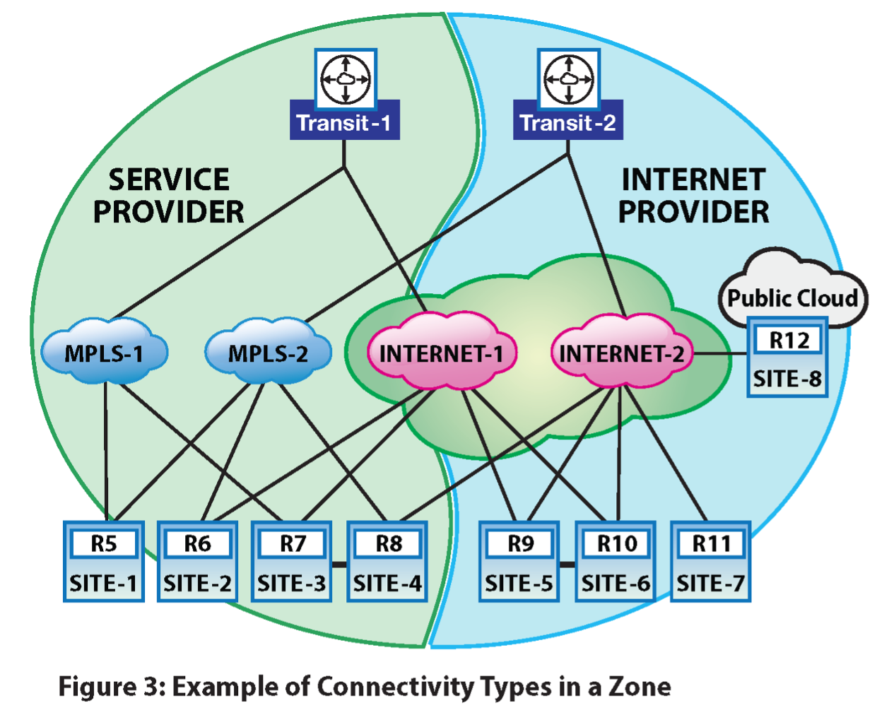
The network has sites connected by various SP networks. These SP networks map to specific path group names in EOS. So, if the path group name is the same, the routers can establish direct DPS paths over the SP network.
The earlier example shows two zones with 4 sites (1 hub and 3 spokes) in each zone. There are three path groups:
- MPLS-1
- MPLS-2
- Internet (doesn’t differentiate between Internet-1 and Internet-2 as they are connected)
The AVT feature breaks down the network into virtual topologies adapted using the best paths suitable for applications (traffic group). A virtual topology is influenced by:
- The application group (e.g., latency-sensitive, critical, etc.)
- The service that is needed (firewall, etc.)
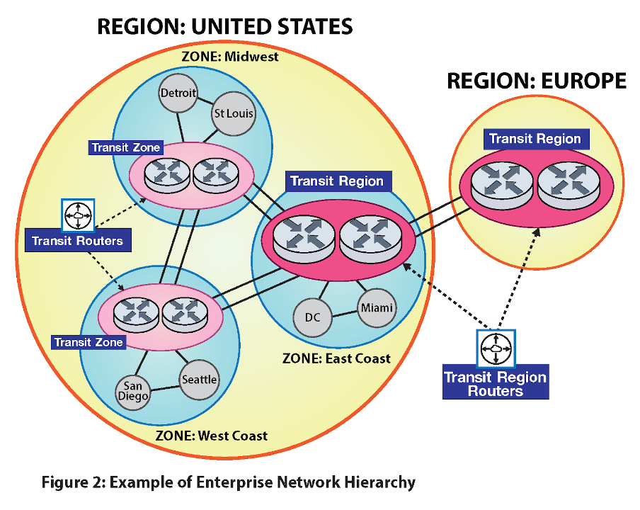
In the diagram earlier (Figure 2), AVT might select the MPLS-1 and the Internet path groups for traffic traversing from Branch-1 (R5) to Branch-3 (R7). AVT can choose the following paths:
- R5 -> R7 (direct path)
- R5-> H1 -> R7 (multi-hop path).
Auto-discovery and Creation of the Underlay Fabric
A BGP path selection exchanges the NLRI between all the routers in the network through the route reflectors, helping the routers auto-discover each other. Currently, every neighboring router exchanges advertisements, but the implementation may restrict the advertisements to only the concerned routers within a zone.
A BGP path-selection NLRI carries information about how to reach a router’s VTEP by advertising the router’s service provider (SP) routable IP address. The SP routable address can be a public IP address in the case of an ISP or a private IP address in the case of private networks, for example, based on MPLS. After routers auto-discover other peer routers and their corresponding WAN reachability information, they can establish tunnels with the peer routers over various underlying service provider networks. One can refer to this fabric of routers interconnected with tunnels as the underlay fabric or simply as the underlay.
BGP Link State
The AVT topology information and the traffic engineering metrics are sent from each router to the RR via BGP link state advertisements. Each WAN Routing System router sends its local node information and establishes DPS link information to the RR. The RR aggregates the node and the link information to build topologies for each AVT. For traffic engineering, each router periodically updates the RR about the latency, jitter, and loss rate measured for each DPS link. Currently, we have set the default timer for updates to 10 seconds. CloudVision Pathfinder uses the link measurements to calculate multi-hop DPS paths for each pair of nodes in the network.
BGP SR-TE
The multi-hop DPS paths calculated by CloudVision Pathfinder are distributed from the RR to every transit or edge router through traffic-engineered policies via BGP Segment Routing Traffic Engineering (SR-TE) updates. The WAN Routing System uses a new tunnel type, named DPS policy, to convey the multi-hop DPS path information.
CloudVision Pathfinder
The CloudVision Pathfinder software running on the RR receives a full view of the WAN network. Each router contributes BGP-LS updates to learn the topology view. The BGP RR receives the BGP-LS updates and passes on the node and link information to CloudVision Pathfinder. Each link also publishes a set of metrics.
CloudVision Pathfinder is responsible for computing paths from every source to every other destination in the WAN network. AVTs classify different types of traffic and require varying quality of service treatment in the WAN. Each AVT may have different constraints and objective functions to satisfy. The CloudVision Pathfinder software is responsible for computing the paths from different sources to every destination that satisfies the constraints and objective functions configured for each AVT.
A DPS tunnel between two routing nodes is composed of individual paths. The number of paths depends on the number of public WAN interfaces and their types. A source node can take any of those paths to reach an adjacent node. The individual paths have their metrics, and the router periodically updates each of these metrics.
The end-to-end paths computed by CloudVision Pathfinder are called multi-hop DPS paths. They consist of node router IDs and the individual paths between them. Each router receives traffic-engineered policies that express the multi-hop paths.
The multi-hop paths are then sent to each router through the RR using BGP SR-TE. Every node gets multi-hop paths to reach every destination in each AVT (i.e., a multi-hop path is specific to an AVT and satisfies the constraints and objective functions set forth by that AVT).
CloudVision Pathfinder includes the end-to-end metrics and multi-hop paths and sends periodic updates as metrics change.
CloudVision Pathfinder will recompute the routing table and distribute updates using BGP when reachability or metrics change.
AVT Configuration
Configure a Router Adaptive Virtual Topology
To simplify managing networking policies, divide the enterprise network hierarchically into regions, zones, sites, etc.
For example, an enterprise might have US, Europe, and Asia regions. Divide the US region further into East and West Coast (or states) zones. A zone comprises several sites: a branch, a campus, a data center, a point-of-presence (POP), or a cloud network. A site can have a few routers identified by their device number.
The full hierarchy is as follows:
- Region
- Zone
- Site
- Device
- BGP uses this configuration to configure all the parameters for the AVTs to work.
- Region ID must be unique across the customer network.
- Zone ID and site ID must be unique in the region.
router(config)#router adaptive-virtual-topology
router(config-adaptive-virtual-topology)#topology role <transit zone | edge | pathfinder>
router(config-adaptive-virtual-topology)#region <region name> id <region id>
router(config-adaptive-virtual-topology)#zone <zone name> id <zone id>
router(config-adaptive-virtual-topology)#site <site name> id <site id>
The role of a device could be edge, pathfinder, or transit connecting edge. The transit router, specified as a transit zone, could serve as a transit for nodes in zones within the same region.The transit router, specified as a transit region, could serve as a transit for nodes in different regions.
Branch and cloud routers are edge routers that don’t offer services and are configured as edge routers, whereas data center/campus edge routers are transit routers.
Define an AVT Profile
- Pathfinder-created paths are called multi-hop DPS paths. They consist of node router IDs and the individual paths between them. Traffic-engineered policies express the multi-hop paths and can be sent to each router.
- The multi-hop paths are then sent to each router through the RR using BGP SR-TE. Every node gets multi-hop paths to reach every destination in each AVT (i.e., a multi-hop path is specific to an AVT and satisfies the constraints and objective functions set forth by that AVT).
- Profiles are defined globally and applied to selected VRFs.
- Apply all the policies to the AVT profile. For example:
- Path Selection
- Internet Exit
- Make path selection definitions in the router path-selection command.
router(config-adaptive-virtual-topology)#profile <avt-name>
      !! feature configurations
router(config-profile-AVT)#path-selection load-balance <voice-lb>
- For example, a voice AVT profile is configured like so
router(config)#router adaptive-virtual-topology
router(config-adaptive-virtual-topology)#profile voice
router(config-profile-voice)#path-selection load-balance voice-load-balance
router(config-profile-voice)#
router(config)#router path-selection
router(config-dynamic-path-selection)#path-group mpls-group id 2
router(config-path-group-mpls-group-2)#local interface ethernet 2
router(config-mpls-group-interface-Ethernet2)#peer dynamic
router(config-peer-dynamic-mpls-group)#path-group internet-group id 3
router(config-path-group-internet-group-3)#local interface ethernet 3
router(config-internet-group-interface-Ethernet3)#peer dynamic
router(config-peer-dynamic-internet-group)#peer static router-ip 11.0.1.1
router(config-peer-router-ip-11.0.1.1-internet-group)#ipv4 address 10.0.3.1
router(config-peer-router-ip-11.0.1.1-internet-group)#
router(config)#router path-selection
router(config-dynamic-path-selection)#load-balance policy voice-load-balance
router(config-load-balance-policy-voice-load-balance)#latency 50
router(config-load-balance-policy-voice-load-balance)#path-group mpls-group
router(config-load-balance-policy-voice-load-balance)#path-group internet-group priority 2
router(config-load-balance-policy-voice-load-balance)#
The priority parameter selects a path if it meets the metrics; otherwise, the software will choose a path from the next priority. The path from the lower number in priority is chosen over paths from a higher number.
Define an AVT Policy
AVT policies can be used across VRFs as shown below:
router adaptive-virtual-topology
policy production
 	match application-profile <profile-name> [ <after | before> <profile-name> ]
		avt profile <avt-name>
                        dscp <value>
                        traffic-class <value>

match application-profile <profile-name>
	avt profile <avt-name>


                       ………...
match application-profile default
		avt profile <avt-name>
Application profile creation uses the deep packet inspection module.
Configuring a traffic class and DSCP values is available. If only a traffic class is configured for an AVT, the outer and inner DSCP values are rewritten based on the traffic-class-to-DSCP map configured if DSCP rewrite is enabled. If a DSCP value is configured for an AVT, the outer and inner DSCP values are rewritten based on the configured DSCP value if DSCP rewrite is enabled. The AVT ID and DSCP values used for the flow in one direction are also used for the reverse flow.
WAN Routing System’s AVT Sample Configuration:
router adaptive-virtual-topology
	profile voice
		load-balance voice-load-balance
	profile critical-data
		load-balance critical-data-load-balance
	profile default-avt
		load-balance default-load-balance
policy production
		match application-profile voice-app-profile
                		profile voice
                		dscp 62
                		tc 1
match application-profile critical-data-app-profile
		profile critical-data
match application-profile default
		profile default-avt
Also, note that DPS is applied to the default VRF in the WAN Routing System deployments for connectivity to CloudVision Pathfinder. The BGP session to CloudVision Pathfinder runs over a DPS session applied to the default VRF. For all other customer overlay VRFs DPS is applied to the AVTs.
Apply an AVT Policy
You can apply an AVT policy with the following command:
router adaptive-virtual-topology
         vrf <vrf>
                     policy <avt-policy-name>
                     profile <avt-name> avt-id <avt-id>
router adaptive-virtual-topology
vrf red
   avt policy production
   avt profile voice id 1
   avt profile critical-data id 2
   avt profile default-avt id 3
Control Plane AVT Configuration
An AVT policy classifies different application groups into the corresponding AVT and specifies what action profiles to apply on that AVT. The action profile selects different attributes for the traffic/flow classified into the AVT. For example, the action profile could select the type of load balancing across different links and the traffic class for the packets classified into the AVT. It can also set the internet-exit policy for flows belonging to the AVT that need to exit into the Internet.
profile control-plane
      path-selection load-balance control-plane-lb
   !
 policy defaultAvtPolicy
      match application-profile CONTROL_PLANE
         avt profile control-plane
      !
vrf default
      avt policy defaultAvtPolicy
      avt profile control-plane id 1
   !
Example Router Configuration
application traffic recognition
   application-profile Voice
      application CustomTaxApp
      application Whatsapp
   !
   application-profile CONTROL_PLANE
      application CONTROL_PLANE_APP
   !
   application ipv4 CustomTaxApp
      destination prefix field-set CustomTaxAppDstPrefixes
      protocol tcp destination port field-set CustomTaxAppDstPorts
   application ipv4 CONTROL_PLANE_APP
      destination prefix field-prefixes pfVtep
   !
   field-set ipv4 prefix CustomTaxAppDstPrefixes
      1.2.3.0/24 1.2.4.0/24
   !
   field-set ipv4 prefix pfVtep
      192.168.11.100/32
   !
   field-set l4-port CustomTaxAppDstPorts
      8800-8801
   !
router path-selection
            path-group mpls id 101
                local interface Ethernet2
                !
                peer dynamic
            !
load-balance policy control-plane-lb
      path-group Internet
      path-group MPLS
!
load-balance policy voice-lb
      latency 400
      jitter 80
      loss-rate 10.0
      path-group MPLS
      path-group Internet priority 2
!
router adaptive-virtual-topology
!! role is transit router
role transit

!! region is US
	region us   id    1

	!! zone id 2
	zone california id 2

	!! site is santa clara
	site santa-clara id 10

	!! Define all the AVT profiles
profile control-plane
      path-selection load-balance control-plane-lb
   !
   profile voice
      path-selection load-balance voice-lb
   !
   profile catch-all
      path-selection load-balance control-plane-lb
   !

	!! Define the AVT policy
   policy defaultAvtPolicy
      match application-profile CONTROL_PLANE
         avt profile control-plane
      !
      match application-profile Voice
         avt profile voice
      !
      match application-profile default
         avt profile catch-all
      !
   !
   policy officeAvtPolicy
      match application-profile Voice
         avt profile voice
      !
      match application-profile default
         avt profile control-plane
      !
   !

!! Apply the AVT policy on the VRF
   vrf default
      avt policy defaultAvtPolicy
      avt profile control-plane id 1
      avt profile voice id 2
      avt profile catch-all id 3
   !
   vrf office
      avt policy officeAvtPolicy
      avt profile control-plane id 1
      avt profile voice id 2
   !
Route Reflector AVT Configuration
The route reflector must be configured with all the AVT policies, including the one for load balancing for CloudVision Pathfinder to build all the topologies. This configuration is used purely to construct topologies on CloudVision Pathfinder and has no bearing on its data path.
router path-selection
	path-group mpls-group id 10
	!
	path-group internet-group id 20
	!
	load-balance policy voice-load-balance
   latency 50
   path-group mpls-group
   path-group internet-group priority 2
	load-balance policy critical-data-load-balance
   path-group mpls-group
   path-group internet-group priority 2
load-balance policy default-load-balance
   path-group internet-group

router adaptive-virtual-topology
!! role is pathfinder
role pathfinder

	!! Define all the AVT profiles
	profile voice
		path-selection load-balance voice-load-balance
	profile critical-data
		path-selection load-balance critical-data-load-balance
	profile default-avt
		path-selection load-balance default-load-balance

	!! Define the AVT policy
policy production
	           match application-profile voice-app-profile
                		avt profile voice
           match application-profile critical-data-app-profile
		           avt profile critical-data
           match application-profile default
		          avt profile default-avt

!! Apply the AVT policy on the VRF
vrf red
		avt policy production
	!! Create the AVTs in the VRFs
	avt profile voice id 1
	avt profile critical-data id 2
Border Gateway Protocol Link-State Configuration
BGP LS is used to convey the AVT topology and the DPS link metrics from the transit and the edge routers to the route reflector.
Enabling BGP LS to Import DPS on Routers
You can use the path-selection command on the transit and the edge routers to enable the import of the AVT node and DPS link information to BGP LS. The RR doesn’t need the path-selection command.
router bgp 1
   address-family link-state
      path-selection
Configuring a Role on the Route Reflector
The WAN Routing System router and the RR play different roles in BGP LS for processing the DPS information. You can use the following new command to specify the role:
router bgp 1
   address-family link-state
      path-selection role [ producer | consumer | propagator ]
In the producer role (default), the router advertises the imported AVT node and DPS link information using BGP LS advertisements. It discards all the BGP LS advertisements that were received. The software expects the transit and edge routers to operate in the producer role.
In the consumer role, the router accepts the received BGP LS advertisements and relays the received AVT node and DPS link information to CloudVision Pathfinder. The software expects the RR to operate in this role.
In the propagator role, the router re-advertises the received BGP LS advertisements to other BGP LS speakers. When multiple RRs are present, each RR should also operate in this role. The path-selection role consumer propagator command should be configured on all RRs.
Filtering Routes on a Route Reflector
The CloudVision Pathfinder software calculates multi-hop DPS paths between WAN Routing System network routers. Since a router only needs those paths, which are the headend, it is a big waste of control plane bandwidth if the RR sends all such paths to every router. Each DPS policy is attached with a route-target extended community to identify the headend router for ease of route filtering. BGP SR-TE automatically adds this route-target extended community parameter. This is the IPv4 address format route-target extended community, which contains the IPv4 address of the intended headend router for which this policy route is meant.
Adding an outbound route filtering configuration on the RR is recommended to send selective routes to each router. In particular, you should define a route map for each neighbor router to match the route-target extended community with the neighbor router’s VTEP address. Attach the route map to the corresponding neighbor’s outbound direction. Here’s an example of configuration:
ip extcommunity-list ngb1 permit rt 1.1.1.1:00
route-map rm1 permit 10
   match extcommunity ngb1
router bgp 100
   address-family ipv4 sr-te
      neighbor 1.1.1.1 activate
neighbor 1.1.1.1 route-map rm1 out
Segment Routing-Traffic Engineering Configuration
BGP SR-TE is used to convey calculated multi-hop DPS paths from the RR to all WAN Routing System routers in the network.
Enabling BGP SR-TE
Both the RR and the routers must enable the IPv4 SR-TE address family like so:
router bgp 1
   address-family ipv4 sr-te
      neighbor <NEIGHBOR> activate
This configuration enables the reception of both the regular SR policy and the new DPS policy tunnel types in the BGP SR-TE NLRI. The BGP SR-TE draft requires the SR policy tunnel type to be present in the message. Arista has relaxed this requirement for the WAN Routing System. A message containing either an SR or DPS policy is accepted upon reception.
This configuration also enables the transmission of the DPS policy tunnel type in the BGP SR-TE NLRI.
Filtering Routes on the Route Reflector
The RR aggregates all the AVT nodes and the DPS link information sent by the WAN Routing System routers and propagates it to other RRs. It does not need to propagate all the information back to the WAN Routing System routers. To save control plane bandwidth, we highly recommend configuring the following command on the RR to avoid sending BGP LS updates to the routers:
router bgp 65010
   address-family link-state
      neighbor EDGE missing-policy direction out action deny
Show Commands
AVT Flow Table
The show adaptive-virtual-topology flow command shows the path each flow takes in the overlay. Flows are displayed in both forward and reverse directions. Load balancing is done only in the forward direction, which shows valid AVT, interface, next-hop VTEP, and path ID. The reverse flow shows these fields as n/a because load balancing is unavailable. The Path Type: ID column identifies the path taken by the flow. Users can find the path information in the show adaptive-virtual-topology path output.
VRF     AVT      Source            Destination       Protocol Interface   Nexthop VTEP  Transit Path Type:ID
------- -------- ----------------- ----------------- -------- ----------- ------------- ------- -----------
vrf1    platinum 20.0.0.2:47803    20.0.1.2:56000    17       Ethernet3   11.0.3.1      no      multihop:1
vrf1    n/a      20.0.1.2:56000    20.0.0.2:47803    17       n/a         n/a           no      n/a
vrf1    platinum 20.0.0.2:47804    20.0.1.2:56000    17       Ethernet3   11.0.1.1      no      direct:2
vrf1    n/a      20.0.1.2:56000    20.0.0.2:47804    17       n/a         n/a           no      n/a
vrf1    platinum 20.0.0.2:47797    20.0.1.2:56000    17       Ethernet3   11.0.3.1      no      multihop:1
vrf1    n/a      20.0.1.2:56000    20.0.0.2:47797    17       n/a         n/a           no      n/a
default balance  11.0.0.1:179      11.0.2.1:45215    6        Ethernet5   11.0.2.1      no      direct:1
default n/a      11.0.2.1:45215    11.0.0.1:179      6        n/a         n/a           no      n/a
AVT Route Table
The show adaptive-virtual-topology path command displays direct and multi-hop paths for every valid VRF and AVT in the system. Users can filter the output by VRF, AVT, or destination.
A path becomes considered valid if it constitutes a direct or multi-hop path received from RR containing valid VRF and AVT information. A path is marked as active when it gets programmed to the platform. Each path receives identification through Path
Type: ID. The Destination column displays the end node to which overlay routes lead. The NextHop column indicates the initial hop in a path. The Hop List reveals the path labels within the hop stack, with the first path label appearing as the local DPS path name.
Router ID: 11.0.0.1
Role: edge
Region: us, Region ID: 1
Zone: texas, Zone ID: 101
Site: austin, Site ID: 1001

Code: * - valid, > - active, d - direct path, m - multihop path

VRF: vrf1, VNI: 100
AVT: platinum, AVT ID: 11
Application profile(s): default
    Path Type:ID  Destination   Nexthop VTEP  Priority   MTU  Latency   Jitter     Loss Hop List
    ------------- ------------- ------------- -------- ----- -------- -------- -------- ---------
*   direct:3      11.0.1.1      11.0.1.1             2  1464  3.497ms  1.140ms  0.0000% path3
*>  direct:2      11.0.1.1      11.0.1.1             1  1464  1.746ms  1.035ms  0.0000% path2
*>  multihop:1    11.0.1.1      11.0.3.1             1  1464  6.812ms  3.243ms  0.0000% path4,2
*   multihop:2    11.0.1.1      11.0.3.1             2  1464  5.756ms  3.464ms  0.0000% path4,5
*   multihop:3    11.0.1.1      11.0.3.1             2  1464  4.807ms  2.757ms  0.0000% path5,2
*   multihop:4    11.0.1.1      11.0.3.1             2  1464  3.751ms  2.978ms  0.0000% path5,5
*>  direct:4      11.0.3.1      11.0.3.1             1  1464  2.433ms  1.547ms  0.0000% path4
*   direct:5      11.0.3.1      11.0.3.1             2  1464  4.010ms  1.225ms  0.0000% path5

VRF: default (underlay)
AVT: balance, AVT ID: 10
Application profile(s): default
    Path Type:ID  Destination   Nexthop VTEP  Priority   MTU  Latency   Jitter     Loss Hop List
    ------------- ------------- ------------- -------- ----- -------- -------- -------- ---------
*>  direct:1      11.0.2.1      11.0.2.1             1  1464  3.613ms  6.471ms  0.0000% path1
AVT Routing Counters
The following AVT commands show packet/byte counters for egress traffic and display how the AVT flow distribution is working.
Showing AVT Counters
VRF  AVT    First Hop Path   Interfaces   Flows *     Bytes   Packets    Rate
—--  —----  —-------- —----- —---------   —------  —-------  —-------  —------
red  voice  11.0.1.1  path1  eth1          1000   23213123      5646    1 Gb/s
red  voice  11.0.1.1  path2  eth2           343    8938424       128    2 Mb/s
red  voice  11.0.1.1  path3  eth3         45645   32482348       245    9 Gb/s
red  voice  11.0.2.1  path5  eth1          1010   23214123      5746  500 Kb/s
red  voice  11.0.2.1  path7  eth2          3445    7938424       129    5 Mb/s
blue data   11.0.2.1  path5  eth1          1000    1232112      3322  2.5 Kb/s
blue data   11.0.2.1  path6  eth2           343     782342      1637   350 b/s
* Flows = Active Flows
Clearing AVT Counters
The clear adaptive-virtual-topology path counters command has no output. It flushes all counters to zero.
AVT and DPS Platform Counters
A set of counters is provided to check common mishaps happening in the data plane. The list includes, for instance, counters for packet drops, lookup failures, and missing flow cache:
- show platform sfe counters module AvtEgress
Name                             Owner       Counter Type Unit       Count
-------------------------------- ---------   ------------ ---------- -----
Avt-lookup-miss                  AvtEgress   module       packets    0
Avt-lookup-fail                  AvtEgress   module       packets    0
LbId-lookup-fail                 AvtEgress   module       packets    0
invalid-lbid                     AvtEgress   module       packets    0
no-Avt-FlowCache                 AvtEgress   module       packets    0
no-FlowCache                     AvtEgress   module       packets    0
no-Path                          AvtEgress   module       packets    0
AvtUtilPkt-Data                  AvtEgress   module       packets    0
AvtUtilPkt-Error                 AvtEgress   module       packets    0
Avt-Counter-lookup-fail          AvtEgress   module       packets    0
Avt-Counter-Memory-Allocations   AvtEgress   module       memoryBloc 0
Avt-Counter-Memory-Deallocations AvtEgress   module       memoryBloc 0
avt-fast-reroute                 AvtEgress   module       packets    0
avt-ingress-transit              AvtEgress   module       packets    0
avt-ingress-transitfib_bypass    AvtEgress   module       packets    0
- show platform sfe counters module dpsEgress
Name                             Owner       Counter Type Unit       Count
-------------------------------- ---------   ------------ ---------- -----
dpsEgress-Uninitialized          dpsEgress   module       packets    0
dpsEgress-No_Space               dpsEgress   module       packets    0
dpsEgress-VNI_Lookup_Fail        dpsEgress   module       packets    0
dpsEgress-Tun_Lookup_Fail        dpsEgress   module       packets    0
- show platform sfe counters module dps
Name                             Owner       Counter Type Unit       Count
-------------------------------- ---------   ------------ ---------- -----
LbId-lookup-fail                 dps         module       packets    0
invalid-lbid                     dps         module       packets    0
no-Dps-FlowCache                 dps         module       packets    0
no-FlowCache                     dps         module       packets    0
no-Path                          dps         module       packets    0
Failed-Frag                      dps         module       packets    0
Failed-Linearize                 dps         module       packets    0
Frag pkt counter                 dps         module       packets    0
Path Computation Engine Show Commands
Debugging on the Router
AVT can be debugged on each router using the show commands listed below.
Troubleshooting BGP
Normal BGP show commands can be used to debug BGP connections. The show bgp summary output displays BGP sessions established between a transit/edge router and the RR for the following address families: IPv4 SR-TE, IPv4 DPS, L2VPN EVPN, Link State:
#show bgp summary
BGP summary information for VRF default
Router identifier 0.0.0.1, local AS number 300
Neighbor          AS Session State AFI/SAFI                AFI/SAFI State   NLRI Rcd   NLRI Acc
-------- ----------- ------------- ----------------------- -------------- ---------- ----------
12.0.0.3         300 Established   IPv4 SR-TE              Negotiated             12         12
12.0.0.3         300 Established   IPv4 Dps                Negotiated             12         12
12.0.0.3         300 Established   L2VPN EVPN              Negotiated              8          8
12.0.0.3         300 Established   Link State Link State   Negotiated              0          0
# show bgp neighbors
BGP neighbor is 12.0.0.1, remote AS 300, internal link
  <snip>
  Additional-paths send mode:
    Dps: any
Troubleshooting BGP LS Content
The following commands can be used to verify an AVT node and the DPS link information conveyed through BGP LS:
show bgp link-state node [ detail ]
show bgp link-state link [ detail ]
# show bgp link-state node
BGP routing table information for VRF default
Router identifier 0.0.0.1, local AS number 300
BRIB status codes: * - valid, > - active, q - Queued for advertisement
NLRI codes: Proto - IGP Protocol
            I L1 - IS-IS Level-1, I L2 - IS-IS Level-2
            ID - Identifier (IGP Instance ID)
            RRID - Remote Node Router ID
            DPS - Dynamic Path Selection
        Type   Proto  ID    Router ID        NLRI Specific      Peer        Path
 * >    node   DPS    0     12.0.0.1         -                   -           -

# show bgp link-state node detail
BGP routing table information for VRF default
Router identifier 0.0.0.1, local AS number 300
BGP routing table entry for node: BGP DPS, Identifier: 0
Router ID: 12.0.0.1
 Paths: 1 available
  Local
    - from - (0.0.0.0)
      Origin IGP, metric -, localpref -, weight 0, received 01:01:09 ago, valid, local, best, imported (DPS)
      Role: edge
      Region ID: 1
      Zone ID: 101
      Site ID: 1001
      VNI: 200 AVT ID: 2
      VNI: 100 AVT ID: 2
      VNI: 100 AVT ID: 1
      VNI: 200 AVT ID: 1
      Flags: []
# show bgp link-state link
BGP routing table information for VRF default
Router identifier 0.0.0.1, local AS number 300
BRIB status codes: * - valid, > - active, q - Queued for advertisement
NLRI codes: Proto - IGP Protocol
            I L1 - IS-IS Level-1, I L2 - IS-IS Level-2
            ID - Identifier (IGP Instance ID)
            RRID - Remote Node Router ID
            DPS - Dynamic Path Selection
        Type   Proto  ID    Router ID        NLRI Specific              Peer    Path
 * >    link   DPS    0     12.0.0.1         RRID: 12.0.0.2              -       -
                                             WAN ID: Local 1 Remote 1
                                             WAN Group ID: Local 100
 * >    link   DPS    0     12.0.0.1         RRID: 12.0.0.2              -       -
                                             WAN ID: Local 2 Remote 2
                                             WAN Group ID: Local 101

# show bgp link-state link detail
BGP routing table information for VRF default
Router identifier 0.0.0.1, local AS number 300
BGP routing table entry for link: BGP DPS, Identifier: 0
Local node router ID: 12.0.0.1, Remote node router ID: 12.0.0.2
 Paths: 1 available
  Local
    - from - (0.0.0.0)
      Origin IGP, metric -, localpref -, weight 0, received 01:09:43 ago, valid, local, best, imported (DPS)
      IGP metric: 0
      Segment label: 5
      Path MTU: 1464
      Path latency: 24049
      Path jitter: 1843
BGP routing table entry for link: BGP DPS, Identifier: 0
Local node router ID: 12.0.0.1, Remote node router ID: 12.0.0.2
 Paths: 1 available
  Local
    - from - (0.0.0.0)
      Origin IGP, metric -, localpref -, weight 0, received 01:09:43 ago, valid, local, best, imported (DPS)
      IGP metric: 0
      Segment label: 6
      Path MTU: 1464
      Path latency: 24030
      Path jitter: 1862
Troubleshooting BGP SR-TE Content
The existing show bgp sr-te command allows for an overview of all SR-TE routes, encompassing both the regular SR policy and the new DPS policy. To discern the tunnel type a route carries, reference the Color and Distinguisher columns. If a route carries a DPS policy, the Color column indicates which VRF and AVT this route belongs to in the <VRF name>:<AVT name> format. The Distinguisher column displays the source router ID in IPv4 address format.
#show bgp sr-te
BGP routing table information for VRF default
Router identifier 0.0.0.1, local AS number 300
Route status codes: s - suppressed, * - valid, > - active, # - not installed, E - ECMP head, e - ECMP
                    S - Stale, c - Contributing to ECMP, b - backup, L - labeled-unicast
                    % - Pending BGP convergence
Origin codes: i - IGP, e - EGP, ? - incomplete
AS Path Attributes: Or-ID - Originator ID, C-LST - Cluster List, LL Nexthop - Link Local Nexthop
        Endpoint      Color         Distinguisher Next Hop        Metric  LocPref Weight  Path
 * >    12.0.0.2      eng:voiceAvt  12.0.0.1      12.0.0.3        -       100     0       i
 * >    12.0.0.2      eng:dataAvt   12.0.0.1      12.0.0.3        -       100     0       i

#show bgp sr-te detail
BGP routing table information for VRF default
Router identifier 0.0.0.1, local AS number 300
BGP routing table entry for Endpoint: 12.0.0.2, VNI: 100, VRF: eng, AVT: voiceAvt (1), Router: 12.0.0.1
 Paths: 1 available
  Local
    12.0.0.3 from 12.0.0.3 (0.0.0.3)
      Origin IGP, metric -, localpref 100, weight 0, received 00:00:16 ago, valid, internal, best
      Extended Community: Route-Target-IP:12.0.0.1:0
      Rx SAFI: SR TE Policy
      Tunnel encapsulation attribute: DPS policy
         Preference: 100
         Segment List: Label Stack: [9 8], latency: 51.423 msec, jitter: 4.083 msec, MTU: 1464 bytes, priority: 1
         Segment List: Label Stack: [7 5], latency: 51.771 msec, jitter: 3.974 msec, MTU: 1464 bytes, priority: 1
         Segment List: Label Stack: [9 5 5], latency: 75.948 msec, jitter: 6.885 msec, MTU: 1464 bytes, priority: 1
BGP routing table entry for Endpoint: 12.0.0.2, VNI: 100, VRF: eng, AVT: dataAvt (2), Router: 12.0.0.1
 Paths: 1 available
  Local
    12.0.0.3 from 12.0.0.3 (0.0.0.3)
      Origin IGP, metric -, localpref 100, weight 0, received 00:00:16 ago, valid, internal, best
      Extended Community: Route-Target-IP:12.0.0.1:0
      Rx SAFI: SR TE Policy
      Tunnel encapsulation attribute: DPS policy
         Preference: 100
         Segment List: Label Stack: [10 9], latency: 51.584 msec, jitter: 4.137 msec, MTU: 1464 bytes, priority: 1
         Segment List: Label Stack: [8 6], latency: 51.912 msec, jitter: 4.047 msec, MTU: 1464 bytes, priority: 1
         Segment List: Label Stack: [10 6 6], latency: 75.817 msec, jitter: 6.781 msec, MTU: 1464 bytes, priority: 1
#show bgp sr-te endpoint <endpoint> path-selection color-vrf <avt vrf name> avt <avt name> [router <source router IP>] [detail]
path-selection keyword in this command indicates that it is the DPS policy, rather than the regular SR policy, for the specified endpoint. This command output contains only one entry:
#show bgp sr-te endpoint 12.0.0.2 path-selection color-vrf eng avt dataAvt router 12.0.0.1
BGP routing table information for VRF default
Router identifier 0.0.0.1, local AS number 300
BGP routing table entry for Endpoint: 12.0.0.2, VNI: 100, VRF: eng, AVT: dataAvt (2), Router: 12.0.0.1
 Paths: 2 available
  Local
    12.0.0.3 from 12.0.0.3 (0.0.0.3)
      Origin IGP, metric -, localpref 100, weight 0, received 00:00:27 ago, valid, internal, best
      Extended Community: Route-Target-IP:12.0.0.1:0
      Rx SAFI: SR TE Policy
This command also offers a detail keyword to display more information. Its format is the same as the show bgp sr-te [detail] command.
show bgp neighbors <neighbor_address> [ ipv4 | ipv6 ] sr-te ( policies | received-policies | advertised-policies ) [ detail ]
Debug BGP Path-Selection Content
BGP path selection is used to convey information among WAN Routing System routers for dynamic DPS tunnel establishment. The following command can be used to verify the tunnel information.
show bgp path-selection [detail]
#show bgp path-selection
BGP routing table information for VRF default
Router identifier 0.0.0.1, local AS number 300
Route status code: * - valid, S - Stale, q - Queued for advertisement

    NLRI      VTEP           Endpoint        Path Group    WAN ID  UDP Port
 *  ipv4Dps   12.0.0.1/32    10.1.1.1        MPLS               1      4793
 *  ipv4Ipsec 12.0.0.1/32    -               -                  -         -

#show bgp path-selection detail
BGP routing table information for VRF default
Router identifier 0.0.0.1, local AS number 300
Bgp routing table entry for ipv4Dps VTEP 12.0.0.3/32
 Paths: 1 available
  Local
    - from - (0.0.0.0)
      Origin IGP, metric -, localpref -, weight 0, received 00:01:57 ago, valid, local
      Tunnel encapsulation attribute: Dynamic path selection
        Endpoint: 10.0.0.1, Path group name: internet, WAN ID: 1, UDP port: 4793
      Extended community: route target
        Role: edge, region ID: 1, zone ID: 101, site ID: 1001
Bgp routing table entry for ipv4Ipsec VTEP 12.0.0.3/32
 Paths: 1 available
  Local
    - from - (0.0.0.0)
      Origin IGP, metric -, localpref -, weight 0, received 00:00:01 ago, valid, internal
      Tunnel encapsulation attribute: IP security
        Initial contact: true, Rekey counter: 1010101010, Nonce length: 25
        DH group: 1, DH key length: 18
        Encryption algo: aes128, Authentication algo: sha1
AVT Commands
router adaptive-virtual-topology
The router adaptive-virtual-topology command is used by BGP to define the region, zone, role, and site parameters. Note, all the parameters need to be configured for AVTs.
The no router adaptive-virtual-topology and default router adaptive-virtual-topology commands disable router adaptive-virtual-topology from the specified domain by removing the corresponding router adaptive-virtual-topology command from running-config.
Command Mode
Global Configuration
Command Syntax
router adaptive-virtual-topology
no router adaptive-virtual-topology
default router adaptive-virtual-topology
- policy: Configure policy name.
- profile: Configure AVT name.
- region: Configure region name. The region ID must be unique across the customer network.
- site: Configure site name.
- topology: Configure role name.
- vrf: Configure VRF name.
- zone: Configure zone name. The zone ID and site ID must be unique in the region.
Example
router adaptive-virtual-topology
!! role is transit router
role transit

!! region is US
	region us   id    1

	!! zone id 2
	zone california id 2

	!! site is santa clara
	site santa-clara id 10

	!! Define all the AVT profiles
profile control-plane
      path-selection load-balance control-plane-lb
   !
   profile voice
      path-selection load-balance voice-lb
   !
   profile catch-all
      path-selection load-balance control-plane-lb
   !

	!! Define the AVT policy
   policy defaultAvtPolicy
      match application-profile CONTROL_PLANE
         avt profile control-plane
      !
      match application-profile Voice
         avt profile voice
      !
      match application-profile default
         avt profile catch-all
      !
   !
   policy officeAvtPolicy
      match application-profile Voice
         avt profile voice
      !
      match application-profile default
         avt profile control-plane
      !
   !

!! Apply the AVT policy on the VRF
   vrf default
      avt policy defaultAvtPolicy
      avt profile control-plane id 1
      avt profile voice id 2
      avt profile catch-all id 3
   !
   vrf office
      avt policy officeAvtPolicy
      avt profile control-plane id 1
      avt profile voice id 2
   !
show traffic-engineering adaptive-virtual-topology database
The show traffic-engineering adaptive-virtual-topology database command displays the database of routers and their interconnections.
Command Mode
EXEC
Command Syntax
show traffic-engineering adaptive-virtual-topology database
- This command displays multi-hop path information between two nodes. For each such multi-hop path its individual DPS path labels are specified along with the VTEP endpoint for the DPS path and the metrics for the DPS path.
switch# show traffic-engineering adaptive-virtual-topology database
Node: 12.0.0.1
Region ID: 1
Zone ID: 101
Site ID: 1011
Role: edge
AVT:  6553602 6553601
Adjacency 12.0.0.4
Label: 2
   Local WAN ID: 3354128354, Peer WAN ID: 2, Path Group ID: 101
   Latency: 22.011999 msec, Jitter: 0.977000 msec, Loss: 0.000000%
   Path MTU: 1464
Adjacency 12.0.0.2
Label: 4
   Local WAN ID: 3354128354, Peer WAN ID: 2, Path Group ID: 101
   Latency: 22.011999 msec, Jitter: 0.977000 msec, Loss: 0.000000%
   Path MTU: 1464
Adjacency 12.0.0.5
Label: 3
   Local WAN ID: 3354128354, Peer WAN ID: 2, Path Group ID: 101
   Latency: 22.011999 msec, Jitter: 0.977000 msec, Loss: 0.000000%
   Path MTU: 1464
show traffic-engineering adaptive-virtual-topology paths
The show traffic-engineering adaptive-virtual-topology paths command displays the traffic engineered paths.
Command Mode
EXEC
Command Syntax
show traffic-engineering adaptive-virtual-topology paths [ source <router ID> vrf <vrf name> avt <avt name> destination <router ID>]
Parameters
- source <router ID> specifies the source router ID.
- vrf <vrf name> specifies the VRF name.
- avt <avt name> specifies the AVT name.
- destination <router ID> specifies the destination router ID.
- This command displays all the best multi-hop paths between a source and a destination for a given VRF and AVT.
switch# show traffic-engineering adaptive-virtual-topology paths [ ( source <12.0.0.2> ) ( vrf <eng> )( avt <voiceAvt> ) ( destination <12.0.0.5> ) ]
Code: # - Path discovered, < - Path accepted in AVT, * - Path advertised to edge

Src: 12.0.0.2, Dst: 12.0.0.5
VRF: eng, VNI: 100
Avt: voiceAvt, Avt ID: 1
   Path First hop        Priority  MTU  Latency   Jitter     Loss Labels
   ---- ---------------- -------- ---- -------- -------- -------- --------------------------------
#<*   1 12.0.0.4                1 1464 46.822ms  9.200ms   0.000% 2,4
show adaptive-virtual-topology path
The show adaptive-virtual-topology path command displays direct and multi-hop paths for every valid VRF and AVT in the system.
Command Mode
EXEC
Command Syntax
show adaptive-virtual-topology path [ vrf<vrf name> |avt <avt name> |destination <dst IP> ]
Parameter
- vrf <vrf name> specifies VRF instances name.
- avt <avt name> specifies AVT name.
- destination <dst IP> specifies destination IP.
- This command displays direct and multi-hop paths for every valid VRF and AVT in the system.
switch# show adaptive-virtual-topology path
Router ID: 11.0.0.1
Role: edge
Region: us, Region ID: 1
Zone: texas, Zone ID: 101
Site: austin, Site ID: 1001

Code: * - valid, > - active, d - direct path, m - multihop path

VRF: vrf1, VNI: 100
AVT: platinum, AVT ID: 11
Application profile(s): default
    Path Type:ID  Destination   Nexthop VTEP  Priority   MTU  Latency   Jitter     Loss Hop List
    ------------- ------------- ------------- -------- ----- -------- -------- -------- ---------
*   direct:3      11.0.1.1      11.0.1.1             2  1464  3.497ms  1.140ms  0.0000% path3
*>  direct:2      11.0.1.1      11.0.1.1             1  1464  1.746ms  1.035ms  0.0000% path2
*>  multihop:1    11.0.1.1      11.0.3.1             1  1464  6.812ms  3.243ms  0.0000% path4,2
*   multihop:2    11.0.1.1      11.0.3.1             2  1464  5.756ms  3.464ms  0.0000% path4,5
*   multihop:3    11.0.1.1      11.0.3.1             2  1464  4.807ms  2.757ms  0.0000% path5,2
*   multihop:4    11.0.1.1      11.0.3.1             2  1464  3.751ms  2.978ms  0.0000% path5,5
*>  direct:4      11.0.3.1      11.0.3.1             1  1464  2.433ms  1.547ms  0.0000% path4
*   direct:5      11.0.3.1      11.0.3.1             2  1464  4.010ms  1.225ms  0.0000% path5

VRF: default (underlay)
AVT: balance, AVT ID: 10
Application profile(s): default
    Path Type:ID  Destination   Nexthop VTEP  Priority   MTU  Latency   Jitter     Loss Hop List
    ------------- ------------- ------------- -------- ----- -------- -------- -------- ---------
*>  direct:1      11.0.2.1      11.0.2.1             1  1464  3.613ms  6.471ms  0.0000% path1
show adaptive-virtual-topology flow
The show adaptive-virtual-topology flow command displays the path taken by each flow in the overlay.
Command Mode
EXEC
Command Syntax
show adaptive-virtual-topology flow [vrf <vrf name> | avt <avt name> | src-ip <src-IP> | src-port <src-port> | dst-ip <dst-IP> | dst-port <dst-port>]
- vrf <vrf name>: specifies the VRF name.
- avt <avt name>: specifies the AVT name.
- src-ip <src-IP>: specifies the Source IP.
- src-port <src-port>: specifies the Source Port.
- dst-ip <dst-IP>: specifies the Destination IP.
- dst-port <dst-port>: specifies the Destination Port.
- This command shows the path taken by each flow in the overlay. Flows are displayed in both forward and reverse directions.
switch# show adaptive-virtual-topology flow
VRF     AVT      Source            Destination       Protocol Interface   Nexthop VTEP  Transit Path Type:ID
------- -------- ----------------- ----------------- -------- ----------- ------------- ------- -----------
vrf1    platinum 20.0.0.2:47803    20.0.1.2:56000    17       Ethernet3   11.0.3.1      no      multihop:1
vrf1    n/a      20.0.1.2:56000    20.0.0.2:47803    17       n/a         n/a           no      n/a
vrf1    platinum 20.0.0.2:47804    20.0.1.2:56000    17       Ethernet3   11.0.1.1      no      direct:2
vrf1    n/a      20.0.1.2:56000    20.0.0.2:47804    17       n/a         n/a           no      n/a
vrf1    platinum 20.0.0.2:47797    20.0.1.2:56000    17       Ethernet3   11.0.3.1      no      multihop:1
vrf1    n/a      20.0.1.2:56000    20.0.0.2:47797    17       n/a         n/a           no      n/a
default balance  11.0.0.1:179      11.0.2.1:45215    6        Ethernet5   11.0.2.1      no      direct:1
default n/a      11.0.2.1:45215    11.0.0.1:179      6        n/a         n/a           no      n/a
show platform sfe counters module
The show platform sfe counters module command displays the list of counters for packet drops, lookup failures, and missing flow cache.
Command Mode
EXEC
Command Syntax
show platform sfe counters module
- This command displays information about the AVT Egress data.
switch# show platform sfe counters module AvtEgress
Name                             Owner       Counter Type Unit       Count
-------------------------------- ---------   ------------ ---------- -----
Avt-lookup-miss                  AvtEgress   module       packets    0
Avt-lookup-fail                  AvtEgress   module       packets    0
LbId-lookup-fail                 AvtEgress   module       packets    0
invalid-lbid                     AvtEgress   module       packets    0
no-Avt-FlowCache                 AvtEgress   module       packets    0
no-FlowCache                     AvtEgress   module       packets    0
no-Path                          AvtEgress   module       packets    0
AvtUtilPkt-Data                  AvtEgress   module       packets    0
AvtUtilPkt-Error                 AvtEgress   module       packets    0
Avt-Counter-lookup-fail          AvtEgress   module       packets    0
Avt-Counter-Memory-Allocations   AvtEgress   module       memoryBloc 0
Avt-Counter-Memory-Deallocations AvtEgress   module       memoryBloc 0
avt-fast-reroute                 AvtEgress   module       packets    0
avt-ingress-transit              AvtEgress   module       packets    0
avt-ingress-transitfib_bypass    AvtEgress   module       packets    0
- This command displays information about the DPS Egress data.
switch# show platform sfe counters module dpsEgress
Name                             Owner       Counter Type Unit       Count
-------------------------------- ---------   ------------ ---------- -----
dpsEgress-Uninitialized          dpsEgress   module       packets    0
dpsEgress-No_Space               dpsEgress   module       packets    0
dpsEgress-VNI_Lookup_Fail        dpsEgress   module       packets    0
dpsEgress-Tun_Lookup_Fail        dpsEgress   module       packets    0
- This command displays information about the DPS data.
switch# show platform sfe counters module dps
Name                             Owner       Counter Type Unit       Count
-------------------------------- ---------   ------------ ---------- -----
LbId-lookup-fail                 dps         module       packets    0
invalid-lbid                     dps         module       packets    0
no-Dps-FlowCache                 dps         module       packets    0
no-FlowCache                     dps         module       packets    0
no-Path                          dps         module       packets    0
Failed-Frag                      dps         module       packets    0
Failed-Linearize                 dps         module       packets    0
Frag pkt counter                 dps         module       packets    0
show adaptive-virtual-topology path counters
The show adaptive-virtual-topology path counters command displays the counter details for every (VRF, AVT, first-hop path) parameter tuple.
Command Mode
EXEC
Command Syntax
show adaptive-virtual-topology path [ vrf <vrf name> | avt <avt name> | hop <first-hop-ip> | path <path-id> ]
Parameter
- vrf <vrf name> specifies VRF instances name.
- avt <avt name> specifies AVT name.
- destination <dst IP> specifies destination IP.
- hop <first-hop-ip> specifies the first hop IP.
- path <path-id> specifies the path ID.
- This command displays the counter details for every (VRF, AVT, first-hop path) parameter tuple.
switch# show adaptive-virtual-topology path counters
VRF  AVT    First Hop Path   Interfaces   Flows *     Bytes   Packets    Rate
—--  —----  —-------- —----- —---------   —------  —-------  —-------  —------
red  voice  11.0.1.1  path1  eth1          1000   23213123      5646    1 Gb/s
red  voice  11.0.1.1  path2  eth2           343    8938424       128    2 Mb/s
red  voice  11.0.1.1  path3  eth3         45645   32482348       245    9 Gb/s
red  voice  11.0.2.1  path5  eth1          1010   23214123      5746  500 Kb/s
red  voice  11.0.2.1  path7  eth2          3445    7938424       129    5 Mb/s
blue data   11.0.2.1  path5  eth1          1000    1232112      3322  2.5 Kb/s
blue data   11.0.2.1  path6  eth2           343     782342      1637   350 b/s
* Flows = Active Flows
clear adaptive-virtual-topology path counters
The clear adaptive-virtual-topology path counters command flushes all counters to zero.
Command Mode
EXEC
Command Syntax
clear adaptive-virtual-topology path counters