Cabling the Switch
Grounding the Switch
After mounting the switch into the rack, this section discusses how to connect the switch to the data center ground.
Figure 1 - Earth Grounding Pad Sockets for Models without Management Ports on the Rear Panel display the grounding pads on the rear panel's bottom corners for the models with no management ports on the rear panel.
Figure 2 - Earth Grounding Pad Sockets for Models with Management Ports on the Rear Panel display the location of the grounding pads on the rear panel for models with management ports on the rear panel. There are threaded holes under the sticker on the right (next to PS2) that warn about “1 min”.
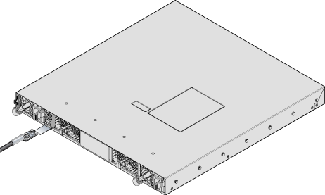
Figure 3 - Earth Grounding Adapter for DCS-7050SX3-48YC8 displays the location of the grounding assembly on the rear panel for DCS-7050SX3-48YC8.
Grounding wires and grounding lugs (M4 x 0.7) are not supplied. Wire size should meet local and national installation requirements. Commercially available 6 AWG wire is recommended for installations in the U.S.
À la terre et de mise à la terre fils cosses (M4 x 0.7) ne sont pas fournis. Calibre des fils doit satisfaire des exigences de l’installation locale et nationale. Disponible dans le commerce 6 fils AWG est recommandé pour les installations aux États-Unis.
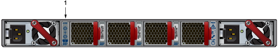
| 1 | Earth grounding pad |
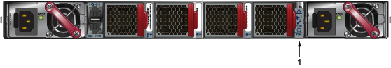
| 1 | Earth grounding pad |
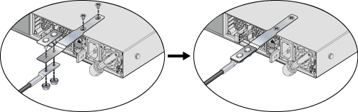
Grounding Adapter Assembly (DCS-7050SX3-48YC8)
Use the following steps to assemble and attach a grounding assembly to the chassis before mounting it into the rack.
Figure 4 - Earth Grounding Adapter Assembly for DCS-7050SX3-48YC8 shows the exploded and assembled views.
The following switches support external chassis grounding. Identify the location for attaching the adapter or the lug. As shown in the example, the attachment point is on the bottom of the chassis for the switches that support the KIT-GND-EXT-1RU grounding kit.
| Switch | Grounding Kit Adapter |
|---|---|
| DCS-7050QX-32S | Attach ground directly to back |
| DCS-7050TX-64 | Attach ground directly to back |
| DCS-7050SX-72 | |
| DCS-7050TX-96 | |
| DCS-7050CX3-32S | Attach ground directly to back |
| DCS-7050CX3M-32S | Attach ground directly to back |
| DCS-7050SX3-24YC4C-S | KIT-GND-EXT-1RU |
| DCS-7050TX-48 | Attach ground directly to back |
| DCS-7050SX-64 | Attach ground directly to back |
| DCS-7050TX-72Q | Attach ground directly to back |
| DCS-7050SX2-72Q | Attach ground directly to back |
| DCS-7050SX3-48YC12 | Attach ground directly to back |
| DCS-7050TX3-48C8 | KIT-GND-EXT-1RU |
| DCS-7050SX3-48YC8C | KIT-GND-EXT-1RU |
| DCS-7050QX2-32S | Attach ground directly to back |
| DCS-7050TX-72 | Attach ground directly to back |
| DCS-7050SX-72Q | |
| DCS-7050SX-96 | |
| DCS-7050SX3-48YC8 | KIT-GND-EXT-1RU |
| DCS-7050SX3-48C8 | KIT-GND-EXT-1RU |
Connecting Power Cables
This section discusses the correct procedure for connecting the power cables to the device.
Installation of this equipment must comply with local and national electrical codes. Consult with the appropriate regulatory agencies and inspection authorities to ensure compliance if necessary.
L'installation de cet équipement doit être conforme aux codes électriques locaux et nationaux. Consultez les agences de réglementation et les autorités d'inspection appropriées pour garantir la conformité si nécessaire.
The switch operates with two installed power supplies. At least one power supply must connect to a power source. Two circuits provide redundancy protection. The Rear Panel displays the location of the power supplies on the rear panel of the switch.
Read all installation instructions before connecting the system to the power source.
Lire toutes les instructions d’installation avant de brancher le système à la source d’alimentation.
- Non-Redundant Configuration:Connect power to either of the two power supplies.
- Redundant Power Supply Configuration:Connect power to both power supplies.
- Power down the Switch: Remove all power cords and wires from the power supplies.
Important:
This equipment must be grounded. Never defeat the ground conductor.
Cet équipement doit être mis à la terre. Ne jamais modifier le conducteur de terre.
Important:This unit requires overcurrent protection.
Cet appareil requiert une protection contre les surintensités.
AC Power Supplies
- PWR-500AC
- PWR-511-AC
- PWR-1011-AC-RED
Note: The handle color indicates the airflow direction for all PSUs.
The Figure 5 - PWR-500AC AC Power Supply displays the PWR-500AC AC power supply, including the power socket on the left side of the module. The AC power supply connects to a circuit providing the required power, as Table 4 - Switch Specifications (Power Draw) specified.
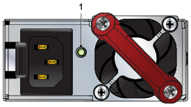
| 1 | Power supply status LED |
The Figure 6 - PWR-1011-AC-RED AC Power Supply displays the PWR-1011-AC-RED AC power supply, including the power socket on the right side of the module. The AC power supply connects to a circuit providing the required power, as Table 4 - Switch Specifications (Power Draw) specified.
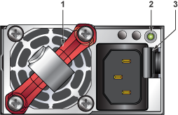
| 1 | Handle | 2 | Power supply status LED | 3 | Release |
The power supplies require power cables that comply with IEC-320. The accessory kit provides two IEC-320-compliant power cables with appropriate connectors for the PSUs.
DC Power Supplies
- PWR-500-DC
- PWR-511-DC
- PWR-1011-DC-RED
Note: The handle color indicates the airflow direction for all PSUs.
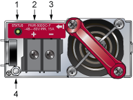
| 1 | Power supply status LED | 3 | Battery Return |
| 2 | -48V | 4 | Protective Earth |
The Figure 8 - PWR-1011-DC DC Power Supplies displays the PWR-1011-DC DC power supply.
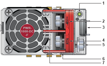
| 1 | Power supply status LED | 4 | Battery Return | 7 | Terminal cover |
| 2 | -48V | 5 | Protective Earth | ||
| 3 | Release | 6 | Handle |
A disconnect device must be provided as part of the installation.
Un dispositif de sectionnement doit être fourni dans le cadre de l'installation.
Ensure power is removed from DC circuits before performing any installation actions. Locate the disconnect device, circuit breakers, or fuses on DC power lines servicing the circuits. Turn off the power line circuits or remove the fuses.
Pouvoir assurer qu'il est retiré de circuits DC avant d'effectuer des actions d'installation . Localiser les disjoncteurs ou des fusibles sur les lignes de courant continu desservant les circuits. Coupez les circuits de lignes d'alimentation ou retirer les fusibles.
Wire size must comply with local and national requirements and electrical codes. Use only copper wire.
Le calibre du fil doit être conforme aux exigences locales et nationales et les codes électriques. Utiliser du fil de cuivre.
Apply ground connection to the switch during installation and remove last when removing power.
Appliquez une connexion à la terre au commutateur pendant l'installation et retirez-la en dernier lors de la mise hors tension.
Connecting the DC Power Supply
Wire and Lug Preparation
Before installing, remove power from DC circuits by turning off the power line servicing the circuits. Prepare the stranded wiring before you begin a DC power installation.
Connecting a DC Power Supply to a Power Source
To connect a DC power supply to a power source:
Ensure power is removed from DC circuits before performing any installation actions. Locate circuit breakers or fuses on DC power lines servicing the circuits. Turn off the power line circuits or remove the fuses.
Assurez-vous de pouvoir retirer des circuits en courant continu avant d’effectuer toute action d’installation.Localiser les disjoncteurs ou fusibles sur les lignes électriques DC entretien des circuits. Mettez hors tension le circuit ligne ou retirer les fusibles.
Wire size must comply with local and national requirements and electrical codes. Use only copper wire.
Calibre doit respecter les exigences locales et nationales et les codes de l’électricité. Utiliser seulement du fil de cuivre.
Apply the ground connection first during installation and remove it last when removing power.
Appliquez d'abord la connexion à la terre lors de l'installation et retirez-la en dernier lors de la mise hors tension.
Connecting Serial and Management Cables
This section discusses the serial and management cable requirements and connections.
- RJ-45 to DB-9 serial adapter cable.
- RJ-45 Ethernet cable.
The front or rear panels have the console, management, and USB ports.
Table 3 - RJ-45 to DB-9 Connections lists the pin connections of the RJ-45 to DB-9 adapter cable.
| RJ-45 | DB-9 | RJ-45 | DB-9 | |||||
|---|---|---|---|---|---|---|---|---|
| RTS | 1 | 8 | CTS | GND | 5 | 5 | GND | |
| DTR | 2 | 6 | DSR | RXD | 6 | 3 | TXD | |
| TXD | 3 | 2 | RXD | DSR | 7 | 4 | DTR | |
| GND | 4 | 5 | GND | CTS | 8 | 7 | RTS | |
Figure 9 - Console, Management, and USB Ports display the console, management, and USB ports in a representative configuration. Some earlier devices had ports where the USB port was located slightly differently.
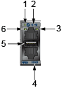
| 1 | System status LED | 3 | Activity status LED | 5 | USB port |
| 2 | Ethernet management port | 4 | Serial console port | 6 | Link status LED |
-
Console (Serial) Port: Connect to a PC with the RJ-45 to DB-9 serial adapter cable. The switch uses the following default settings:
- 9600 baud
- No flow control
- 1 stop bit
- No parity bits
- 8 data bits
- Ethernet Management Port: Connect to 10/100/1000 management network with RJ-45 Ethernet cable.
- USB Port: The USB port may be used for software or configuration updates.
CAUTION:
Excessive bending can damage interface cables, especially optical cables.
Flexion excessive peut endommager les câbles d’interface, notamment des câbles optiques.