Rack Installation
Use the following steps to assemble the racking rails and attaching the components to the system.
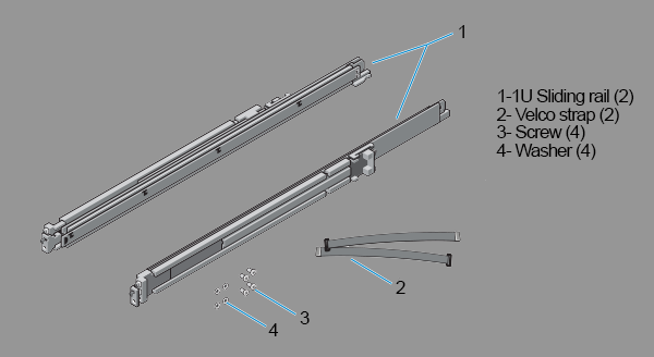
- Identifying the Rail Kit Contents.
Locate the components for installing the rail kit assembly:
-
Two sliding rail assemblies (1).
-
Two hook and loop straps (2).
-
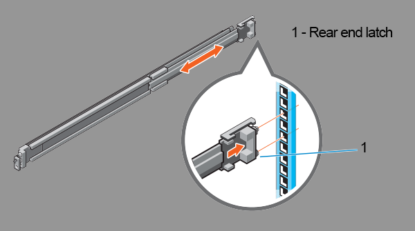
- Installing and Removing Tool-less Rails (Square Hole or Round Hole Racks).
- Position the left and right rail end pieces labeled FRONT facing inward and orient each end piece to seat in the holes on the front side of the vertical rack flanges (1).
- Align each end piece in the bottom and top holes of the desired U spaces (2).
- Engage the back end of the rail until it fully seats on the vertical rack flange and the latch clicks into place. Repeat these steps to position and seat the front end piece on the vertical rack flange (3).
- To remove the rails, pull the latch release button on the end piece midpoint and unseat each rail (4).
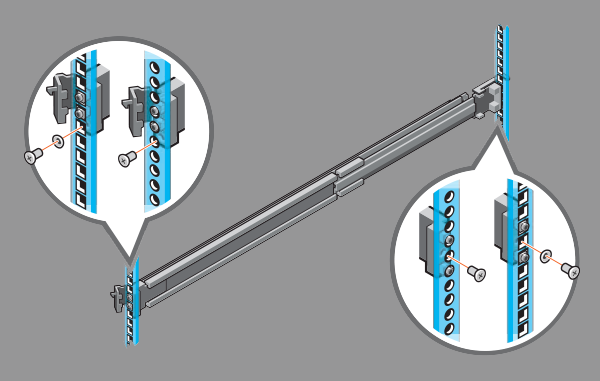
- Installing and Removing Tooled Rails (Threaded Hole Racks).
- Remove the pins from the front and rear mounting brackets using a flat-tipped screwdriver (1).
- Pull and rotate the rail latch sub-assemblies to remove them from the mounting brackets (2).
- Attach the left and right mounting rails to the front vertical rack flanges using two pairs of screws (3).
- Slide the left and right back brackets forward against the rear vertical rack flanges and attach them using two pairs of screws (4).
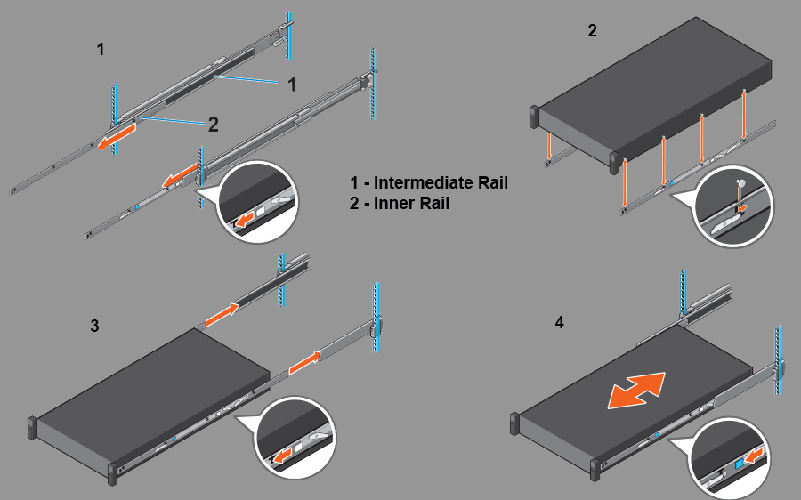
- Installing the System in a Rack.
- Pull the inner slide rails out of the rack until they lock into place (1).
- Locate the rear rail standoff on each side of the system and lower them into the rear J-slots on the slide assemblies (2).
- Rotate the system downward until all the rail standoffs are seated in the J-slots (3).
- Push the system inward until the lock levers click into place. Press the slide-release lock buttons on both rails and slide the system into the rack (4).
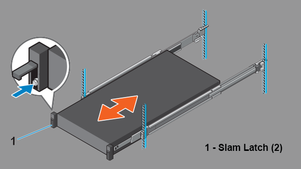
- Engaging and Releasing the Slam Latch.
Note: For systems not equipped with slam latches, secure the system using screws, as described in Step C of this procedure.
- Facing the front, locate the slam latch on either side of the system (1).
- The latches engage automatically as the system is pushed into the rack and are released by pulling up on the latches (2).
- To secure the system for shipment in the rack or for other unstable environments, locate the hard-mount screw under each latch and tighten each screw with a #2 Phillips screwdriver (3).
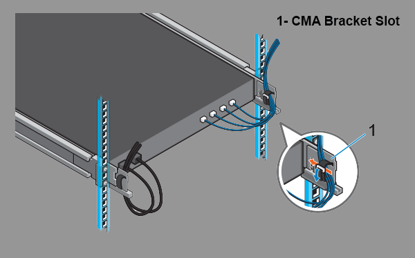
- Routing the Cables.
- Locate the outer brackets on the interior sides of both rack flanges (1).
- Bundle the cables gently, pulling them clear of the system connectors to the left and right sides (2).
- Thread the hook and loop straps through the tooled slots on the outer brackets on each side of the system to secure the cable bundles (3).