Access Point Overview
C-250 or C-260 is a tri-radio 802.11ax access point.
This chapter provides an overview of the C-250 or C-260 access point (AP) and describes:
Front Panel
The front panel of the C-250 or C-260 has 6 LEDs that indicate the status of various device functions.
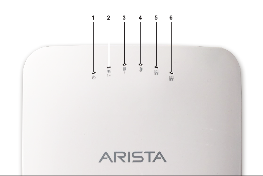
| Label | Description |
|---|---|
| 1 | Power |
| 2 | 2.4 GHz Radio |
| 3 | 5 GHz Radio |
| 4 | Third Radio |
| 5 | LAN1 |
| 6 | LAN2 |
Power LED: The following table describes the Power LED states.
| Green | Orange | |
|---|---|---|
| Solid | Running at full capability | Running at reduced capability |
| Blinking | Received IP address, but not connected to the server | Did not receive an IP address |
Reduced capability indicates that the AP is getting lower than the required maximum power from the PoE switch, i.e., 802.3at instead of 802.3bt.
LAN1 LED: ON when the corresponding interface is up.
LAN2 LED: ON when the corresponding interface is up and either wired guest or link aggregation is configured.
Radio LEDs: ON when the corresponding radio is operational.
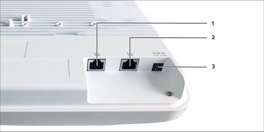
Rear Panel
The rear panel of the AP has its DC power port and 802.3bt compliant PoE LAN ports to power the device and connect it to a wired LAN.
| Label | Description |
|---|---|
| 1 | LAN1 |
| 2 | LAN2 |
| 3 | Power |
The first of the following tables shows port details for C-250, and the second one shows port details for C-260.
| Port | Description | Connector Type | Speed/Protocol |
|---|---|---|---|
| Power | 12V DC | 5.5 mm overall diameter / 2.1 mm center pinhole | N/A |
| LAN 1 | 2.5 Gigabit Ethernet with 802.3bt compliant PoE | RJ-45 | 100/1000 Mbps / 2.5 Gbps Ethernet |
| LAN 2 | 2.5 Gigabit Ethernet with 802.3bt compliant PoE | RJ-45 | 100/1000 Mbps / 2.5 Gbps Ethernet |
| Port | Description | Connector Type | Speed/Protocol |
|---|---|---|---|
| Power | 12V DC | 5.5 mm overall diameter / 2.1 mm center pinhole | N/A |
| LAN 1 | 5 Gigabit Ethernet with 802.3bt compliant PoE | RJ-45 | 100/1000 Mbps / 2.5 /5 Gbps Ethernet |
| LAN 2 | 5 Gigabit Ethernet with 802.3bt compliant PoE | RJ-45 | 100/1000 Mbps / 2.5/5Gbps Ethernet |
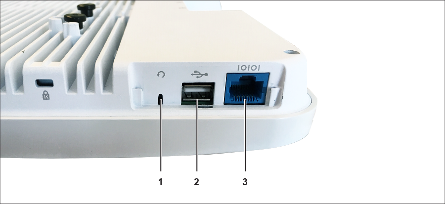
Side Panel
The side panel of the AP has a console port, a USB port, and a Reset pin.
| Label | Description |
|---|---|
| 1 | Reset |
| 2 | USB |
| 3 | Console |
| Port | Description | Connector Type | Speed/Protocol |
|---|---|---|---|
| Console |
Establish ‘config shell’ terminal session via serial connection |
RJ-45 |
|
| USB | USB 2.0 port | USB | Future Use |
| Reset |
Reset to factory default settings port. Hold down and power cycle the device to reset. |
Pinhole push button | N/A |
When you reset the AP, the following settings are reset:
- Config shell password is reset to config.
- Server discovery value is erased and changed to the default, redirector.online.spectraguard.net (primary) and wifi-security-server (secondary).
- All the VLAN configurations are lost.
- If a static IP is configured on the AP, the IP address is erased and DHCP mode is set. The factory default IP address of the AP is 169.254.11.74.