Side Panel of O-105E
The side panel of the O-105E has LEDs that indicate the working of the device.
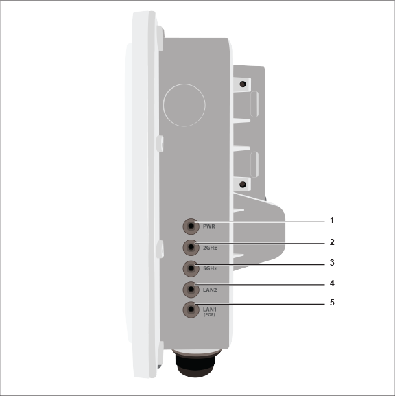
| Label | Description |
|---|---|
| 1 | Power |
| 2 | 2.4 GHz Radio |
| 3 | 5 GHz Radio |
| 4 | LAN2 |
| 5 | LAN1 (PoE) |
Power LED: The following table describes the Power LED states.
| Green | Orange | |
| Solid | Running at full capability | Running at reduced capability |
| Blinking | Received IP address, but not connected to the server | Did not receive an IP address |
Reduced capability indicates that the AP is getting lower than the required maximum power from the PoE switch, i.e., 802.3af instead of 802.3at.
LAN1 LED: ON when the corresponding interface is up.
LAN2 LED: ON when the corresponding interface is up and either wired guest or link aggregation is configured.
Radio LEDs: ON when the corresponding radio is operational.