White Paper
VXLAN Overview
Table of Contents
– Virtual Extensible LAN (VXLAN)
– VXLAN Use Cases
– Implementation
– IP Header
– UPD Header
– VXLAN Header
– Packet Walk-Through
– Implementation Considerations
– Payloads & Bandwidth Utilization
– Multicast Requirements
– ARP Cache and Mac Table
– Considerations
– Summary
This document provides an overview of how VXLAN works. It also provides criteria to help determine when and where VXLAN can be used to implement a virtualized Infrastructure. Arista, Broadcom, Intel, VMware and others developed the VXLAN specification to improve scaling in the virtualized Datacenter. VXLAN is a powerful tool for extending layer 2 subnets across layer 3 network boundaries. It solves VM portability limitations by encapsulating traffic and extending it across L3 gateways, allowing VMs to be hosted by servers residing on foreign IP subnets.
Virtual Extensible LAN (VXLAN)
A key benefit of virtualization, especially in the case of VMware’s vSphere, is the ability to move virtual machines (VMs) among data center servers while the VM is running! This feature, called stateful or live vMotion, simplifies server administration and provisioning without impacting VM functionality or availability. To support vMotion, VMs must always remain in their native IP subnet. This guarantees network connectivity from the VM to users on the rest of the network.Unfortunately, IP sub-netting limits the VM mobility domain to the cluster of vSphere servers whose vSwitches are on identical subnets. As an example, if a systems administrator wants to move a VM to an underutilized server, he has to make sure that vMotion won’t break the VM’s network connections. This normally isn’t a problem for small clusters of subnets, but as the number of subnets, VMs and servers grow, administrators will run into IP subnet roadblocks that limit vMotion.
VXLAN Use Cases
For existing deployments, there is no change to the Arista 7500 Series chassis. Designed with future proofing in mind, the existing Arista DCS-7504 and DCS-7508 chassis are capable of supporting the higher performance 7500R line cards and fabric modules. The original Arista 7500 Series that started out with 480 Gbps forwarding throughput (48 x 10G) now supports up to 3.6 Tbps (36 x 100G) per line card slot.VXLAN’s layer 2 tunneling feature overcomes IP subnetting limitations, allowing administrators to move VMS to any server in the data center, regardless of the data center’s sub-netting scheme. This allows administrators to implement a reliable L3 architecture in the data center while also supporting VM mobility across all the servers in the data center. Application Examples:
- Hosting provider provisioning a cloud for its customer
- VM Farm that has outgrown its IP address space but wants to preserve the data center network architecture
- Cloud service provider who’s multi-tenant offering needs to scale beyond 802.1q VLANS
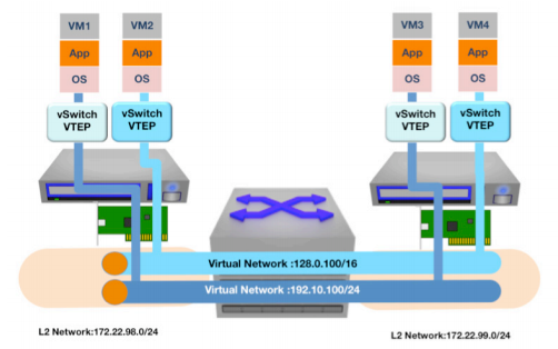
Figure 1:
Using Virtual Tunnel End Points (VTEPs) to Transport Multiple Virtual Networks
VXLAN Implementation
The network infrastructure must support the following to support VXLANS:
- Multicast support: IGMP and PIM
- Layer 3 routing protocol: OSPF, BGP, IS-IS
Each VXLAN network segment is associated with a unique 24bit VXLAN Network Identifier, or VNI. The 24-bit address space allows scaling virtual networks beyond the 4096 available with 802.1Q to 16.7 million possible virtual networks. However, multicast and network hardware limitations will reduce the useable number of virtual networks in most deployments. VMs in a logical L2 domain use the same subnet and are mapped to a common VNI. It’s the L2 to VNI mapping that lets VMs communicate with one another. Note that VXLAN doesn’t change layer 3 addressing schemes. IP addressing rules employed in a physical L2 still apply to the virtual networks.
VXLANs maintain VM identity uniqueness by combining the VM’s MAC address and its VNI. This is interesting because it allows for duplicate MAC addresses to exist in a datacenter domain. The only restriction is that duplicate MACs cannot exist on the same VNI.
Virtual machines on a VNI subnet don’t require any special configuration to support VXLAN because the encap/decap and VNI mapping are managed by the VTEP built into the hypervisor. VXLAN capable switching platforms are similarly responsible for the encap/decap overhead of 802.1q attached network devices. The VTEP must be configured with the layer-2 or IP subnet to VNI network mappings as well as VNI to IP multicast groups. The former mapping allows VTEPS to build forwarding tables for VNI/MAC traffic flows and the latter allows VTEPs to emulate broadcast/multicast functions across the overlay network. Synchronization of VTEP configurations can be automated with common configuration management tools like RANCID, or they can be managed through VMware’s vCenter Orchestrator, Open vSwitch or other systems.
VXLAN Frame Encapsulation and Forwarding
With these elements in place, the VTEP executes its forwarding rules:1. If the source and destination MAC addresses live on the same host, traffic is locally switched through the vSwitch and no VXLAN encap/decap is performed.
2. If the destination MAC address live is not on the ESX host, frames are encapsulated in the appropriate VXLAN header by the source VTEP and are forwarded to the destination VTEP based on its local table. The destination VTEP will unbundle the inner frame from the VXLAN header and deliver it on to the recipient VM.
3. For unknown unicast or broadcast/multicast traffic, the local VTEP encapsulates the frame in a VXLAN header and multicasts the encapsulated frame to the VNI multicast address that is assigned to the VNI at the time of creation. This includes all ARPs, Boot-p/DHCP requests, etc. VTEPs on other hosts receive the multicast frame and process them much the same way unicast traffic is (see note 2 above).
The implementation of this tunneling scheme is relatively simple compared to other schemes, such as MPLS or OTV, because the administrator only needs to configure VNI or IP mappings and multicast addresses. The rest is managed by the VTEPs.
Here are additional details of the frame format:
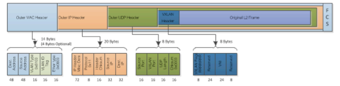
Figure 2:
VXLAN Header Format
Destination Address
– This is set to the MAC address of the destination VTEP if it’s on the same subnet. If the VTEP is on a different subnet the address is set to the next hop device, usually a router.VLAN
– This is optional for a VXLAN implementation. It will default to the 802.1Q Tagged Protocol Identifier (TPUD) Ethertype 0X8100 and has an associated VLAN ID tag.Ethertype
– This is set to 0X0800 to denote an IPv4 payload packet. There’s currently no IPV6 support yet but it’s under investigation future deployment.IP Header
Protocol
– This is set to 0 × 11 to indicate it’s a UDP packet. Source IP: This is set to the VTEP source IP addressDestination IP
– This is set to the destination VTEP IP address. If unknown/unlearned or is a broad/multi-cast address, then VXLAN simulates a network broadcast using its multicast group. Here’s a brief outline:- Destination IP is replaced by the IP multicast group that corresponds to the VNI of the source virtual machine.
- Frame is multicast and all VTEPs on the VNI multicast group receive the frame. They in turn unbundle the frame, learn the source ID and VNI mapping for future use and then forward or drop the packet based on the frame type and local forwarding table information.
- The VTEP hosting the target virtual machine will encapsulate and forward the virtual machines reply to the sourcing VTEP.
- The source VTEP receives the response and also caches the ID and VNI mapping for future use.
UPD Header
Source Port
– Set by transmitting VTEP. This value can be hashed from the bundled Ethernet headers so that port channel or ECMP hashing algorithms can leverage this value for traffic balancing.Destination Port
– VXLAN IANA port. Vendor specific.UDP Checksum
– Should be set by VTEP source to 0 × 0000. If the receiving VTEP receives a checksum that isn’t 0 × 0000, the frame should be checked and discarded if checksum fails.VXLAN Header
VXLAN Flags
– Aside from bit 3, the VNI bit, all reserved bits set to zero. The VNI bit is set to 1 for a valid VNI.VNI
– This 24-bit field is the VXLAN network ID.Reserved
– Reserved fields of 24 and 8 bits that are set to zero.VXLAN Packet Walk-Through
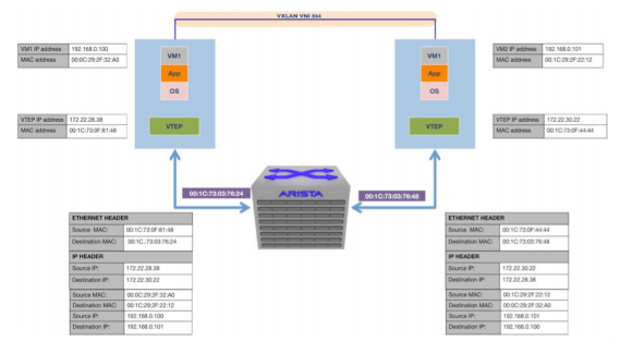
Figure 3:
VM to VM Communication Using VXLAN
Here’s a packet walkthrough of a session initiated between VMs 1 and 2 residing on different hosts in different IP subnets. We assume bring up state: no associations have been learned yet.
1. VM1 sends an ARP packet requesting the MAC address associated with 192.168.0.101.
2. The ARP is encapsulated in a Multicast packet by VTEP1 and is multicast to the group associated to VNI 864
3. All VTEPs associated with VNI 864 receive the packet and add the VTEP1/VM1 MAC mapping to their tables
4. VTEP2 receives the multicast packet, unbundles the frame and floods it to the port groups in VNI 864
5. VM2 receives the ARP and responds to VM1 with its MAC address
6. VTEP2 encapsulates the response as a unicast IP packet and forwards it to VTEP1. The response is unicast since VTEP 2 has learned the VTEP1/VM1 MAC mapping from the original simulated ARP
7. VTEP1 receives, unbundles and forwards the response packet to VM1. At this point, communications between VM1 and 2 are established and associations are programmed into all relevant state machines
For any further unicast traffic being sourced from 192.168.0.100 destined to 192.160.0.101, VTEP 1 will take the packet and prepend the following headers:
- VNI VXLAN header = 864
- Standard UDP header with the UDP checksum set to 0 × 0000 and the VXLAN destination port set to the correct IANA port based on vendor.
- Destination IP set to the IP address of VTEP 2 and the protocol ID set to UDP, or 0x011
- Standard MAC header with the next hop MAC address. (In the above example, the next hop is the router interface with MAC address 00:13:73: 0C: 76: 24.)
Implementation Considerations
A key benefit of virtualization, especially in the case of VMware’s vSphere, is the ability to move virtual machines (VMs) among data center servers while the VM is running! This feature, called stateful or live vMotion, simplifies server administration and provisioning without impacting VM functionality or availability. To support vMotion, VMs must always remain in their native IP subnet. This guarantees network connectivity from the VM to users on the rest of the network.Network Datagram Payloads and Bandwidth Utilization
The VXLAN encapsulation header adds 50 bytes to the overall size of an Ethernet frame. Therefore it is imperative the infrastructure support jumbo frames. One should also consider the increased bandwidth used to support VXLAN traffic. Juxtaposing multiple networks with an increased packet size will consume more bandwidth so its prudent to implement this scheme over 10Gb or higher capacity network technologies.Using standard IP datagrams helps VXLAN offer options for implementing long distance vMotion or High Availability (HA). VXLAN frames even take information from the embedded packet to add variability in its packet header to aid load-sharing algorithms. However, if the network designer is interested in leveraging VXLANs in disaster recovery or remote mirrored data center applications, its important to ensure that VMware vMotion/HA heartbeat round trip delay not exceed 10 milliseconds. Designers can leverage high bandwidth, low latency switching with traffic prioritization services to fulfill these requirements and extend the virtualized data center.
Multicast Requirements
As previously mentioned, IP multicast services are used to simulate broadcast, unknown unicast and multicasts within the VXLAN network. This is required for VXLANs. While not required, the current recommended configuration is to map one multicast group to each VNI. This ensures MAC table updates are only sent to VTEPs that require them. It is possible to use only one multicast address for every VNI, but this will effectively flood addresses to VTEPs not needing them and create unnecessary traffic flows in the network.PIM sparse, dense mode and BIDIR all provide multicast capabilities to support VXLANs. While some administrators have concerns with PIM, especially those who experienced network outages due to CPU bound PIM processing, its important to note that modern switching platforms support PIM in hardware and can support large scale PIM deployments without adversely impacting the performance or reliability of the network.
ARP Cache and Mac Table Considerations
VMs in a VXLAN Network communicate to non-virtual networks through a VTEP. VTEPs can either be a software appliance, like a virtual firewall or VMware vShield, or in a VXLAN capable switch. In either case, if the VTEP provides routing services, the ARP cache must accommodate the number of VMs on the virtual networks it services to avoid unnecessary ARPS.VM traffic encapsulated in VXLAN frames use the MAC IDs of the server’s VTEP. This reduces the number of MAC address entries in the data center’s physical switches. Ideally, a physical VXLAN network would only be required to learn the MAC addresses for the VTEPs and management interfaces of the hosts within the data center. However, while this may work in smaller scale VM deployments, it is prudent to partition VMs and server clusters in subnets to accommodate the traffic volumes sustainable with up to dozens of VMs per server.
Summary
| Table 1: Summary table of capabilities | ||
|---|---|---|
| Feature and Scaling Capability | 802.1Q VLAN | VXLAN |
| Number of virtual networks | 4K: limited by spanning tree scaling | 16+ million: limited by the number of multicast groups supported by your network’s multicast routers |
| Network diameter | As far as 802.1Q VLANS are permitted | As far as PIM multicast groups are permitted |
| Network packet size | 1.5K or 9K | Add 50 bytes for VXLAN header |
| Multicast requirements | None | PIM, SM, DM, or Bi-dir. Number of groups defines number of virtual networks |
| Routing support | Any 802.1Q capable router or switch | Any router or switch working with VMware vShield, vEdge and any VTEP capable router |
| ARP Cache | Limits the VMs supported per VLAN | Cache on VMware or VTEP limits VMs supported per VNI |
| Mac table | VM MAC addresses count against switch MAC table limits | VTEP MAC addresses count against switch MAC table limits |
VXLAN is a powerful tool for extending layer 2 subnets across layer 3 network boundaries. It solves VM portability/vMotion limitations by encapsulating traffic and extending it across L3 gateways, allowing VMs to be hosted by servers residing on foreign IP subnets. VXLANs can also overlay multiple subnets across a data center infrastructure. The number of virtual networks is limited only by the raw bandwidth of the underlying network and the multicast subnets available to simulate broadcast/multicast traffic of the VXLAN network. Given the right hardware, VXLANS can eclipse the 4K VLAN limit of 802.1Q without compromising the stability of the network. VXLANs use established IP transport along with routing for encapsulated traffic. Therefore, link aggregation, loop detection and breaking, and path discovery are resolved through tried and proven OSPF, BGP or IS-IS protocols. VXLANs can work on existing infrastructures without the need to retrofit them. Support from VMware, Intel, Broadcom, Arista, Open vSwitch and others guarantees interoperability and avoids vendor lock in. With VXLANs, systems and network administrators can scale cloud virtualization to new levels and serve more users cost effectively.
Copyright © 2016 Arista Networks, Inc. All rights reserved. CloudVision, and EOS are registered trademarks and Arista Networks is a trademark of Arista Networks, Inc. All other company names are trademarks of their respective holders. Information in this document is subject to change without notice. Certain features may not yet be available. Arista Networks, Inc. assumes no responsibility for any errors that may appear in this document. Jan 2016 02-0035-01