
Segment Routing Over IPv6 (SRv6)
Segment Routing over IPv6 (SRv6) provides a pure IPv6 transport and service data plane, replacing MPLS label stacks with standard IPv6 headers and Micro-SIDs (uSIDs). SRv6 allows EOS switches to implement network programming directly inside standard IPv6 headers.
Micro segments, SRv6 uSID or uSID, provides an extension of SRv6 architecture, specifically designed to represent SRv6 SIDs in an extremely compact way. It addresses the overhead of using full 128-bit IPv6 SIDs for routing. Instead of using a 128-bit address for single SID, EOS packs multiple uSIDs into a single 128-bit address. Each 128-bit address composes a block value representing the domain followed by multiple uSIDs, each of the same bit length. EOS fills leftover bits filled with trailing zeros. This allows for a complete SRv6 path to be represented by a 128-bit IPv6 address. Like a regular SID, each uSID associated with a specific behavior on the SRv6 capable node. SRv6 uN refers to the End behavior with uSIDs.
- DCS-7060X6
- DCS-7280R3
- DCS-7500R3
- DCS-7800R3
- DCS-7800R4-*
- DCS-7800R4K-36PE-LC
- DCS-7800R4M-36PE-LC
- DCS-DL-7700R4K-*
- DCS-7280R4-32*
- DCS-7280R4K-32*
- DCS-7282R4*
| Term | Definition |
|---|---|
| uSID Block Prefix | The IPv6 prefix that allocates all of uSIDs. Referred to as uSID Domain. |
| uSID Block Length | The 32-bit prefix length of the uSID Block prefix |
| uSID Length | The 16-bit size of the uSID value |
| uSID Format | A concise representation of the uSID block length and the uSID
length in the format, FXXYY, where
XX denotes the uSID block length and
YY denotes the uSID length. For example,
F3216 indicates a uSDI block length of 32-bits
and a uSID length of 16-bits. |
| uSID Container | A 128-bit IPv6 SRv6 SID with the structure
<uSID_block_prefix><uSID1><uSID2>...<uSIDn>.
For example, F3216, the uSID container has a 32-bit lock prefix
followed by a maximum of 6 uSIDs, each with a 16-bit length. |
| Segment Routing Header (SRH) | SRv6 uses an IPv6 routing extension header called a Segment Routing Header. |
| System SFIB Table | Every locally configured uN has a corresponding entry in the Segment Forwarding Information Database (SFIB). EOS performs a Longest Prefix Match (LPM) lookup in this table to determine if the IPv6 IPv6 Destination Address (DA) matches a locally instantiated uN, and after matching, performs SRv6 processing on the packet. |
| Longest Prefix Match (LPM) | Enables transit core routers to forward SRv6 traffic using standard IPv6 routing hardware without previous knowledge of VPN services or individual function instructions. |
SRv6 Operation Overview
The network diagram uses a 3-tier network topology to explain the SRv6 operations. The IPv6 prefix for each switch represents the uN of the node, and uses static routes for reachability to the uN. Each node has static routes to the uNs of the neighboring nodes.
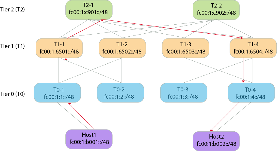
ipv6 route fc00:1:6501::/48 2001:db8:10::1101The next-hop address corresponds to the interface address on T1-1 for the link between T0-1 and T1-1.
ipv6 route fc00:1:6501::/48 Ethernet 1/1 fe80::9e69:edff:fe62:4153Similarly, T1-1 has static routes to the uN of T1-2 and all other nodes have static routes to provide reachability to the neighboring nodes uNs.
SRv6 Forwarding
The switch, Host1, requires prior knowledge of uNs of all nodes in the
path to send traffic to Host2. With that information, Host1 computes
the IPv6 address that represents the desired path. In the network topology example,
SRv6 computes the address as fc00:1:1:6501:c901:6504:4:b002 using
the initial address of fc00:1::/32 as the uSID block and then the
16-bit vSID values of each node in the path. This represents a path consisting of 6
nodes in a single 128-bit IPv6 address.
- Calculates the IPv6 DA as
fc00:1:1:6501:c901:6504:4:b002. - Designates the active SID as
fc00:1:1::/48. - T0-1 recognizes the active SID has the same value as its uN.
- As per uN processing, T0-1 shifts the uSID value left and moves the rest of the DA bits to the left and fills trailing 16-bits with 0's.
- After shifting the values, the DA has a value of
fc00:1:6501:c901:6504:4:b002::. - T0-1 performs a lookup of the resulting DA in the IPv6 FIB.
- Since a static route exists for fc00:1:6501::/48, the uN of the neighboring node, T1-1, the lookup matches the route and sends the packet to T1-1.
- T1-1 recognizes the active SID, fx00:1:6501::/48, as its uN and performs the
same shift and look operation in Step 4. It then sends the packet to
T2-1.
The IPv6 DA keeps changing as the packet traverses the SRv6 path.
- When the packet reaches T0-4, the IPv6 DA has a value of
fc00:1:4:b002::. - T0-4 recognizes the active SID as its uN, perform the shift operation, and
create the IPv6 DA as
fc00:1:b002::/48. It then performs an Longest Prefix Match (LPM) lookup for the address. - Because the network has a static route for fc00:1:b002::/48 to Host2, it sends the packet to Host2.
- Host2 recognizes the active SID as its uN and does not find any further uSIDs in the uSID container. Host2 then consumes the packet.
Configuring SRv6
feature srv usid f3216- DCS-7280R3
- DCS-7280R4-32*
- DCS-7280R4K-32*
- DCS-7282R4*
- DCS-7500R3
- DCS-DL-7700R4K-*
- DCS-7800R3
- DCS-7800R4-*
- DCS-7800R4K-36PE-LC
- DCS-7800R4M-36PE-LC
Review the example TCAM profile here.
Configuring an SRv6 Locator
An SRv6 uN locator provides a routable IPv6 prefix that identifies a specific SRv6-capable in the network. It consists of a uSID domain and a uSID value.
Before configuring a locator, first configure the micro-segment domain referenced by the locator using the following commands:
- Enter SRv6 configuration mode on the switch:
switch(config)# router srv6 switch(config-router-srv6)# - Enter the default VRF configuration submode:
switch(config-router-srv6)# vrf default switch(config-router-srv6-vrf-default)# - Enter the Micro-Segmentation Domain Configuration mode, and enter a domain with
a unique name:
switch(config-router-srv6-vrf-default)# micro-segment domain srv6_1 - Configure the uSID block prefix,
fc00:0::/32, for the Micro-Segmentation domain:
This step specifies the exact IPv6 prefix that uniquely identifies this micro-segment domain across the network. When an SRv6 router receives a packet matching the configured block prefix, the router recognizes the packet as a uSID container, and performs the left-shift address operations to advance to the next micro-SID in the chain.switch(config-router-srv6-vrf-default-domain)# block fc00:0::/32 - Exit the Micro-Segmentation Domain Configuration Mode:
switch(config-router-srv6-vrf-default-domain)# exit switch(config-router-srv6-vrf-default)# - Configure the locator with a unique name, locator1:
switch(config-router-srv6-vrf-default)# locator locator1 switch(config-router-srv6-vrf-default-locator)# - Add the locator micro-segment domain and uSID value:
Configure the usid_value in either decimal or hexadecimal format. This configuration usesswitch(config-router-srv6-vrf-default-locator)# prefix micro-segment domain srv6_1 end usid 5145751547(0xC901). - Exit the Locator Configuration Mode and then enter the Micro-Segmentation Domain
Configuration mode. Add the Global ID Block range to each micro-segment
domain:
By default, the configuration uses the range 1 - 57343 (0xDFFF).switch(config-router-srv6-vrf-default-locator)# exit switch(config-router-srv6-vrf-default)# micro-segment domain srv6_1 switch(config-router-srv6-vrf-default-domain)# gib range 1 - 57330 switch(config-router-srv6-vrf-default-domain)#
Disabling SRv6 Functionality
Use the following commands to disable SRv6 on a switch:
- Enter SRv6 Configuration Mode:
switch(config)# router srv6 - Enter VRF Configuration Mode:
switch(config-router-srv6)# vrf default - Disable SRv6:
switch(config-router-srv6-vrf-default)# disabled
SRv6 Ping
To assist with troubleshooting and debugging networks, perform reachability checks on target uNs, node SIDs, through specific paths. Use the SRv6 ping utility with the ping srv6 command and ping a target uN through a specific path consisting of a list of uNs of each node in the path.
The command has the following format and options:
switch# ping srv6 sid targetsid via segment-list sid1 sid2 sid3 ... ping-options ?- dont-frag - Disable fragmentation.
- interval - Specify the time to wait between sending each packet.
- repeat - Specify the repeat count.
- size - Specify the datagram size.
- source - Specify the source address or choose an address from specified interface.
- timeout - Specify the time to wait for a response.
Example Output
switch# ping srv6 sid fc00:42:3:: via segment-list fc00:42:4:: fc00:42:7:: fc00:42:6::
Pinging fc00:42:4:7:6:3:: [fc00:42:4:7:6:3::] with 64 bytes
64 bytes from fc00:42:3:: icmp_seq=1  ttl=61 time=6.475ms
64 bytes from fc00:42:3:: icmp_seq=2  ttl=61 time=6.153ms
64 bytes from fc00:42:3:: icmp_seq=3  ttl=61 time=6.429ms
64 bytes from fc00:42:3:: icmp_seq=4  ttl=61 time=6.190ms
64 bytes from fc00:42:3:: icmp_seq=5  ttl=61 time=5.827ms

--- fc00:42:4:7:6:3:: ping statistics ---
5 packets transmitted, 5 received, 0% packet loss, time 4009.661ms
rtt min/avg/max/mdev = 5.827/6.215/6.475/0.259ms
A uN prefix must be configured on an interface on the target node in order for the ping srv6
to return information. From the example, fc00:42:3::/48 must be configured on a
loopback interface on the target node.
- The source specified in the command line.
- The local address configured for SRv6.
- The IPv6 address configured on an interface.
SRv6 derives the destination address by concatenating the common address block of the segment list and target, with the sequential uSIDs from the segment list and the final target uSID.
SRv6 Traceroute
The traceroute srv6 command identifies the path used by SRv6 traffic and determines the intermediate hops to a target uN along a specific path consisting of a list of uSIDs for each node in the path. The command can assist with understanding how the destination address within the SRv6 header changes as the packets traverse the SRv6 network.
The command has the following format and option:
switch# ping srv6 sid targetsid via segment-list sid1 sid2 sid3 ... traceroute-options- source - Specify the source address or select an address from the specified interface.
Similar to SRv6 Ping, configure the uN prefix with a /48 address representing the combined block and function lengths on a loopback interface. Also SRv6 Traceroute uses a mechanism similar to SRv6 Ping to determine the source address in the traceroute probe packets.
Example Output
switch# traceroute srv6 sid fc00:42:3:: via segment-list fc00:42:2:: traceroute to fc00:42:2:3::, 30 hops max, 64 byte packets
1 2001:db8:200:12::2 2.085ms 1.272ms 1.090ms
  DA: fc00:42:2:3::
2 2001:db8:200:23::3 2.014ms 1.407ms 1.405ms
  DA: fc00:42:2:3::
3 fc00:42:3:: 2.154ms 1.845ms 1.790ms
  DA: fc00:42:3::
The output displays information about the hop number, the source address of the ICMPv6 responses, and the destination address of the probe packets as received at an intermediate router.
In the sample output, when attempting to reach target SID fc00:42:3::
through the SID fc00:42:2::, the probe packets use the destination
address fc00:42:2:3::.The first hop replied with an ICMPv6 response,
containing 2001:db8:200:12::2 as the source address in the IPv6 header.
The destination address in the received probe packets at the first hop uses
fc00:42:2:3::. Similarly the second hop replies. Notice that the
destination address in the probe packets alters when reaching the second hop. This may
be due to the change in the destination address of probes at the first hop.
Displaying SRv6 Configurations
This topic contains the following sections:
- Displaying SRv6 Locator Information
- Displaying a Specific SRv6 Locator Information
- Displaying SRv6 Domains Information
- Displaying Specific SRv6 Domain Information
- Displaying SRv6 Route Information
- Displaying Specific SRv6 Route Information
- Displaying SRv6 Capabilities
Displaying SRv6 Locator Information
switch# show srv6 locator
SRv6 configuration for VRF default
Administrative status: enabled
Operational status: enabled
Encapsulation source address: 2001:db8:100::1
Number of configured locators: 2

Locator LOC1
State: active
Type: micro-SID
Micro-SID domain: DOM1
uSID: 1 (0x1)
Prefix: fc00:42:1::/48
Block length: 32
Function length: 16

Locator LOC2
State: active
Type: micro-SID
Micro-SID domain: DOM1
uSID: 2 (0x2)
Prefix: fc00:42:2::/48
Block length: 32
Function length: 16
Displaying a Specific SRv6 Locator Information
switch# show srv6 locator LOC2
SRv6 configuration for VRF default
Administrative status: enabled
Operational status: enabled
Encapsulation source address: 2001:db8:100::1
Number of configured locators: 2

Locator LOC2
State: active
Type: micro-SID
Micro-SID domain: DOM1
uSID: 1 (0x1)
Prefix: fc00:42:1::/48
Block length: 32
Function length: 16
Displaying SRv6 Domains Information
Each Arista switch can have multiple SRv6 domains configured on it. Use the following command to display the configured domains:
switch# show srv6 domain
SRv6 configuration for VRF default
Number of configured domains: 2

Domain DOM1
State: active
Block: fc00:41::/32
GIB Range: 1 - 57343
uSID Length: 16

Domain DOM2
State: active
Block: fc00:42::/32
GIB Range: 1 - 57343
uSID Length: 16
Displaying Specific SRv6 Domain Information
To display information about a specific SRv6 domain, add the domain name to the command:
switch# show srv6 domain DOM1
SRv6 configuration for VRF default
Number of configured domains: 2

Domain DOM1
State: active
Block: fc00:41::/32
GIB Range: 1 - 57343
uSID Length: 16
Displaying SRv6 Route Information
Configuring a locator adds an entry to the system SFIB table. Use the following command to display SRV6 routes:
switch# show srv6 route
VRF default
Source Codes: S - Static
End Behaviors: End - Endpoint

S  fc00:42:1::/48, End with NEXT-CSID, locator LOC1
    via IPv6 lookup, VRF default
S  fc00:42:2::/48, End with NEXT-CSID, locator LOC2
    via IPv6 lookup, VRF default
Displaying Specific SRv6 Route Information
Configuring a locator adds an entry to the system SFIB table. Use the following command to display SRV6 routes added by a specific locator:
switch# show srv6 route locator Locator1
VRF default
Source Codes: S - Static
End Behaviors: End - Endpoint

S  fc00:42:1::/48, End with NEXT-CSID, locator <LOCATOR_NAME>
    via IPv6 lookup, VRF default
Displaying SRv6 Capabilities
Use the following command to display SRv6 capabilities on a switch:
switch# show srv6 capabilities
Supported end behaviors
End: supported
End.X: unsupported
End.DX4: unsupported
End.DX6: unsupported
End.DT4: supported
End.DT6: supported

Supported end behavior flavors
PSP: supported
USP: unsupported
USD: supported
Next-CSID: supported

Supported headend behaviors
H.Encaps: supported
H.Encaps.Red: unsupported
H.Insert: unsupported
H.Insert.Red: unsupported

Other Capabilities
uSID Formats: F3216
SRv6 Commands
Global Configuration
router srv6
The router srv6 command in Global Configuration Mode places the switch into Segment Routing Configuration Mode and allows the configuration of SRv6 features on a switch. Once in Segment Routing Configuration Mode, using the vrf default places the switch into Segment Routing VRF Configuration Mode. Once in Segment Routing VRF Configuration Mode, disable the configuration or add a local IPv6 address.
Command Mode
Global Configuration
Default VRF Configuration Mode.
Command Syntax
router srv6
vrf default
[disabled] [local address ip6_address]
Parameters
- router srv6 - Enters Segment Routing Configuration Mode.
- vrf default - Enters the Default VRF Configuration Mode.
- disabled - Disables the SRv6 functionality on the switch.
- local address ip6_address - Define the source IPv6 address used in the outer IPv6 encapsulation header for traffic originating from the default VRF.
Examples
Use the following commands to enter Segment Routing and VRF Configuration Modes:
switch(config)# router srv6
switch(config-router-srv6)# vrf default
switch(config-router-srv6-vrf-default)#
Use the following command to disable the SRv6 configuration on the switch:
switch(config-router-srv6-vrf-default)# disabled
switch(config-router-srv6-vrf-default)#
Use the following command to add the local IPv6 address,
2001:db8:100::1, to the switch:
switch(config-router-srv6-vrf-default)# local address 2001:db8:100::1
switch(config-router-srv6-vrf-default)#
locator
The locator command in the Segment Routing VRF Configuration Mode defines a dedicated IPv6 prefix block allocated to a switch. The switch uses this block to derive local Segment Identifiers (SIDs) such as node SIDs (uN), adjacency SIDs (uA), and service SIDs. Once in Locator Configuration Mode, add the Interior Gateway Protocol (IGP) algorithm, and the prefix for the micro-segment domain name.
Command Mode
Segment Routing (SRv6) Configuration
VRF Default Configuration
Locator Configuration
Command Syntax
locator locator_name [igp algorithm flex-algo] algo_name ] [prefix micro-segment domain domain_name end usid usid
Parameters
- locator locator_name - Configure a name for the Locator.
- prefix micro-segment domain domain_name - Specify the micro-segment domain name previously configured on the switch.
- end usid usid - Specify a 16-bit end uSID to match the destination node.
- igp algorithm flex-algo algo_name - Specify the Flex-Algorithm name.
Example
Use the following commands to add the micro-segment domain, domain_1,
and an end uSID, 001, to the locator, Locate_3:
switch(config)# router srv6
switch(config-srv6)# vrf default
switch(config-router-srv6-vrf-default)# locator Locate_1
switch(config-router-srv6-vrf-default-locator)# prefix micro-segment domain domain_1 end usid 001
switch(config-router-srv6-vrf-default-locator)#
Use the following commands to add the IGP Flex-Algo, flex_red, to the configuration:
switch(config-router-srv6-vrf-default-locator)# igp algorithm flex-algo flex_red
switch(config-router-srv6-vrf-default-locator)#
micro-segment
The micro-segment command in the Segment Routing VRF Configuration Mode enables and controls Micro-Segment (uSID) behavior for the default VRF. Instead of using full, uncompressed 128-bit SRv6 service SIDs, this command instructs the switch to allocate and signal compressed uSIDs for tenant routing services associated with the VRF.
Command Mode
Segment Routing (SRv6) Configuration
VRF Default Configuration
Micro-Segment DomainConfiguration
Command Syntax
micro-segment domain domain_name block ip6_address/mask gib range hexadecimal usid length [16 | 32]
Parameters
- micro-segment domain domain_name - Configure a name for SRV6 Micro-Segment Domain.
- block ip6_address/mask - Specify a uSID prefix for the domain.
- gib range hexadecimal - Specify a range for the global uSID allocations. The parameter has a default range from ox000 to 0xDFF which provides 57,344 globally unique node IDs for a single domain.
- usid length [16 | 32] - Specify either 16-bit (standard) or 32-bit for extended or specialized functions.
Example
Use the following commands to create a micro-segment domain, MyDomain, with a usid length of 16-bits:
switch(config)# router srv6
switch(config-router-srv6)# vrf default
switch(config-router-srv6-vrf-default)# micro-segment domain myDomain
switch(config-router-srv6-vrf-default-domain)# usid length 16
switch(config-router-srv6-vrf-default-domain)#
show srv6 capabilities
The show srv6 capabilities command in the EXEC Mode displays the
capabilities of Arista switches on the network.
Command Mode
EXEC
Command Syntax
show srv6 capabilities
Parameters
- show srv6 domain - Display information about SRv6 capabilities on Arista switches.
Example
Use the following command to display SRv6 capabilities on a switch:
switch# show srv6 capabilities
Supported end behaviors
End: supported
End.X: unsupported
End.DX4: unsupported
End.DX6: unsupported
End.DT4: supported
End.DT6: supported

Supported end behavior flavors
PSP: supported
USP: unsupported
USD: supported
Next-CSID: supported

Supported headend behaviors
H.Encaps: supported
H.Encaps.Red: unsupported
H.Insert: unsupported
H.Insert.Red: unsupported

Other Capabilities
uSID Formats: F3216
show srv6 domain
The show srv6 domain command in the EXEC Mode displays the
status of SRv6 domains on the network.
Command Mode
EXEC
Command Syntax
show srv6 domain domain_name
Parameters
- show srv6 domain domain_name - Display information about all SRv6 domains or specify a specific domain.
Examples
Each Arista switch can have multiple SRv6 domains configured on it. Use the following command to display the configured domains:
switch# show srv6 domain
SRv6 configuration for VRF default
Number of configured domains: 2

Domain DOM1
State: active
Block: fc00:41::/32
GIB Range: 1 - 57343
uSID Length: 16

Domain DOM2
State: active
Block: fc00:42::/32
GIB Range: 1 - 57343
uSID Length: 16
To display information about a specific SRv6 domain, add the domain name to the command:
switch# show srv6 domain DOM1
SRv6 configuration for VRF default
Number of configured domains: 2

Domain DOM1
State: active
Block: fc00:41::/32
GIB Range: 1 - 57343
uSID Length: 16
show srv6 locator
The show srv6 locator command in the EXEC Mode displays the
status of SRv6 Locators on the network.
Command Mode
EXEC
Command Syntax
show srv6 locator locator_name
Parameters
- show srv6 locator locator_name - Display information about all SRv6 Locators or specify a specific locator.
Examples
Use the following command to display information about all SRv6 locators:
switch# show srv6 locator
SRv6 configuration for VRF default
Administrative status: enabled
Operational status: enabled
Encapsulation source address: 2001:db8:100::1
Number of configured locators: 2

Locator LOC1
State: active
Type: micro-SID
Micro-SID domain: DOM1
uSID: 1 (0x1)
Prefix: fc00:42:1::/48
Block length: 32
Function length: 16

Locator LOC2
State: active
Type: micro-SID
Micro-SID domain: DOM1
uSID: 2 (0x2)
Prefix: fc00:42:2::/48
Block length: 32
Function length: 16
LOC1:switch# show srv6 locator LOC2
SRv6 configuration for VRF default
Administrative status: enabled
Operational status: enabled
Encapsulation source address: 2001:db8:100::1
Number of configured locators: 2
Locator LOC2
State: active
Type: micro-SID
Micro-SID domain: DOM1
uSID: 1 (0x1)
Prefix: fc00:42:1::/48
Block length: 32
Function length: 16show srv6 routes
The show srv6 routes command in the EXEC Mode displays the
routes in the system SFIB table.
Command Mode
EXEC
Command Syntax
show srv6 routes
Parameters
- show srv6 routes - Display information about SRv6 entries in the system SFIB.
Example
Configuring a locator adds an entry to the system SFIB table. Use the following command to display SRV6 routes:
switch# show srv6 route
VRF default
Source Codes: S - Static
End Behaviors: End - Endpoint

S  fc00:42:1::/48, End with NEXT-CSID, locator LOC1
via IPv6 lookup, VRF default
S  fc00:42:2::/48, End with NEXT-CSID, locator LOC2
via IPv6 lookup, VRF default
Configuring a locator adds an entry to the system SFIB table. Use the following command to display SRV6 routes added by a specific locator:
switch# show srv6 route locator Locator1
VRF default
Source Codes: S - Static
End Behaviors: End - Endpoint

S  fc00:42:1::/48, End with NEXT-CSID, locator <LOCATOR_NAME>
via IPv6 lookup, VRF default